EP0892252A1 - Electrodes galvaniques des débimètres électromagnétiques - Google Patents
Electrodes galvaniques des débimètres électromagnétiques Download PDFInfo
- Publication number
- EP0892252A1 EP0892252A1 EP98118525A EP98118525A EP0892252A1 EP 0892252 A1 EP0892252 A1 EP 0892252A1 EP 98118525 A EP98118525 A EP 98118525A EP 98118525 A EP98118525 A EP 98118525A EP 0892252 A1 EP0892252 A1 EP 0892252A1
- Authority
- EP
- European Patent Office
- Prior art keywords
- liquid
- electrode
- bore
- face
- measuring tube
- Prior art date
- Legal status (The legal status is an assumption and is not a legal conclusion. Google has not performed a legal analysis and makes no representation as to the accuracy of the status listed.)
- Granted
Links
- 239000007788 liquid Substances 0.000 claims abstract description 30
- 239000000463 material Substances 0.000 claims abstract description 6
- 238000005259 measurement Methods 0.000 abstract 1
- 239000004033 plastic Substances 0.000 description 5
- 229910052751 metal Inorganic materials 0.000 description 4
- 239000002184 metal Substances 0.000 description 4
- 238000007789 sealing Methods 0.000 description 3
- 238000009736 wetting Methods 0.000 description 3
- 239000000919 ceramic Substances 0.000 description 2
- 230000005291 magnetic effect Effects 0.000 description 2
- 210000000078 claw Anatomy 0.000 description 1
- 230000001419 dependent effect Effects 0.000 description 1
- 230000000694 effects Effects 0.000 description 1
- 230000005294 ferromagnetic effect Effects 0.000 description 1
- 239000012530 fluid Substances 0.000 description 1
- 230000006698 induction Effects 0.000 description 1
- 239000011224 oxide ceramic Substances 0.000 description 1
- 229910052574 oxide ceramic Inorganic materials 0.000 description 1
- TWNQGVIAIRXVLR-UHFFFAOYSA-N oxo(oxoalumanyloxy)alumane Chemical compound O=[Al]O[Al]=O TWNQGVIAIRXVLR-UHFFFAOYSA-N 0.000 description 1
- 239000000126 substance Substances 0.000 description 1
Images
Classifications
-
- G—PHYSICS
- G01—MEASURING; TESTING
- G01F—MEASURING VOLUME, VOLUME FLOW, MASS FLOW OR LIQUID LEVEL; METERING BY VOLUME
- G01F1/00—Measuring the volume flow or mass flow of fluid or fluent solid material wherein the fluid passes through a meter in a continuous flow
- G01F1/56—Measuring the volume flow or mass flow of fluid or fluent solid material wherein the fluid passes through a meter in a continuous flow by using electric or magnetic effects
- G01F1/58—Measuring the volume flow or mass flow of fluid or fluent solid material wherein the fluid passes through a meter in a continuous flow by using electric or magnetic effects by electromagnetic flowmeters
- G01F1/584—Measuring the volume flow or mass flow of fluid or fluent solid material wherein the fluid passes through a meter in a continuous flow by using electric or magnetic effects by electromagnetic flowmeters constructions of electrodes, accessories therefor
Definitions
- the invention relates to electromagnetic flowmeters belonging flow sensor with at least one galvanic electrode.
- Magnetic-inductive flow meters can be used as is known, the volume flow of an electrically conductive Measure liquid flowing in a measuring tube.
- the part of the measuring tube in contact with the liquid is generally electrically non-conductive, so one according to Faraday Law of induction of one passing through the measuring tube Magnetic field induced in the liquid electrical Voltage is not short-circuited.
- Metal measuring tubes are therefore usually inside with a electrically non-conductive layer and also i.a. non-ferromagnetic; at completely made of a plastic or from a ceramic, especially aluminum oxide ceramic, existing measuring tubes is the electrically non-conductive In contrast, shift is not necessary.
- the mentioned induced voltage is determined using at least two galvanic, one from the liquid Wet the end face, or by means of at least two capacitive, e.g. inside the wall of the measuring tube arranged, tapped electrodes, the simplest Case arranged diametrically opposite each other are that their common diameter is perpendicular to Direction of the mentioned magnetic field.
- Galvanic electrodes are usually in a bore liquid-tight in the wall of the flow sensor used. This works e.g. according to JP-A 4 - 290 919, Fig. 6, characterized in that an electrode shaft of Electrode on the one hand a smaller diameter than that Has hole, but the electrode shaft on the other hand is provided with several sealing lips. Problematic with that is, however, that by inserting the electrode result in mechanical stresses in the material in which the Drilled hole or with which it is lined.
- Electrode In the area between the wetted end face and the am The next lying sealing lip is the one described above Electrode is not completely tight, because there is between the inner wall of the bore and the lateral surface of the Electrode shaft one with regard to its effect so far unnoticed gap is located.
- the liquid penetrates this gap depending on their pressure and / or their temperature and / or their condition and / or their type or chemical composition more or less far in.
- the electrode does not have a time constant wetting area and therefore also a electrical impedance that is not constant over time.
- the electrode shaft is with one slightly tapered insulating part surround that is attached by means of a press fit in the neck and thus to seal the end face against the electrode shaft is looking for.
- the pressure exerted on the liner by the press fit can thus also its protrusion mentioned above cause, especially since the point of greatest pressure is short located behind the face.
- the end face of the electrode of GB-A 20 47 409 is extended to an electrode head, on the lumen of which Back of the measuring tube facing away from a circumferential claw is formed, which the material of the liner in one larger diameter than the electrode head Opening. This place of the However, Liners is not sufficiently resistant to changes in temperature.
- the electrode according to GB-A 20 57 692 also has one Electrode head with an enlarged diameter that holds the liner pulls into the opening for the electrode shaft, so that the resistance to temperature change just mentioned on this Job is also bad.
- the electrode according to this GB-A 20 57 692 has one in a central longitudinal bore of the electrode shaft more or less densely inserted, cup-shaped sleeve, of the the outside of their bottom with the face of the The electrode is aligned so that there is a continuous Full face results.
- this GB-A appears 20 57 692 the gap between the sleeve and the electrode no importance to be attached because in Fig. 3 is no gap, on the other hand is a narrow gap in FIGS. 5 and 8 drawn without the description mentioning him or explained. Because of the drawn length and narrowness of this Gap can be assumed that capillary forces act and thus the liquid depending on the Operating conditions and their condition more or less penetrates far into the gap. So here is also like the electrode according to JP-A 4 - 290 919 mentioned at the beginning a constant wetting area of the electrode does not exist.
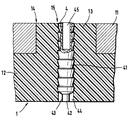
- a measuring tube 1 a flow sensor of a magnetic-inductive Flow meter shown. It comprises a metal tube 11 and an electrically conductive liquid flowing therein touching part 12, the volume flow is to be measured.
- the part 12 is electrically non-conductive, so it can e.g. from a suitable plastic or a suitable Rubber.
- It can also be a one-piece electrically non-conductive Measuring tube, so a completely from a suitable one Plastic, a suitable rubber or one suitable ceramic existing measuring tube can be used, if its wall thickness to accommodate a galvanic The electrode is sufficiently thick; in this case can therefore be dispensed with the metal tube 11.
- the electrically non-conductive extends Part 12 to form a cylindrical Approach 13 through a in the tube wall of the metal tube 11th attached bore 14 therethrough. It preferably has one constant diameter.
- the approach 13 has another Bore 15 with a compared to the diameter of the bore 14 smaller constant diameters.
- an electrode shaft 41 is in the bore 15 an electrode 4 3 contacting the liquid, which is inserted therein in such a way that an end face 42 of the electrode shaft 41 from the liquid in operation is wetted and the impedance of the electrode to the Properties and / or compared to the, especially current, Condition of the liquid and / or relative to the measuring tube, especially the capacitive component of the impedance is constant.
- the galvanic electrode 4 has one Electrode shaft 41 and an end face 42. In addition this is constant in all operating conditions permanent surface 43 of the electrode shaft 41 from the Liquid is constantly wetted.
- the material of the electrically non-conductive part 12 such a small Have surface tension that the liquid in the gap 44 penetrates completely, the surface of the Electrode shaft 41 preferably has a surface tension can have a lowering layer.
- the non-wetted part of the electrode shaft 41 is in the Bore 15 used liquid-tight, for which the usual Measures to be taken.
- One of them is in the figure shown, namely the electrode shaft 41 with one behind the other to provide lying frusto-conical sections, in which is the material in which the bore 15 is attached is clawed.
- the electrode shaft 41 has on its from the End face 42 facing away from a socket 45 for connection a lead to the electrode 4. It goes without saying also any other usual way of connecting the supply line possible with the electrode.
Landscapes
- Physics & Mathematics (AREA)
- Electromagnetism (AREA)
- Fluid Mechanics (AREA)
- General Physics & Mathematics (AREA)
- Measuring Volume Flow (AREA)
- Investigating Or Analyzing Materials By The Use Of Electric Means (AREA)
Priority Applications (1)
| Application Number | Priority Date | Filing Date | Title |
|---|---|---|---|
| EP98118525A EP0892252B1 (fr) | 1995-10-18 | 1996-06-04 | Electrodes galvaniques des débimètres électromagnétiques |
Applications Claiming Priority (4)
| Application Number | Priority Date | Filing Date | Title |
|---|---|---|---|
| EP95116405 | 1995-10-18 | ||
| EP95116405 | 1995-10-18 | ||
| EP96108893A EP0769680A1 (fr) | 1995-10-18 | 1996-06-04 | Electrodes galvaniques des débimètres électromagnétiques |
| EP98118525A EP0892252B1 (fr) | 1995-10-18 | 1996-06-04 | Electrodes galvaniques des débimètres électromagnétiques |
Related Parent Applications (1)
| Application Number | Title | Priority Date | Filing Date |
|---|---|---|---|
| EP96108893.7 Division | 1996-06-04 |
Related Child Applications (1)
| Application Number | Title | Priority Date | Filing Date |
|---|---|---|---|
| EP05021588.8 Division-Into | 2005-10-04 |
Publications (2)
| Publication Number | Publication Date |
|---|---|
| EP0892252A1 true EP0892252A1 (fr) | 1999-01-20 |
| EP0892252B1 EP0892252B1 (fr) | 2011-12-21 |
Family
ID=26138869
Family Applications (2)
| Application Number | Title | Priority Date | Filing Date |
|---|---|---|---|
| EP96108893A Withdrawn EP0769680A1 (fr) | 1995-10-18 | 1996-06-04 | Electrodes galvaniques des débimètres électromagnétiques |
| EP98118525A Expired - Lifetime EP0892252B1 (fr) | 1995-10-18 | 1996-06-04 | Electrodes galvaniques des débimètres électromagnétiques |
Family Applications Before (1)
| Application Number | Title | Priority Date | Filing Date |
|---|---|---|---|
| EP96108893A Withdrawn EP0769680A1 (fr) | 1995-10-18 | 1996-06-04 | Electrodes galvaniques des débimètres électromagnétiques |
Country Status (4)
| Country | Link |
|---|---|
| EP (2) | EP0769680A1 (fr) |
| JP (1) | JP2999422B2 (fr) |
| CN (1) | CN1097205C (fr) |
| DE (1) | DE29623770U1 (fr) |
Cited By (5)
| Publication number | Priority date | Publication date | Assignee | Title |
|---|---|---|---|---|
| WO2008059020A1 (fr) | 2006-11-17 | 2008-05-22 | Endress+Hauser Flowtec Ag | Dispositif de mesure du débit volumique ou du débit massique d'un milieu dans un conduit |
| WO2008074740A1 (fr) * | 2006-12-19 | 2008-06-26 | Endress+Hauser Flowtec Ag | Dispositif pour mesurer le débit volumétrique ou massique d'un milieu dans une canalisation |
| DE102007058898A1 (de) | 2007-12-05 | 2009-06-10 | Endress + Hauser Flowtec Ag | Elektrode für ein magnetisch-induktives Durchflussmessgerät |
| DE202015103218U1 (de) | 2015-06-18 | 2015-08-19 | Endress + Hauser Flowtec Ag | Anordnung und Durchflussmessgerät |
| US9228868B2 (en) | 2013-08-28 | 2016-01-05 | Sensus Spectrum Llc | Magnetically inductive flowmeter for determining the flow rate of a fluid flowing through a measuring tube |
Families Citing this family (4)
| Publication number | Priority date | Publication date | Assignee | Title |
|---|---|---|---|---|
| US6598487B1 (en) * | 2002-05-20 | 2003-07-29 | Marsh-Mcbirney, Inc. | Magnetic flowmeter having a separable magnet/electrode assembly |
| DE102008059067A1 (de) | 2008-11-26 | 2010-06-02 | Krohne Ag | Magnetisch-induktives Durchflußmeßgerät |
| US10031008B2 (en) | 2016-06-02 | 2018-07-24 | Sensus USA, Inc. | Electromagnetic flow meter |
| GB201911971D0 (en) * | 2019-08-21 | 2019-10-02 | Sentec Ltd | Improved electrode |
Citations (5)
| Publication number | Priority date | Publication date | Assignee | Title |
|---|---|---|---|---|
| GB1153295A (en) * | 1965-09-02 | 1969-05-29 | Mawdsley S Ltd | Improvements in or relating to sealing arrangements for electrodes. |
| GB2047409A (en) * | 1979-03-21 | 1980-11-26 | Davies P M | Electrodes for electromagnetic flowmeters |
| GB2057692A (en) * | 1979-08-09 | 1981-04-01 | Emerson Electric Co | Field Replaceable Electrode Assembly for Magnetic Flowmeter |
| US4773275A (en) * | 1986-05-27 | 1988-09-27 | The Foxboro Company | Seal for ceramic flow tube |
| US5095759A (en) * | 1990-06-01 | 1992-03-17 | Gte Products Corporation | Platinum electrode bonded to ceramic |
Family Cites Families (3)
| Publication number | Priority date | Publication date | Assignee | Title |
|---|---|---|---|---|
| JPS5799121U (fr) * | 1980-12-09 | 1982-06-18 | ||
| JP2887336B2 (ja) * | 1992-11-25 | 1999-04-26 | 松下電工株式会社 | 非接触式スイッチ |
| JPH06308104A (ja) * | 1993-04-28 | 1994-11-04 | Toshiba Corp | 超音波プローブ |
-
1996
- 1996-06-04 EP EP96108893A patent/EP0769680A1/fr not_active Withdrawn
- 1996-06-04 DE DE29623770U patent/DE29623770U1/de not_active Expired - Lifetime
- 1996-06-04 EP EP98118525A patent/EP0892252B1/fr not_active Expired - Lifetime
- 1996-10-09 JP JP8268198A patent/JP2999422B2/ja not_active Expired - Fee Related
- 1996-10-10 CN CN 96122631 patent/CN1097205C/zh not_active Expired - Lifetime
Patent Citations (5)
| Publication number | Priority date | Publication date | Assignee | Title |
|---|---|---|---|---|
| GB1153295A (en) * | 1965-09-02 | 1969-05-29 | Mawdsley S Ltd | Improvements in or relating to sealing arrangements for electrodes. |
| GB2047409A (en) * | 1979-03-21 | 1980-11-26 | Davies P M | Electrodes for electromagnetic flowmeters |
| GB2057692A (en) * | 1979-08-09 | 1981-04-01 | Emerson Electric Co | Field Replaceable Electrode Assembly for Magnetic Flowmeter |
| US4773275A (en) * | 1986-05-27 | 1988-09-27 | The Foxboro Company | Seal for ceramic flow tube |
| US5095759A (en) * | 1990-06-01 | 1992-03-17 | Gte Products Corporation | Platinum electrode bonded to ceramic |
Cited By (7)
| Publication number | Priority date | Publication date | Assignee | Title |
|---|---|---|---|---|
| WO2008059020A1 (fr) | 2006-11-17 | 2008-05-22 | Endress+Hauser Flowtec Ag | Dispositif de mesure du débit volumique ou du débit massique d'un milieu dans un conduit |
| US8051722B2 (en) | 2006-11-17 | 2011-11-08 | Endress+ Hauser Flowtec Ag | Apparatus for measuring volume- or mass-flow of a medium in a pipeline |
| WO2008074740A1 (fr) * | 2006-12-19 | 2008-06-26 | Endress+Hauser Flowtec Ag | Dispositif pour mesurer le débit volumétrique ou massique d'un milieu dans une canalisation |
| DE102007058898A1 (de) | 2007-12-05 | 2009-06-10 | Endress + Hauser Flowtec Ag | Elektrode für ein magnetisch-induktives Durchflussmessgerät |
| US8375806B2 (en) | 2007-12-05 | 2013-02-19 | Endress + Hauser Flowtec Ag | Electrode shaft for a magneto-inductive flow measuring device having a plurality of frustoconical sealing lips |
| US9228868B2 (en) | 2013-08-28 | 2016-01-05 | Sensus Spectrum Llc | Magnetically inductive flowmeter for determining the flow rate of a fluid flowing through a measuring tube |
| DE202015103218U1 (de) | 2015-06-18 | 2015-08-19 | Endress + Hauser Flowtec Ag | Anordnung und Durchflussmessgerät |
Also Published As
| Publication number | Publication date |
|---|---|
| CN1097205C (zh) | 2002-12-25 |
| CN1164641A (zh) | 1997-11-12 |
| JP2999422B2 (ja) | 2000-01-17 |
| EP0892252B1 (fr) | 2011-12-21 |
| DE29623770U1 (de) | 1999-08-26 |
| JPH09126844A (ja) | 1997-05-16 |
| EP0769680A1 (fr) | 1997-04-23 |
Similar Documents
| Publication | Publication Date | Title |
|---|---|---|
| EP2422167B1 (fr) | Procédé pour faire fonctionner un débitmètre magnéto-inductif | |
| EP2338035B1 (fr) | Procédé permettant de faire fonctionner avec économie d'énergie un appareil débitmétrique à induction magnétique | |
| DE102013014223B4 (de) | Magnetisch induktiver Durchflussmesser zur Bestimmung des Durchflusses eines durch ein Messrohr hindurchströmenden Fluids | |
| DE102007058898A1 (de) | Elektrode für ein magnetisch-induktives Durchflussmessgerät | |
| EP4147012A1 (fr) | Dispositif de mesure de débit à induction magnétique et procédé de détermination d'un niveau de remplissage | |
| EP0892252B1 (fr) | Electrodes galvaniques des débimètres électromagnétiques | |
| DE102010032270B4 (de) | Magnetisch-induktives Durchflussmessgerät | |
| WO2020114720A1 (fr) | Débitmètre magnéto-inductif | |
| WO2007110310A1 (fr) | Débitmètre magnétique à induction | |
| DE102005028723A1 (de) | Magnetisch-induktives Durchflussmessgerät | |
| DE102019123359A1 (de) | Magnetisch-induktive Durchflussmesssonde und Verfahren zum Betreiben einer magnetisch-induktiven Durchflussmesssonde | |
| DE3323798C2 (fr) | ||
| DE2950084C2 (de) | Magnetisch-induktiver Durchflußmesser | |
| EP0977018B1 (fr) | Arrangement d'électrodes pour débitmètres magnéto-inductives | |
| EP1994370B1 (fr) | Équilibrage des potentiels entre un fluide et le capteur de mesure d'un débitmètre | |
| EP1193474A1 (fr) | Dispositif de mesure d' écoulements pour la détection magnétique-inductive ou capacitive des débits | |
| DE3712948C2 (de) | Elektrode für einen magnetisch-induktiven Durchflußmesser | |
| DE10335205A1 (de) | Verfahren zur magnetisch-induktiven Bestimmung der Durchflußrate eines Mediums | |
| EP3899438A1 (fr) | Sonde de mesure de débit à induction magnétique, structure de mesure et procédé de détermination d'un débit et/ou d'un angle de montage | |
| DE3435910C2 (de) | Magnetisch-induktiver Durchflußmesser mit auswechselbaren Durchflußsensoren | |
| EP3870938A1 (fr) | Débitmètre magnéto-inductif | |
| DE102018132603A1 (de) | Magnetisch-induktive Durchflussmesssonde, Messaufbau und Verfahren zur Ermittlung eines Durchflusses und/oder eines Einbauwinkels | |
| DE202015103218U1 (de) | Anordnung und Durchflussmessgerät | |
| DE3630885A1 (de) | Induktiver durchflussmesser | |
| DE102024118322A1 (de) | Verfahren zum Betreiben eines magnetisch-induktiven Durchflussmessgeräts und magnetisch-induktives Durchflussmessgerät |
Legal Events
| Date | Code | Title | Description |
|---|---|---|---|
| PUAI | Public reference made under article 153(3) epc to a published international application that has entered the european phase |
Free format text: ORIGINAL CODE: 0009012 |
|
| 17P | Request for examination filed |
Effective date: 19980930 |
|
| AC | Divisional application: reference to earlier application |
Ref document number: 769680 Country of ref document: EP |
|
| AK | Designated contracting states |
Kind code of ref document: A1 Designated state(s): CH DE DK ES FR GB IT LI NL |
|
| 18D | Application deemed to be withdrawn |
Effective date: 19990721 |
|
| D18D | Application deemed to be withdrawn (deleted) | ||
| 17Q | First examination report despatched |
Effective date: 20020710 |
|
| APBR | Date of receipt of statement of grounds of appeal recorded |
Free format text: ORIGINAL CODE: EPIDOSNNOA3E |
|
| APAF | Appeal reference modified |
Free format text: ORIGINAL CODE: EPIDOSCREFNE |
|
| APBT | Appeal procedure closed |
Free format text: ORIGINAL CODE: EPIDOSNNOA9E |
|
| GRAP | Despatch of communication of intention to grant a patent |
Free format text: ORIGINAL CODE: EPIDOSNIGR1 |
|
| GRAS | Grant fee paid |
Free format text: ORIGINAL CODE: EPIDOSNIGR3 |
|
| GRAA | (expected) grant |
Free format text: ORIGINAL CODE: 0009210 |
|
| AC | Divisional application: reference to earlier application |
Ref document number: 0769680 Country of ref document: EP Kind code of ref document: P |
|
| AK | Designated contracting states |
Kind code of ref document: B1 Designated state(s): CH DE DK ES FR GB IT LI NL |
|
| REG | Reference to a national code |
Ref country code: CH Ref legal event code: EP |
|
| REG | Reference to a national code |
Ref country code: DE Ref legal event code: R096 Ref document number: 59611522 Country of ref document: DE Effective date: 20120301 |
|
| REG | Reference to a national code |
Ref country code: NL Ref legal event code: T3 |
|
| PLBE | No opposition filed within time limit |
Free format text: ORIGINAL CODE: 0009261 |
|
| STAA | Information on the status of an ep patent application or granted ep patent |
Free format text: STATUS: NO OPPOSITION FILED WITHIN TIME LIMIT |
|
| PG25 | Lapsed in a contracting state [announced via postgrant information from national office to epo] |
Ref country code: DK Free format text: LAPSE BECAUSE OF FAILURE TO SUBMIT A TRANSLATION OF THE DESCRIPTION OR TO PAY THE FEE WITHIN THE PRESCRIBED TIME-LIMIT Effective date: 20111221 |
|
| 26N | No opposition filed |
Effective date: 20120924 |
|
| REG | Reference to a national code |
Ref country code: DE Ref legal event code: R097 Ref document number: 59611522 Country of ref document: DE Effective date: 20120924 |
|
| GBPC | Gb: european patent ceased through non-payment of renewal fee |
Effective date: 20120604 |
|
| REG | Reference to a national code |
Ref country code: FR Ref legal event code: ST Effective date: 20130228 |
|
| PG25 | Lapsed in a contracting state [announced via postgrant information from national office to epo] |
Ref country code: GB Free format text: LAPSE BECAUSE OF NON-PAYMENT OF DUE FEES Effective date: 20120604 Ref country code: ES Free format text: LAPSE BECAUSE OF FAILURE TO SUBMIT A TRANSLATION OF THE DESCRIPTION OR TO PAY THE FEE WITHIN THE PRESCRIBED TIME-LIMIT Effective date: 20120401 Ref country code: FR Free format text: LAPSE BECAUSE OF NON-PAYMENT OF DUE FEES Effective date: 20120702 |
|
| PGFP | Annual fee paid to national office [announced via postgrant information from national office to epo] |
Ref country code: CH Payment date: 20130621 Year of fee payment: 18 |
|
| PGFP | Annual fee paid to national office [announced via postgrant information from national office to epo] |
Ref country code: NL Payment date: 20130619 Year of fee payment: 18 |
|
| REG | Reference to a national code |
Ref country code: NL Ref legal event code: V1 Effective date: 20150101 |
|
| REG | Reference to a national code |
Ref country code: CH Ref legal event code: PL |
|
| PG25 | Lapsed in a contracting state [announced via postgrant information from national office to epo] |
Ref country code: NL Free format text: LAPSE BECAUSE OF NON-PAYMENT OF DUE FEES Effective date: 20150101 |
|
| PG25 | Lapsed in a contracting state [announced via postgrant information from national office to epo] |
Ref country code: LI Free format text: LAPSE BECAUSE OF NON-PAYMENT OF DUE FEES Effective date: 20140630 Ref country code: CH Free format text: LAPSE BECAUSE OF NON-PAYMENT OF DUE FEES Effective date: 20140630 |
|
| PGFP | Annual fee paid to national office [announced via postgrant information from national office to epo] |
Ref country code: DE Payment date: 20150619 Year of fee payment: 20 |
|
| PGFP | Annual fee paid to national office [announced via postgrant information from national office to epo] |
Ref country code: IT Payment date: 20150622 Year of fee payment: 20 |
|
| REG | Reference to a national code |
Ref country code: DE Ref legal event code: R071 Ref document number: 59611522 Country of ref document: DE |