EP0892253A1 - Débitmètre à piston rotatif - Google Patents
Débitmètre à piston rotatif Download PDFInfo
- Publication number
- EP0892253A1 EP0892253A1 EP98109965A EP98109965A EP0892253A1 EP 0892253 A1 EP0892253 A1 EP 0892253A1 EP 98109965 A EP98109965 A EP 98109965A EP 98109965 A EP98109965 A EP 98109965A EP 0892253 A1 EP0892253 A1 EP 0892253A1
- Authority
- EP
- European Patent Office
- Prior art keywords
- piston
- measuring chamber
- outlet opening
- jacket
- sealing strip
- Prior art date
- Legal status (The legal status is an assumption and is not a legal conclusion. Google has not performed a legal analysis and makes no representation as to the accuracy of the status listed.)
- Granted
Links
- 238000005192 partition Methods 0.000 claims abstract description 12
- 238000007789 sealing Methods 0.000 claims description 29
- 238000005259 measurement Methods 0.000 abstract description 8
- XLYOFNOQVPJJNP-UHFFFAOYSA-N water Substances O XLYOFNOQVPJJNP-UHFFFAOYSA-N 0.000 abstract description 3
- 238000000465 moulding Methods 0.000 abstract 1
- 239000007788 liquid Substances 0.000 description 13
- 238000000034 method Methods 0.000 description 3
- 230000001133 acceleration Effects 0.000 description 1
- 230000006866 deterioration Effects 0.000 description 1
- 230000000694 effects Effects 0.000 description 1
- 239000012530 fluid Substances 0.000 description 1
- 230000005484 gravity Effects 0.000 description 1
- 230000008092 positive effect Effects 0.000 description 1
- 238000005381 potential energy Methods 0.000 description 1
Images



Classifications
-
- G—PHYSICS
- G01—MEASURING; TESTING
- G01F—MEASURING VOLUME, VOLUME FLOW, MASS FLOW OR LIQUID LEVEL; METERING BY VOLUME
- G01F3/00—Measuring the volume flow of fluids or fluent solid material wherein the fluid passes through the meter in successive and more or less isolated quantities, the meter being driven by the flow
- G01F3/02—Measuring the volume flow of fluids or fluent solid material wherein the fluid passes through the meter in successive and more or less isolated quantities, the meter being driven by the flow with measuring chambers which expand or contract during measurement
- G01F3/04—Measuring the volume flow of fluids or fluent solid material wherein the fluid passes through the meter in successive and more or less isolated quantities, the meter being driven by the flow with measuring chambers which expand or contract during measurement having rigid movable walls
- G01F3/06—Measuring the volume flow of fluids or fluent solid material wherein the fluid passes through the meter in successive and more or less isolated quantities, the meter being driven by the flow with measuring chambers which expand or contract during measurement having rigid movable walls comprising members rotating in a fluid-tight or substantially fluid-tight manner in a housing
- G01F3/08—Rotary-piston or ring-piston meters
Definitions
- the invention relates to rotary piston meters according to the preamble of claim 1.
- Rotary piston meters which belong to the immediate volume meters, have one Measuring chamber that inevitably flows through the entire amount of liquid becomes. Part of the potential energy of the liquid to be measured goes for lost the drive of the counter. The resulting pressure drop is called Pressure loss delta p. It arises from water diversions, Cross-sectional changes along the flow path, drive of the ring piston, etc.
- the ring piston In the measuring chamber there is the ring piston, which during the measuring process of the high pressure side is pushed to the low pressure side. This happens automatically through the fluid flow. With one revolution of the ring piston two different volumes of constant and specific size transported. The ring piston moves with its lower piston pin around the center pin of the measuring chamber.
- the jacket of the ring piston is slotted over its entire height. That slit moves back and forth along each time the ring piston rotates a partition in the measuring chamber.
- the oscillating movement has the advantage of automatic return of the ring piston to its starting position without the help of additional reversing devices, valves, slides, etc. Through the inner and outer piston guide, the movement of the ring piston is inevitable.
- a driver is driven by the upper piston pin of the ring piston, which drives the transmits circular movements of the pin on a counter.
- the measuring accuracy of the ring piston meter largely depends on the dimensional accuracy the measuring chamber parts.
- there must be a minimum clearance between the ring piston and Measuring chamber must be present so that the ring piston does not jam.
- Typical values for the gaps between the moving parts are less than or equal to 10 ⁇ m.
- the liquid flows through a crescent-shaped opening in the Bottom of the measuring chamber and through a 'further crescent-shaped opening in the bottom the measuring chamber again.
- the flow exerts one-sided forces on the Ring piston, so that it experiences increased friction and wear. Both affects the measuring accuracy negatively.
- the liquid to be measured flows through a crescent-shaped opening in the bottom of the measuring chamber and through a likewise sickle-shaped opening in the cover of the measuring chamber.
- Inlet and Outlet openings can also switch positions.
- the annular piston exerted one-sided forces, which made measuring accuracy unfavorable influence.
- the present invention relates to ring piston meters with a liquid guide according to variant three.
- the present invention has for its object the measurement errors of to reduce the generic ring piston counter.
- the sealing strips according to the invention only ensure that the briefly opening additional gaps remain closed in the manner of a labyrinth seal, as a result of which the effective gap area "A gap " and with it the gap losses "Q gap " decrease and the measuring accuracy increases significantly.
- the outer sealing strip is on the Measuring chamber attached and protrudes into the outlet opening of the annular piston.
- the outer sealing strip is attached to the ring piston and protrudes into the outlet opening of the measuring chamber.
- the inner sealing strip is on the outer wall of the Guide ring attached and protrudes into the outlet opening of the annular piston.
- the sealing strips are advantageously molded in one piece.
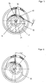
- Fig. 1 shows a plan view of the parts required for explaining the invention a ring piston counter.
- Outlet opening 17 incorporated in the form of a rectangular slot.
- An annular piston 30, formed from, can be seen in the interior of the measuring chamber 10 a cylindrical piston skirt 31, a piston crown 32 and a Guide pin 33.
- the guide pin 33 moves in a circular path around the Center pin 13.
- a radial slot 34 is machined into the piston skirt 31 and piston crown 32, thanks to which the annular piston 30 can be plugged onto the partition 15. Due to the straight line caused by the partition 15 in combination with the by means of center pin 13 and guide ring 14 effected circular guidance Ring piston 30 the known oscillating movement.
- FIG 3 shows a first solution for eliminating the additional gap A1.
- a sealing strip 1 formed at the Inner wall 20 of the measuring chamber jacket 12 is in the region of the side wall 19 and this extends a sealing strip 1 formed. This appears immediately next to the Side wall 38 of the outlet opening 36 in the piston skirt 31 into the outlet opening 36 on. This creates a kind of labyrinth seal that seals gap A1.
- Fig. 4 shows a second solution for sealing the additional gap A1.
- a Sealing strip 2 is in the extension of the side wall 38 of the outlet opening 36 on Piston jacket 31 molded and immersed in the outlet opening 17 in Measuring chamber jacket 12 a.
- This solution has the additional advantage that the Sealing strip 2, the flow of the outer measuring volume V1 in the direction of Exhaust opening 17 deflects so that not only the gap losses, but also the Flow losses are reduced '.
- FIG. 5 shows the ring piston counter of FIG. 1, but the ring piston 30 has moved 180 °.
- the annular piston 30 reaches the angular position ⁇ 'in FIG. 6 shown, reached, an additional gap is formed, which in the piston position as in Fig. 5 shows its maximum size A1 'reached.
- a subset of the Chamber volume V2 flows unmeasured through the gap A1 '.
- Fig. 7 shows a solution, as well as the second additional gap A1 'using a Sealing strip 3, molded onto the inside of the piston skirt 31, sealed can be.
- a groove 22 is incorporated in the guide cylinder 14, in which the immersed inner sealing strip 3.
- the outer sealing strip 2 can be seen in the extension of the inner sealing strip 3.
Landscapes
- Physics & Mathematics (AREA)
- Fluid Mechanics (AREA)
- General Physics & Mathematics (AREA)
- Measuring Volume Flow (AREA)
Applications Claiming Priority (2)
| Application Number | Priority Date | Filing Date | Title |
|---|---|---|---|
| DE19730605 | 1997-07-17 | ||
| DE1997130605 DE19730605C1 (de) | 1997-07-17 | 1997-07-17 | Ringkolbenzähler |
Publications (2)
| Publication Number | Publication Date |
|---|---|
| EP0892253A1 true EP0892253A1 (fr) | 1999-01-20 |
| EP0892253B1 EP0892253B1 (fr) | 2002-03-27 |
Family
ID=7835970
Family Applications (1)
| Application Number | Title | Priority Date | Filing Date |
|---|---|---|---|
| EP19980109965 Expired - Lifetime EP0892253B1 (fr) | 1997-07-17 | 1998-06-02 | Débitmètre à piston rotatif |
Country Status (4)
| Country | Link |
|---|---|
| EP (1) | EP0892253B1 (fr) |
| CA (1) | CA2243337C (fr) |
| DE (1) | DE19730605C1 (fr) |
| ES (1) | ES2173528T3 (fr) |
Families Citing this family (1)
| Publication number | Priority date | Publication date | Assignee | Title |
|---|---|---|---|---|
| DE102009009737A1 (de) | 2009-02-19 | 2010-08-26 | M & Fc Holding Llc | Verbrauchszähler für Flüssigkeiten |
Citations (3)
| Publication number | Priority date | Publication date | Assignee | Title |
|---|---|---|---|---|
| FR454609A (fr) * | 1913-02-20 | 1913-07-09 | Compteurs Comp D | Compteur d'eau à piston rotatif |
| EP0153446A1 (fr) * | 1984-02-27 | 1985-09-04 | Rockwell International Corporation | Embrayage pour compteurs à liquide |
| WO1994007111A1 (fr) * | 1992-09-22 | 1994-03-31 | Abb Kent Plc | Compteurs d'eau volumetriques et pompes |
Family Cites Families (1)
| Publication number | Priority date | Publication date | Assignee | Title |
|---|---|---|---|---|
| FR2719663B1 (fr) * | 1994-05-06 | 1996-07-19 | Soc Dapplications Mecaniques Et Electriques De Boulogne Billancourt Sappel | Dispositif de mesure pour compteur de liquide a piston oscillant |
-
1997
- 1997-07-17 DE DE1997130605 patent/DE19730605C1/de not_active Expired - Fee Related
-
1998
- 1998-06-02 ES ES98109965T patent/ES2173528T3/es not_active Expired - Lifetime
- 1998-06-02 EP EP19980109965 patent/EP0892253B1/fr not_active Expired - Lifetime
- 1998-07-16 CA CA 2243337 patent/CA2243337C/fr not_active Expired - Fee Related
Patent Citations (3)
| Publication number | Priority date | Publication date | Assignee | Title |
|---|---|---|---|---|
| FR454609A (fr) * | 1913-02-20 | 1913-07-09 | Compteurs Comp D | Compteur d'eau à piston rotatif |
| EP0153446A1 (fr) * | 1984-02-27 | 1985-09-04 | Rockwell International Corporation | Embrayage pour compteurs à liquide |
| WO1994007111A1 (fr) * | 1992-09-22 | 1994-03-31 | Abb Kent Plc | Compteurs d'eau volumetriques et pompes |
Also Published As
| Publication number | Publication date |
|---|---|
| DE19730605C1 (de) | 1998-08-27 |
| CA2243337C (fr) | 2001-09-11 |
| CA2243337A1 (fr) | 1999-01-17 |
| EP0892253B1 (fr) | 2002-03-27 |
| ES2173528T3 (es) | 2002-10-16 |
Similar Documents
| Publication | Publication Date | Title |
|---|---|---|
| DE69021545T2 (de) | Reibungsfreier rotationsmotorpumpenmesser. | |
| AT400766B (de) | Einrichtung zur volumenmessung strömender medien | |
| DE3236536A1 (de) | Hydraulische hochdruckpumpe | |
| EP0892253B1 (fr) | Débitmètre à piston rotatif | |
| EP0491246B1 (fr) | Capteur du volume pour fluides | |
| EP1654464B1 (fr) | Dispositif d'amortissement de coups de belier | |
| DE2446416C3 (de) | DurchfluBmesser | |
| DE900639C (de) | Korrektionsvorrichtung fuer Viskositaetsschwankungen in Fluessigkeitsstossdaempfern | |
| EP0895067B1 (fr) | Débitmètre à piston rotatif | |
| DE3236392C2 (de) | Durchflußmeßvorrichtung | |
| DE3923142C2 (de) | Flügelradzähler zum Messen einer Flüssigkeitsmenge | |
| DE2458699A1 (de) | Nach dem verdraengerprinzip arbeitender rotations-durchflussmesser fuer fluide | |
| DE3226611A1 (de) | Durchflussmessgeraet | |
| DE2033168A1 (de) | Mischvorrichtung | |
| EP0180944B1 (fr) | Dispositif pour la mesure du débit d'un fluide | |
| DE3119089A1 (de) | Pneumatisches zeitglied | |
| DE102017001315A1 (de) | Adaptierbarer Nebenzähler für einen Verbundzähler zur Durchflussbestimmung eines strömenden Mediums | |
| DE2128081A1 (de) | Strömungsanzeigegerät | |
| EP0281126B1 (fr) | Dispositif pour mesurer ou doser des matériaux fluides | |
| DE19839952C1 (de) | Durchfluß-Meßvorrichtung | |
| EP0794412B1 (fr) | Appareil de mesure de quantités de liquide à piston rotatif | |
| DE2017636A1 (de) | Fluidumlenkvorrichtung, insbesondere Fluidumlenkventil | |
| DE19717794C2 (de) | Verdrängerpumpe | |
| DE4432275C1 (de) | Vorrichtung zur Volumenmessung von Flüssigkeiten nach Art eines Ringkolbenzählers | |
| DE2456388A1 (de) | Dosiervorrichtung |
Legal Events
| Date | Code | Title | Description |
|---|---|---|---|
| PUAI | Public reference made under article 153(3) epc to a published international application that has entered the european phase |
Free format text: ORIGINAL CODE: 0009012 |
|
| AK | Designated contracting states |
Kind code of ref document: A1 Designated state(s): BE ES FR GB IT |
|
| AX | Request for extension of the european patent |
Free format text: AL;LT;LV;MK;RO;SI |
|
| 17P | Request for examination filed |
Effective date: 19990409 |
|
| AKX | Designation fees paid |
Free format text: BE ES FR GB IT |
|
| REG | Reference to a national code |
Ref country code: DE Ref legal event code: 8566 |
|
| GRAG | Despatch of communication of intention to grant |
Free format text: ORIGINAL CODE: EPIDOS AGRA |
|
| 17Q | First examination report despatched |
Effective date: 20010625 |
|
| GRAG | Despatch of communication of intention to grant |
Free format text: ORIGINAL CODE: EPIDOS AGRA |
|
| GRAH | Despatch of communication of intention to grant a patent |
Free format text: ORIGINAL CODE: EPIDOS IGRA |
|
| GRAH | Despatch of communication of intention to grant a patent |
Free format text: ORIGINAL CODE: EPIDOS IGRA |
|
| REG | Reference to a national code |
Ref country code: GB Ref legal event code: IF02 |
|
| GRAA | (expected) grant |
Free format text: ORIGINAL CODE: 0009210 |
|
| AK | Designated contracting states |
Kind code of ref document: B1 Designated state(s): BE ES FR GB IT |
|
| GBT | Gb: translation of ep patent filed (gb section 77(6)(a)/1977) |
Effective date: 20020618 |
|
| ET | Fr: translation filed | ||
| REG | Reference to a national code |
Ref country code: ES Ref legal event code: FG2A Ref document number: 2173528 Country of ref document: ES Kind code of ref document: T3 |
|
| PLBE | No opposition filed within time limit |
Free format text: ORIGINAL CODE: 0009261 |
|
| STAA | Information on the status of an ep patent application or granted ep patent |
Free format text: STATUS: NO OPPOSITION FILED WITHIN TIME LIMIT |
|
| 26N | No opposition filed |
Effective date: 20021230 |
|
| REG | Reference to a national code |
Ref country code: FR Ref legal event code: CD |
|
| BECH | Be: change of holder |
Owner name: *M & FC HOLDING LLC Effective date: 20050706 |
|
| REG | Reference to a national code |
Ref country code: GB Ref legal event code: 732E |
|
| REG | Reference to a national code |
Ref country code: FR Ref legal event code: TP Ref country code: FR Ref legal event code: CD |
|
| BECH | Be: change of holder |
Owner name: *M & FC HOLDING LLC Effective date: 20050706 |
|
| PGFP | Annual fee paid to national office [announced via postgrant information from national office to epo] |
Ref country code: ES Payment date: 20091029 Year of fee payment: 12 |
|
| PGFP | Annual fee paid to national office [announced via postgrant information from national office to epo] |
Ref country code: IT Payment date: 20091027 Year of fee payment: 12 |
|
| PG25 | Lapsed in a contracting state [announced via postgrant information from national office to epo] |
Ref country code: IT Free format text: LAPSE BECAUSE OF NON-PAYMENT OF DUE FEES Effective date: 20100602 |
|
| REG | Reference to a national code |
Ref country code: ES Ref legal event code: FD2A Effective date: 20111118 |
|
| PG25 | Lapsed in a contracting state [announced via postgrant information from national office to epo] |
Ref country code: ES Free format text: LAPSE BECAUSE OF NON-PAYMENT OF DUE FEES Effective date: 20100603 |
|
| PGFP | Annual fee paid to national office [announced via postgrant information from national office to epo] |
Ref country code: GB Payment date: 20120723 Year of fee payment: 15 |
|
| PGFP | Annual fee paid to national office [announced via postgrant information from national office to epo] |
Ref country code: BE Payment date: 20120724 Year of fee payment: 15 Ref country code: FR Payment date: 20120803 Year of fee payment: 15 |
|
| BERE | Be: lapsed |
Owner name: *M & FC HOLDING LLC Effective date: 20130630 |
|
| GBPC | Gb: european patent ceased through non-payment of renewal fee |
Effective date: 20130602 |
|
| REG | Reference to a national code |
Ref country code: FR Ref legal event code: ST Effective date: 20140228 |
|
| PG25 | Lapsed in a contracting state [announced via postgrant information from national office to epo] |
Ref country code: BE Free format text: LAPSE BECAUSE OF NON-PAYMENT OF DUE FEES Effective date: 20130630 |
|
| PG25 | Lapsed in a contracting state [announced via postgrant information from national office to epo] |
Ref country code: GB Free format text: LAPSE BECAUSE OF NON-PAYMENT OF DUE FEES Effective date: 20130602 |
|
| PG25 | Lapsed in a contracting state [announced via postgrant information from national office to epo] |
Ref country code: FR Free format text: LAPSE BECAUSE OF NON-PAYMENT OF DUE FEES Effective date: 20130701 |