EP0892281B1 - Verfahren und Vorrichtung zur Erfassung der Fahrsituation eines Kraftfahrzeuges - Google Patents
Verfahren und Vorrichtung zur Erfassung der Fahrsituation eines Kraftfahrzeuges Download PDFInfo
- Publication number
- EP0892281B1 EP0892281B1 EP98110908A EP98110908A EP0892281B1 EP 0892281 B1 EP0892281 B1 EP 0892281B1 EP 98110908 A EP98110908 A EP 98110908A EP 98110908 A EP98110908 A EP 98110908A EP 0892281 B1 EP0892281 B1 EP 0892281B1
- Authority
- EP
- European Patent Office
- Prior art keywords
- determined
- distance sensor
- sensor system
- sensed
- reference values
- Prior art date
- Legal status (The legal status is an assumption and is not a legal conclusion. Google has not performed a legal analysis and makes no representation as to the accuracy of the status listed.)
- Expired - Lifetime
Links
Images
Classifications
-
- G—PHYSICS
- G01—MEASURING; TESTING
- G01S—RADIO DIRECTION-FINDING; RADIO NAVIGATION; DETERMINING DISTANCE OR VELOCITY BY USE OF RADIO WAVES; LOCATING OR PRESENCE-DETECTING BY USE OF THE REFLECTION OR RERADIATION OF RADIO WAVES; ANALOGOUS ARRANGEMENTS USING OTHER WAVES
- G01S13/00—Systems using the reflection or reradiation of radio waves, e.g. radar systems; Analogous systems using reflection or reradiation of waves whose nature or wavelength is irrelevant or unspecified
- G01S13/88—Radar or analogous systems specially adapted for specific applications
- G01S13/93—Radar or analogous systems specially adapted for specific applications for anti-collision purposes
- G01S13/931—Radar or analogous systems specially adapted for specific applications for anti-collision purposes of land vehicles
-
- B—PERFORMING OPERATIONS; TRANSPORTING
- B60—VEHICLES IN GENERAL
- B60K—ARRANGEMENT OR MOUNTING OF PROPULSION UNITS OR OF TRANSMISSIONS IN VEHICLES; ARRANGEMENT OR MOUNTING OF PLURAL DIVERSE PRIME-MOVERS IN VEHICLES; AUXILIARY DRIVES FOR VEHICLES; INSTRUMENTATION OR DASHBOARDS FOR VEHICLES; ARRANGEMENTS IN CONNECTION WITH COOLING, AIR INTAKE, GAS EXHAUST OR FUEL SUPPLY OF PROPULSION UNITS IN VEHICLES
- B60K31/00—Vehicle fittings, acting on a single sub-unit only, for automatically controlling vehicle speed, i.e. preventing speed from exceeding an arbitrarily established velocity or maintaining speed at a particular velocity, as selected by the vehicle operator
- B60K31/0008—Vehicle fittings, acting on a single sub-unit only, for automatically controlling vehicle speed, i.e. preventing speed from exceeding an arbitrarily established velocity or maintaining speed at a particular velocity, as selected by the vehicle operator including means for detecting potential obstacles in vehicle path
-
- G—PHYSICS
- G08—SIGNALLING
- G08G—TRAFFIC CONTROL SYSTEMS
- G08G1/00—Traffic control systems for road vehicles
- G08G1/01—Detecting movement of traffic to be counted or controlled
-
- B—PERFORMING OPERATIONS; TRANSPORTING
- B60—VEHICLES IN GENERAL
- B60W—CONJOINT CONTROL OF VEHICLE SUB-UNITS OF DIFFERENT TYPE OR DIFFERENT FUNCTION; CONTROL SYSTEMS SPECIALLY ADAPTED FOR HYBRID VEHICLES; ROAD VEHICLE DRIVE CONTROL SYSTEMS FOR PURPOSES NOT RELATED TO THE CONTROL OF A PARTICULAR SUB-UNIT
- B60W2552/00—Input parameters relating to infrastructure
- B60W2552/05—Type of road, e.g. motorways, local streets, paved or unpaved roads
-
- B—PERFORMING OPERATIONS; TRANSPORTING
- B60—VEHICLES IN GENERAL
- B60W—CONJOINT CONTROL OF VEHICLE SUB-UNITS OF DIFFERENT TYPE OR DIFFERENT FUNCTION; CONTROL SYSTEMS SPECIALLY ADAPTED FOR HYBRID VEHICLES; ROAD VEHICLE DRIVE CONTROL SYSTEMS FOR PURPOSES NOT RELATED TO THE CONTROL OF A PARTICULAR SUB-UNIT
- B60W2552/00—Input parameters relating to infrastructure
- B60W2552/10—Number of lanes
-
- F—MECHANICAL ENGINEERING; LIGHTING; HEATING; WEAPONS; BLASTING
- F02—COMBUSTION ENGINES; HOT-GAS OR COMBUSTION-PRODUCT ENGINE PLANTS
- F02D—CONTROLLING COMBUSTION ENGINES
- F02D2200/00—Input parameters for engine control
- F02D2200/70—Input parameters for engine control said parameters being related to the vehicle exterior
- F02D2200/702—Road conditions
-
- G—PHYSICS
- G01—MEASURING; TESTING
- G01S—RADIO DIRECTION-FINDING; RADIO NAVIGATION; DETERMINING DISTANCE OR VELOCITY BY USE OF RADIO WAVES; LOCATING OR PRESENCE-DETECTING BY USE OF THE REFLECTION OR RERADIATION OF RADIO WAVES; ANALOGOUS ARRANGEMENTS USING OTHER WAVES
- G01S13/00—Systems using the reflection or reradiation of radio waves, e.g. radar systems; Analogous systems using reflection or reradiation of waves whose nature or wavelength is irrelevant or unspecified
- G01S13/88—Radar or analogous systems specially adapted for specific applications
- G01S13/93—Radar or analogous systems specially adapted for specific applications for anti-collision purposes
- G01S13/931—Radar or analogous systems specially adapted for specific applications for anti-collision purposes of land vehicles
- G01S2013/9321—Velocity regulation, e.g. cruise control
-
- G—PHYSICS
- G01—MEASURING; TESTING
- G01S—RADIO DIRECTION-FINDING; RADIO NAVIGATION; DETERMINING DISTANCE OR VELOCITY BY USE OF RADIO WAVES; LOCATING OR PRESENCE-DETECTING BY USE OF THE REFLECTION OR RERADIATION OF RADIO WAVES; ANALOGOUS ARRANGEMENTS USING OTHER WAVES
- G01S13/00—Systems using the reflection or reradiation of radio waves, e.g. radar systems; Analogous systems using reflection or reradiation of waves whose nature or wavelength is irrelevant or unspecified
- G01S13/88—Radar or analogous systems specially adapted for specific applications
- G01S13/93—Radar or analogous systems specially adapted for specific applications for anti-collision purposes
- G01S13/931—Radar or analogous systems specially adapted for specific applications for anti-collision purposes of land vehicles
- G01S2013/9323—Alternative operation using light waves
-
- G—PHYSICS
- G01—MEASURING; TESTING
- G01S—RADIO DIRECTION-FINDING; RADIO NAVIGATION; DETERMINING DISTANCE OR VELOCITY BY USE OF RADIO WAVES; LOCATING OR PRESENCE-DETECTING BY USE OF THE REFLECTION OR RERADIATION OF RADIO WAVES; ANALOGOUS ARRANGEMENTS USING OTHER WAVES
- G01S13/00—Systems using the reflection or reradiation of radio waves, e.g. radar systems; Analogous systems using reflection or reradiation of waves whose nature or wavelength is irrelevant or unspecified
- G01S13/88—Radar or analogous systems specially adapted for specific applications
- G01S13/93—Radar or analogous systems specially adapted for specific applications for anti-collision purposes
- G01S13/931—Radar or analogous systems specially adapted for specific applications for anti-collision purposes of land vehicles
- G01S2013/9324—Alternative operation using ultrasonic waves
-
- G—PHYSICS
- G01—MEASURING; TESTING
- G01S—RADIO DIRECTION-FINDING; RADIO NAVIGATION; DETERMINING DISTANCE OR VELOCITY BY USE OF RADIO WAVES; LOCATING OR PRESENCE-DETECTING BY USE OF THE REFLECTION OR RERADIATION OF RADIO WAVES; ANALOGOUS ARRANGEMENTS USING OTHER WAVES
- G01S13/00—Systems using the reflection or reradiation of radio waves, e.g. radar systems; Analogous systems using reflection or reradiation of waves whose nature or wavelength is irrelevant or unspecified
- G01S13/88—Radar or analogous systems specially adapted for specific applications
- G01S13/93—Radar or analogous systems specially adapted for specific applications for anti-collision purposes
- G01S13/931—Radar or analogous systems specially adapted for specific applications for anti-collision purposes of land vehicles
- G01S2013/9325—Radar or analogous systems specially adapted for specific applications for anti-collision purposes of land vehicles for inter-vehicle distance regulation, e.g. navigating in platoons
Definitions
- the invention relates to a method for detecting the driving situation of a motor vehicle.
- These regulations are always tuned as a compromise highway - highway - city.
- devices for detecting the distance of surrounding motor vehicles in particular vehicles driving in front, are known which serve to maintain or check the safety distances, for example, for overtaking operations.
- Such a device is known for example from DE 196 14 061, which has a distance sensor for scanning a laser beam in a width direction of a system vehicle to determine relative positions and relative angles of objects in a front detectable area, and the DC track probabilities determines that the Objects in the same lane of a road as the system vehicle exist using a variable probability distribution based on the relative positions and relative angles of the objects, thereby avoiding in particular curve detection problems.
- a disadvantage of the known devices for detecting the distance is that the interpretation of the vehicle environment by the system is highly dependent on the particular driving situations.
- the invention is therefore based on the technical problem of providing a method for detecting the driving situation of a motor vehicle, by means of which, depending on the driving situation, vehicle components are automatically tunable.
- the number and speeds of the vehicles surrounding the motor vehicle are determined by means of a known distance sensor and compared with reference or threshold values.
- the determination of the speeds of the oncoming traffic is also possible because with conventional distance sensors these are identified from the data and filtered out.
- Many vehicles with a very high speed can for example close on a highway or a highway, which can be determined by the number or the occurring peak speeds, whether it is a highway or a highway. Accordingly, city traffic can be closed at low speeds. Since oncoming traffic is also taken into account, the driving situation can be reliably determined even for one-sided congestion and made available to other vehicle components for fine tuning. Also standing on the roadside standing objects can provide information about the driving situation. For this reason, these objects are detected and evaluated according to an advantageous development.
- the invention will be explained in more detail with reference to a preferred embodiment.
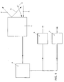
- the single figure shows a block diagram of the device for carrying out the method.
- the device comprises a distance sensor system 1, an evaluation logic 2 and vehicle components 3.
- the distance sensor system 1 scans the lateral and front surroundings for objects or motor vehicles by means of an emission signal 4.
- the emission signal 4 is swiveled over a specific segment.
- the distance sensor has a matched to the emission signal 4 receiving device, the detected by objects reflected signals 5 by incident angle and time.
- the detected signals 5 are transferred to the evaluation logic 2 for further evaluation, which converts the signals 5 into speeds and associated positions of the object by means of known algorithms.
- curves are closed.
- the safety distance measurement one needs this knowledge, in order to know also with cornering surely on which motor vehicle one is really "docked". It is also possible to determine the number of curves passed through.
- the active and / or passive overtaking operations can be determined, which can also be used for active overtaking on signals of the steering.
- the recorded data are so characteristic of the particular driving situation that they can be used to deduce the driving situation, for example, the highway, country road or city traffic. For example, high speeds and / or elongated curves are a feature of highways, whereas sharp turns and slow speeds are a feature of standing traffic.
- the individual parameters can also be weighted with each other, ie the more detected motor vehicles drive eg with very high speeds, the less play curve radius, overtaking, etc., a role to safely close the driving situation highway.
- longitudinal dynamics control and tracking software can now be tuned specifically. Further embodiments of the invention can be found in the claims 2-4, 7 and 9.
- the particular advantage of the invention is that essentially can be used on existing hardware, which allows a particularly cost-effective implementation.
Landscapes
- Engineering & Computer Science (AREA)
- Radar, Positioning & Navigation (AREA)
- Remote Sensing (AREA)
- Physics & Mathematics (AREA)
- General Physics & Mathematics (AREA)
- Electromagnetism (AREA)
- Computer Networks & Wireless Communication (AREA)
- Chemical & Material Sciences (AREA)
- Combustion & Propulsion (AREA)
- Transportation (AREA)
- Mechanical Engineering (AREA)
- Traffic Control Systems (AREA)
Description
- Die Erfindung betrifft ein Verfahren zur Erfassung der Fahrsituation eines Kraftfahrzeuges.
- Zur Verbesserung des Fahrkomforts sind vielfältige Anstrengungen in unterschiedlichen Kraftfahrzeugkomponenten unternommen worden.
- So weisen z.B. moderne Kraftfahrzeuge Längsdynamikregelungen oder Getrieberegelungen mit unterschiedlichen Fahrzeugstrategien auf, um das Kraftfahrzeug optimal dem jeweiligen Verkehrsgeschehen anzupassen. Diese Regelungen sind immer als Kompromiß Autobahn - Landstraße - Stadt abgestimmt.
- Des weiteren sind Vorrichtung zur Erfassung des Abstandes umgebender Kraftfahrzeuge, insbesondere vorausfahrender Kraftfahrzeuge, bekannt, die zur Einhaltung bzw. Überprüfung der Sicherheitsabstände beispielsweise für Überholvorgänge dienen.
- Eine solche Vorrichtung ist beispielsweise aus der DE 196 14 061 bekannt, die einen Entfernungssensor zum Abtasten eines Laserstrahls in einer Breitenrichtung eines Systemfahrzeuges aufweist, um relative Positionen und relative Winkel von Objekten in einem vorderen erfaßbaren Bereich zu bestimmen, und das Gleichspurwahrscheinlichkeiten bestimmt, daß die Objekte in derselben Spur einer Straße wie das Systemfahrzeug existieren, wobei eine veränderliche Wahrscheinlichkeitsverteilung verwendet wird, die auf den Relativpositionen und den relativen Winkeln der Objekte basiert, wodurch insbesondere Probleme der Erfassung in Kurven vermieden werden. Nachteilig an den bekannten Vorrichtungen zur Erfassung des Abstandes ist, daß die Interpretation der Fahrzeugumgebung durch das System stark von den jeweiligen Fahrsituationen abhängig ist.
- Der Erfindung liegt daher das technische Problem zugrunde, ein Verfahren zur Erfassung der Fahrsituation eines Kraftfahrzeuges zu schaffen, mittels dessen fahrsituationsabhängig Fahrzeugkomponenten automatisch abstimmbar sind.
- Die Lösung des technischen Problems ergibt sich durch die Merkmale der Patentansprüche 1 und 9.
- Dabei werden mittels einer bekannten Abstandssensorik die Anzahl und die Geschwindigkeiten der das Kraftfahrzeug umgebenden Kraftfahrzeuge ermittelt und mit Referenz- oder Schwellenwerten verglichen. Die Ermittlung der Geschwindigkeiten des Gegenverkehrs ist ebenfalls möglich, da bei herkömmlichen Abstandssensoriken diese aus den Daten identifiziert und herausgefiltert werden. Viele Fahrzeuge mit einer sehr großen Geschwindigkeit lassen beispielsweise auf eine Autobahn oder eine Landstraße schließen, wobei durch die Anzahl bzw. die auftretenden Spitzengeschwindigkeiten ermittelbar ist, ob es sich um eine Landstraße oder eine Autobahn handelt. Entsprechend kann bei niedrigen Geschwindigkeiten auf Stadtverkehr geschlossen werden. Da auch der Gegenverkehr berücksichtigt wird, kann sogar bei einseitigem Stau zuverlässig die Fahrsituation ermittelt und anderen Fahrzeugkomponenten zur Feineinstellung zur Verfügung gestellt werden. Auch sich am Fahrbahnrand befindende stehende Objekte können Auskunft über die Fahrsituation geben. Aus diesem Grund werden nach einer vorteilhaften Weiterbildung diese Objekte erfaßt und bewertet.
- Weitere vorteilhafte Ausgestaltungen der Erfindung ergeben sich aus den Unteransprüchen.
- Die Erfindung wird nachfolgend anhand eines bevorzugten Ausführungsbeispieles näher erläutert. Die einzige Figur zeigt ein Blockschaltbild der Vorrichtung zur Durchführung des Verfahrens.
- Die Vorrichtung umfaßt eine Abstandssensorik 1, eine Auswertelogik 2 und Fahrzeugkomponenten 3. Die Abstandssensorik 1 tastet mittels eines Abstrahlsignales 4 die seitliche und vordere Umgebung nach Objekten bzw. Kraftfahrzeugen ab. Je nach Ausbildung der Abstandssensorik beispielsweise als Lidar-, Radar oder Ultraschallsensor wird das Abstrahlsignal 4 über ein bestimmtes Segment geschwenkt. Des weiteren weist die Abstandssensorik eine auf das Abstrahlsignal 4 abgestimmte Empfangseinrichtung auf, die von Objekten reflektierten Signale 5 nach Einfallswinkel und Laufzeit erfaßt. Die erfaßten Signale 5 werden zur weiteren Auswertung an die Auswertelogik 2 übergeben, die mittels bekannter Algorithmen die Signale 5 in Geschwindigkeiten und zugehörige Positionen des Objektes umrechnet. Des weiteren kann mittels der erfaßten relativen Positionen bzw. Winkeln bzw. durch Auswertung der für eine Fahrschlauchprädikation verwendeten Kurvensignale auf den Radius der von erfaßten Kraftfahrzeugen durchfahrenden Kurven geschlossen werden. Bei der Sicherheitsabstandsmessung benötigt man diese Kenntnis, um auch bei Kurvenfahrten sicher zu wissen, an welchem Kraftfahrzeug man wirklich "angedockt" ist. Es kann auch die Anzahl der durchfahrenen Kurven ermittelt werden. Zusätzlich können auch die aktiven und/oder passiven Überholvorgänge ermittelt werden, wobei für die aktiven Überholvorgänge auch auf Signale der Lenkung zurückgegriffen werden kann. Die erfaßten Daten sind für die jeweilige Fahrsituation derart charakteristisch, daß aus ihnen auf die Fahrsituation beispielsweise Autobahn, Landstraße oder Stadtverkehr geschlossen werden kann. So sind beispielsweise hohe Geschwindigkeiten und/oder langgestreckte Kurven ein Merkmal für Autobahnen, wohingegen scharfe Kurven und langsame Geschwindigkeiten ein Merkmal des Standverkehrs ist. Die einzelnen Parameter können dabei auch miteinander gewichtet werden, d.h. je mehr erfaßte Kraftfahrzeuge z.B. mit sehr hohen Geschwindigkeiten fahren, desto weniger spielen Kurvenradius, Überholvorgänge etc., eine Rolle, um sicher auf die Fahrsituation Autobahn zu schließen. Mit der derart erfolgten Identifikation können nun beispielsweise Längsdynamikregelungen und Tracking-Software gezielt abgestimmt werden. Weitere Ausgestaltungen der Erfindung finden sich in den Ansprüchen 2-4, 7 und 9. Der besondere Vorteil der Erfindung ist, daß im wesentlichen auf bereits vorhandene Hardware zurückgegriffen werden kann, was eine besonders kostengünstige Realisierung erlaubt.
Claims (9)
- Verfahren zur Erfassung der Fahrsituation eines Kraftfahrzeuges, mittels einer Abstandssensorik (1) in Form eines Lidar- oder Radarsensors, umfassend folgende Verfahrensschritte:a) Erfassen zumindest sich bewegender, umgebender Objekte, insbesondere Kraftfahrzeuge, durch die Abstandssensorik,b) Ermitteln der Anzahl und der Geschwindigkeit der erfaßten Objekte, insbesondere von Kraftfahrzeugen, sowie deren Bewegungsrichtung undc) Vergleich der erfaßten und ermittelten Werte mit Referenz- oder Schwellwerten für Fahrsituationen.
- Verfahren nach Anspruch 1, dadurch gekennzeichnet, daß zusätzlich auch die Fahrspur der erfaßten Objekte, insbesondere von Kraftfahrzeugen, ermittelt wird.
- Verfahren nach Anspruch 1 oder 2, dadurch gekennzeichnet, daß die Anzahl der vorhandenen Fahrspuren ermittelt wird.
- Verfahren nach einem der Ansprüche 1 bis 3, dadurch gekennzeichnet, daß für eine Interpretation der Fahrzeugumgebung stehende Ziele außerhalb der Fahrspuren erfaßt und einzeln oder in ihrer Gesamtheit bewertet werden.
- Verfahren nach einem der Ansprüche 1 bis 4, dadurch gekennzeichnet, daß mittels der Daten der Abstandssensorik (1) die Anzahl der aktiven und/oder passiven Überholvorgänge ermittelt und mit zugehörigen Referenzwerten verglichen wird.
- Verfahren nach einem der Ansprüche 1 bis 5, dadurch gekennzeichnet, daß aus den erfaßten Daten der Abstandssensorik (1) die Anzahl und/oder die Radien der durchfahrenen Kurven ermittelt wird und mit zugehörigen Referenzwerten verglichen wird.
- Verfahren nach Anspruch 5 oder 6, dadurch gekennzeichnet, daß nur eine ermittelte Größe mit zugehörigen Referenzwerten verglichen wird, wobei die Referenzwerte von anderen ermittelten Größen abhängig sind.
- Verfahren nach einem der vorhergehenden Ansprüche, dadurch gekennzeichnet, daß die Fahrsituationen in Autobahn, Landstraße und Stadt unterteilt sind.
- Vorrichtung adaptiert zur Durchführung des Verfahrens nach einem der Ansprüche 1-8 zur Erfassung der Fahrsituation eines Kraftfahrzeuges, dadurch gekennzeichnet, daß die Vorrichtung eine Abstandssensorik (1), eine Vergleichsschaltung und einen Referenz- oder Schwellwertspeicher umfaßt, wobei aus den Daten der Abstandssensorik (1) Verkehrsparameter ableitbar und mit Referenz- oder Schwellwerten vergleichbar sind.
Applications Claiming Priority (2)
| Application Number | Priority Date | Filing Date | Title |
|---|---|---|---|
| DE19730675 | 1997-07-17 | ||
| DE19730675 | 1997-07-17 |
Publications (3)
| Publication Number | Publication Date |
|---|---|
| EP0892281A2 EP0892281A2 (de) | 1999-01-20 |
| EP0892281A3 EP0892281A3 (de) | 1999-06-30 |
| EP0892281B1 true EP0892281B1 (de) | 2006-09-20 |
Family
ID=7836020
Family Applications (1)
| Application Number | Title | Priority Date | Filing Date |
|---|---|---|---|
| EP98110908A Expired - Lifetime EP0892281B1 (de) | 1997-07-17 | 1998-06-15 | Verfahren und Vorrichtung zur Erfassung der Fahrsituation eines Kraftfahrzeuges |
Country Status (4)
| Country | Link |
|---|---|
| EP (1) | EP0892281B1 (de) |
| JP (1) | JPH1186186A (de) |
| DE (1) | DE59813731D1 (de) |
| ES (1) | ES2270483T3 (de) |
Families Citing this family (5)
| Publication number | Priority date | Publication date | Assignee | Title |
|---|---|---|---|---|
| FR2789732B1 (fr) * | 1999-02-12 | 2001-03-23 | Renault | Procede et dispositif de commande du groupe motopropulseur d'un vehicule automobile |
| FR2815130B1 (fr) * | 2000-10-06 | 2003-01-17 | Renault | Procede de regulation de distance et de vitesse d'un vehicule automobile |
| EP1195283A1 (de) * | 2000-10-06 | 2002-04-10 | Renault | Geschwindigkeits- und Abstandsregelung an einem Kraftfahrzeug |
| GB0321560D0 (en) * | 2003-09-15 | 2003-10-15 | Trw Ltd | Target detection apparatus for vehicles |
| DE102005005970A1 (de) * | 2005-02-10 | 2006-08-24 | Robert Bosch Gmbh | Fahrerassistenzystem mit Vorrichtung zur Erkennung von Sondersituationen |
Family Cites Families (10)
| Publication number | Priority date | Publication date | Assignee | Title |
|---|---|---|---|---|
| US3725921A (en) * | 1970-11-04 | 1973-04-03 | Bendix Corp | Traffic responsive speed control system |
| US4862854A (en) * | 1987-04-06 | 1989-09-05 | Mazda Motor Corporation | Control systems for vehicle engines |
| JPH0686188B2 (ja) * | 1989-04-04 | 1994-11-02 | 株式会社ユニシアジェックス | 運転状態認識装置及びこれを用いた自動変速機の変速制御装置 |
| JP3148776B2 (ja) * | 1992-08-17 | 2001-03-26 | マツダ株式会社 | 車両用道路検知装置 |
| JP3079881B2 (ja) * | 1993-08-10 | 2000-08-21 | 三菱自動車工業株式会社 | 道路交通状況推定方法および車両運転特性制御方法 |
| JPH08167099A (ja) * | 1994-12-13 | 1996-06-25 | Calsonic Corp | 光学式測定装置および光学式測定方法 |
| GB9425096D0 (en) * | 1994-12-13 | 1995-02-08 | Lucas Ind Plc | Apparatus and method for cruise control |
| JP3324325B2 (ja) * | 1995-03-14 | 2002-09-17 | 三菱電機株式会社 | 車両前方監視装置 |
| JPH0981734A (ja) * | 1995-09-08 | 1997-03-28 | Mitsubishi Electric Corp | 画像処理装置 |
| JPH09178849A (ja) * | 1995-12-25 | 1997-07-11 | Toyota Motor Corp | 車載レーダ装置 |
-
1998
- 1998-06-15 DE DE59813731T patent/DE59813731D1/de not_active Expired - Lifetime
- 1998-06-15 ES ES98110908T patent/ES2270483T3/es not_active Expired - Lifetime
- 1998-06-15 EP EP98110908A patent/EP0892281B1/de not_active Expired - Lifetime
- 1998-07-15 JP JP10200516A patent/JPH1186186A/ja active Pending
Also Published As
| Publication number | Publication date |
|---|---|
| ES2270483T3 (es) | 2007-04-01 |
| JPH1186186A (ja) | 1999-03-30 |
| EP0892281A2 (de) | 1999-01-20 |
| EP0892281A3 (de) | 1999-06-30 |
| DE59813731D1 (de) | 2006-11-02 |
Similar Documents
| Publication | Publication Date | Title |
|---|---|---|
| EP2673760B1 (de) | Verfahren zur unterstützung eines fahrers eines kraftfahrzeugs | |
| EP1052143B1 (de) | Leithilfe bei einem Fahrspurwechsel eines Kraftfahrzeuges | |
| EP1388017B1 (de) | Verfahren zur erkennung eines spurwechsels eines fahrzeugs | |
| DE102011082126B4 (de) | Sicherheitseinrichtung für kraftfahrzeuge | |
| EP2583263B1 (de) | Verfahren zur fusion eines verkehrszeichenerkennungssystems und eines spurerkennungssystems eines kraftfahrzeugs | |
| WO2008113637A1 (de) | Kollisionswarnvorrichtung für kraftfahrzeuge | |
| WO2015032707A1 (de) | Verfahren und steuer- und erfassungseinrichtung zum plausibilisieren einer falschfahrt eines kraftfahrzeugs | |
| DE102011104740A1 (de) | Verfahren und Vorrichtung zur Totwinkelüberwachung für ein Fahrzeug | |
| DE3222263A1 (de) | Abstands-warnsystem fuer kraftfahrzeuge | |
| DE102019205802A1 (de) | Verfahren zum Betreiben eines Fahrassistenzsystems und Fahrassistenzsystem | |
| WO2017220174A1 (de) | Verfahren zum ermitteln einer notbremssituation eines fahrzeuges sowie vorrichtung zur durchführung des verfahrens | |
| WO2017144381A1 (de) | Vorrichtung zur querführungsunterstützung für ein strassengebundenes fahrzeug | |
| DE102020212306A1 (de) | Verfahren zur Tunnelfrüherkennung | |
| DE19851434B4 (de) | Verfahren und Vorrichtung zur Fahrerassistenz beim Abbiegen eines Kraftfahrzeuges | |
| EP1276627B1 (de) | Verfahren zur regelung der geschwindigkeit eines fahrzeugs | |
| DE102004028404A1 (de) | Verfahren zur Schätzung des Verlaufs einer Fahrspur eines Kraftfahrzeuges | |
| EP1308751A2 (de) | Verfahren zum Betreiben eines Nahbereichserkennungssystems und Nahbereichserkennungssystem | |
| DE102008014689A1 (de) | Fahrerassistenzsystem | |
| WO2007051835A1 (de) | Verfahren zum unterstützen eines fahrers beim fahren mit einem fahrzeug | |
| EP2176837B1 (de) | Übermittlungsvorrichtung und verfahren zum übermitteln einer aktuellen position eines fahrzeugs an eine auswertezentrale | |
| EP1422586B1 (de) | Verfahren und Vorrichtung zur Überwachung eines Kraftfahrers unter Verwendung einer Fahrspurerkennung | |
| EP0892281B1 (de) | Verfahren und Vorrichtung zur Erfassung der Fahrsituation eines Kraftfahrzeuges | |
| DE10059891A1 (de) | Kraftfahrzeugabstandssensor | |
| EP1185883A1 (de) | Modellgestützte fahrspurzuordnung für fahrzeuge | |
| DE102005007800A1 (de) | Verfahren zur Erkennung eines bevorstehenden Überholvorgangs |
Legal Events
| Date | Code | Title | Description |
|---|---|---|---|
| PUAI | Public reference made under article 153(3) epc to a published international application that has entered the european phase |
Free format text: ORIGINAL CODE: 0009012 |
|
| AK | Designated contracting states |
Kind code of ref document: A2 Designated state(s): DE ES FR GB IT SE |
|
| AX | Request for extension of the european patent |
Free format text: AL;LT;LV;MK;RO;SI |
|
| PUAL | Search report despatched |
Free format text: ORIGINAL CODE: 0009013 |
|
| AK | Designated contracting states |
Kind code of ref document: A3 Designated state(s): AT BE CH CY DE DK ES FI FR GB GR IE IT LI LU MC NL PT SE |
|
| AX | Request for extension of the european patent |
Free format text: AL;LT;LV;MK;RO;SI |
|
| 17P | Request for examination filed |
Effective date: 19991230 |
|
| AKX | Designation fees paid |
Free format text: DE ES FR GB IT SE |
|
| GRAP | Despatch of communication of intention to grant a patent |
Free format text: ORIGINAL CODE: EPIDOSNIGR1 |
|
| GRAS | Grant fee paid |
Free format text: ORIGINAL CODE: EPIDOSNIGR3 |
|
| GRAA | (expected) grant |
Free format text: ORIGINAL CODE: 0009210 |
|
| AK | Designated contracting states |
Kind code of ref document: B1 Designated state(s): DE ES FR GB IT SE |
|
| PG25 | Lapsed in a contracting state [announced via postgrant information from national office to epo] |
Ref country code: IT Free format text: LAPSE BECAUSE OF FAILURE TO SUBMIT A TRANSLATION OF THE DESCRIPTION OR TO PAY THE FEE WITHIN THE PRESCRIBED TIME-LIMIT;WARNING: LAPSES OF ITALIAN PATENTS WITH EFFECTIVE DATE BEFORE 2007 MAY HAVE OCCURRED AT ANY TIME BEFORE 2007. THE CORRECT EFFECTIVE DATE MAY BE DIFFERENT FROM THE ONE RECORDED. Effective date: 20060920 |
|
| REG | Reference to a national code |
Ref country code: GB Ref legal event code: FG4D Free format text: NOT ENGLISH |
|
| REF | Corresponds to: |
Ref document number: 59813731 Country of ref document: DE Date of ref document: 20061102 Kind code of ref document: P |
|
| PG25 | Lapsed in a contracting state [announced via postgrant information from national office to epo] |
Ref country code: SE Free format text: LAPSE BECAUSE OF FAILURE TO SUBMIT A TRANSLATION OF THE DESCRIPTION OR TO PAY THE FEE WITHIN THE PRESCRIBED TIME-LIMIT Effective date: 20061220 |
|
| GBT | Gb: translation of ep patent filed (gb section 77(6)(a)/1977) |
Effective date: 20061227 |
|
| REG | Reference to a national code |
Ref country code: ES Ref legal event code: FG2A Ref document number: 2270483 Country of ref document: ES Kind code of ref document: T3 |
|
| ET | Fr: translation filed | ||
| PLBE | No opposition filed within time limit |
Free format text: ORIGINAL CODE: 0009261 |
|
| STAA | Information on the status of an ep patent application or granted ep patent |
Free format text: STATUS: NO OPPOSITION FILED WITHIN TIME LIMIT |
|
| 26N | No opposition filed |
Effective date: 20070621 |
|
| PGFP | Annual fee paid to national office [announced via postgrant information from national office to epo] |
Ref country code: GB Payment date: 20140630 Year of fee payment: 17 |
|
| PGFP | Annual fee paid to national office [announced via postgrant information from national office to epo] |
Ref country code: IT Payment date: 20140627 Year of fee payment: 17 |
|
| PGFP | Annual fee paid to national office [announced via postgrant information from national office to epo] |
Ref country code: FR Payment date: 20140630 Year of fee payment: 17 Ref country code: ES Payment date: 20140724 Year of fee payment: 17 |
|
| PG25 | Lapsed in a contracting state [announced via postgrant information from national office to epo] |
Ref country code: IT Free format text: LAPSE BECAUSE OF NON-PAYMENT OF DUE FEES Effective date: 20150615 |
|
| GBPC | Gb: european patent ceased through non-payment of renewal fee |
Effective date: 20150615 |
|
| REG | Reference to a national code |
Ref country code: FR Ref legal event code: ST Effective date: 20160229 |
|
| PG25 | Lapsed in a contracting state [announced via postgrant information from national office to epo] |
Ref country code: GB Free format text: LAPSE BECAUSE OF NON-PAYMENT OF DUE FEES Effective date: 20150615 |
|
| PG25 | Lapsed in a contracting state [announced via postgrant information from national office to epo] |
Ref country code: FR Free format text: LAPSE BECAUSE OF NON-PAYMENT OF DUE FEES Effective date: 20150630 |
|
| REG | Reference to a national code |
Ref country code: ES Ref legal event code: FD2A Effective date: 20160729 |
|
| PG25 | Lapsed in a contracting state [announced via postgrant information from national office to epo] |
Ref country code: ES Free format text: LAPSE BECAUSE OF NON-PAYMENT OF DUE FEES Effective date: 20150616 |
|
| PGFP | Annual fee paid to national office [announced via postgrant information from national office to epo] |
Ref country code: DE Payment date: 20170630 Year of fee payment: 20 |
|
| REG | Reference to a national code |
Ref country code: DE Ref legal event code: R071 Ref document number: 59813731 Country of ref document: DE |
|
| P01 | Opt-out of the competence of the unified patent court (upc) registered |
Free format text: CASE NUMBER: UPC_APP_327675/2023 Effective date: 20230523 |