EP0892282A2 - Object sensing apparatus - Google Patents
Object sensing apparatus Download PDFInfo
- Publication number
- EP0892282A2 EP0892282A2 EP98113106A EP98113106A EP0892282A2 EP 0892282 A2 EP0892282 A2 EP 0892282A2 EP 98113106 A EP98113106 A EP 98113106A EP 98113106 A EP98113106 A EP 98113106A EP 0892282 A2 EP0892282 A2 EP 0892282A2
- Authority
- EP
- European Patent Office
- Prior art keywords
- light
- filter member
- measuring device
- light receiving
- distance measuring
- Prior art date
- Legal status (The legal status is an assumption and is not a legal conclusion. Google has not performed a legal analysis and makes no representation as to the accuracy of the status listed.)
- Withdrawn
Links
- 238000005259 measurement Methods 0.000 claims abstract description 26
- 230000000694 effects Effects 0.000 description 12
- 238000013459 approach Methods 0.000 description 4
- 230000003287 optical effect Effects 0.000 description 3
- 241000287107 Passer Species 0.000 description 2
- 238000009434 installation Methods 0.000 description 2
- 239000000758 substrate Substances 0.000 description 2
- 238000005452 bending Methods 0.000 description 1
- 230000007423 decrease Effects 0.000 description 1
- 230000001419 dependent effect Effects 0.000 description 1
- 239000000428 dust Substances 0.000 description 1
- 230000002093 peripheral effect Effects 0.000 description 1
Images


Classifications
-
- G—PHYSICS
- G01—MEASURING; TESTING
- G01S—RADIO DIRECTION-FINDING; RADIO NAVIGATION; DETERMINING DISTANCE OR VELOCITY BY USE OF RADIO WAVES; LOCATING OR PRESENCE-DETECTING BY USE OF THE REFLECTION OR RERADIATION OF RADIO WAVES; ANALOGOUS ARRANGEMENTS USING OTHER WAVES
- G01S17/00—Systems using the reflection or reradiation of electromagnetic waves other than radio waves, e.g. lidar systems
- G01S17/02—Systems using the reflection of electromagnetic waves other than radio waves
- G01S17/06—Systems determining position data of a target
- G01S17/46—Indirect determination of position data
- G01S17/48—Active triangulation systems, i.e. using the transmission and reflection of electromagnetic waves other than radio waves
-
- G—PHYSICS
- G01—MEASURING; TESTING
- G01S—RADIO DIRECTION-FINDING; RADIO NAVIGATION; DETERMINING DISTANCE OR VELOCITY BY USE OF RADIO WAVES; LOCATING OR PRESENCE-DETECTING BY USE OF THE REFLECTION OR RERADIATION OF RADIO WAVES; ANALOGOUS ARRANGEMENTS USING OTHER WAVES
- G01S7/00—Details of systems according to groups G01S13/00, G01S15/00, G01S17/00
- G01S7/48—Details of systems according to groups G01S13/00, G01S15/00, G01S17/00 of systems according to group G01S17/00
- G01S7/481—Constructional features, e.g. arrangements of optical elements
Definitions
- the present invention relates to an object sensing apparatus for accurately sensing an object, such as a human body or the like, approaching an automatic door or the like.
- Distance measurement based on the principle of triangulation is well known.
- Light is projected from a light emitting element such as an infrared-ray diode through a projecting lens toward an object to which the distance is to be measured.
- Reflected light from the object is received by a light receiving element such as a PSD (position sensitive detector) placed behind a light receiving lens and at a predetermined distance, the so-called base line length, from the light emitting element.
- the distance is obtained from a position signal of the PSD.
- distance measurable range The range of distances that can be measured by a distance measuring device of this kind (referred to as “distance measurable range” hereinafter) is indicated by Z in Fig. 7.
- distance measurable range the distance to objects within a “dead zone”, i.e., the region between the right-hand end of arrow Z and the distance measuring device a .
- distance measuring device a When distance measuring device a is installed at a location retracted by a distance c from the front surface b of an installation site, a cavity or space d is created in front of the distance measuring device a . With this structure, when c is long enough, the front surface b is outside of the dead zone.
- the range to the left of the front surface b where there is a possibility that someone approaches is within the distance measurable range.
- the distance measuring apparatus a is installed at such a retracted location, dust or the like tends accumulate within the space in front of the device a or in the vicinity of a front opening at the front surface b .
- a protection cover, a filter or the like hereinafter referred to as a filter member
- a filter member e is provided at some spacing c to and in parallel with the distance measuring device a .
- Light La emitted by a light emitting element f passes through a light projecting lens g and is projected toward an object T .
- Light Lb reflected by the object T is transmitted through a light receiving lens h and impinges on a light receiving element i .
- Part of the light La is scattered by the inner surface of filter member e , causing scattered light Lc .
- reflected light Le or scattered light Lf is similarly created at the inner surface of filter member e .
- These light components pass through light receiving lens h and arrive at light receiving element i , as various conditions may be. This extra reflected light or scattered light, when arriving at light receiving element i , causes an error in the measurement result and makes accurate distance measurement impossible.
- Light reflection at the inner surface of filter member e is explained in more detail with reference to Fig. 8(a).
- Light emitting element f is usually arranged at some distance behind the focal plane F of light projecting lens g so that an image thereof is focused at a point having a predetermined distance from light emitting lens g .
- the light passing through light projecting lens g includes light beams from secondary light sources such light reflected by a substrate mounting light emitting element f , a stem and a case surface, in addition to direct light from light emitting element f . If an outer peripheral point P of the light emitting element or the substrate is taken as an example, this point P is focused at Pa due to light Ld , Lg transmitted through light projecting lens g .
- the filter member e1 is at a location closer to light projecting lens g than that of the filter member e
- the filter member e2 is at a location more distant from light projecting lens g than that of filter member e .
- scattered light from the reflecting surface is considered negligible and excluded from the study.
- the light caused by reflection of the light Ld and light Lg at the inner surface of filter members e1 , e and e2 are respectively Le1 , Le , Le2 and Lh1 , Lh , Lh2 .
- Reflected light Le1 and Lh1 does not pass through light receiving lens h and does not arrive at light receiving element i and, therefore, has no effect upon the measurement result.
- reflected light beams Le and Lh both pass through light receiving lens h and arrive at light receiving element i and have, thus, an effect upon a measurement result.
- Reflected light Le2 does not pass through light receiving lens h and does not arrive at light receiving element i . However, reflected light Lh2 passes through light receiving lens h and arrives at light receiving element i . In this case also, the measurement result is affected.
- the degree of influence depends upon various conditions such as the aperture of the light projecting/receiving lens, base line length (distance between the light projecting and receiving lenses), size of the light emitting element, location of the light emitting element (distance from the lens), magnitude of secondary light, condition of reflecting surface of the filter member (magnitude and direction of diffusing reflection due to difference in smoothness), size and arrangement of the light receiving element, and so on, besides location of the reflecting surface.
- the effect or influence is depicted as a graph in Fig. 8(b) in which the degree of influence E on the distance measurement result is plotted on the ordinate and the distance between the light projecting lens and the filter member is plotted on the abscissa.
- the location of filter member e1 is within the dead zone within which distances cannot be measured by the distance measuring device a. Thus, if this location is selected either can the filter member not be positioned near to the front surface b of the cavity in front of the device a , or the length c of the cavity has to be made shorter. This latter possibility undesirably results in part of the dead zone extending in front of the installation site so that an object very near to the object sensing apparatus could possibly not be detected. On the other hand, the location of filter member e2 or an even greater spacing requires the length of the cavity in front of the device a to be increased which is also undesirable.
- the filter member is inclined with an angle of inclination such that light reflected or scattered by the inner surface of the filter member is reflected in a direction different from a direction toward said light receiving means.
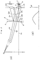
- FIG. 1 showing a horizontal cross-sectional view.
- a distance measuring device 1 is accommodated in and attached to an attaching member 2 of an object sensing apparatus.
- the attaching member 2 has a depth substantially greater than that of the distance measuring device 1.
- a cavity 2b exists between the front surface 2a of the attaching member 2 and the front surface of the distance measuring device 1.
- the cavity 2b has, at its front end, an opening 2c in which is arranged a filter member 3.
- This filter member 3 is at a position corresponding to the position of the filter member e explained in Fig. 8.
- the distance measuring device 1 has a light emitting element 11 and a light receiving element 12, such as a PSD, juxtaposed with a predetermined spacing and on the same plane. If viewed from the front of the apparatus, light emitting element 11 is on the right-hand side (lower side of the drawing) and light receiving element 12 is on the left-hand side (upper side of the drawing). A light projecting lens 11a is provided in front of light emitting element 11 and a light receiving lens 12a is provided in front of light receiving element 12.
- the spacing X between the line (or plane) connecting the axial centers of the lenses 11a, 12a and the center of the inner surface of the filter member 3 is chosen such that distance measuring device 1 has a distance measurable range Z beginning at a position which is closer to the device 1 than is the center of the filter member 3. Consequently, since the front surface 2a of the attaching member 2 is within the distance measurable range Z close to a boundary thereof, the distance to an object T can be accurately measured even when the object is approaching or near to the front surface 2a.
- the filter member 3 is inclined at a predetermined angle ⁇ so that components of the light emitted from light emitting element 11 which are reflected or scattered at the inner surface 3a of filter member 3 are given a direction in which they do not reach the light receiving element. That is, in this embodiment, the filter member 3 is inclined at the angle ⁇ with respect to a plane perpendicular to the light projecting axis along which the light La emitted from the light emitting element 11 propagates. Filter member 3 is inclined in such a way that the spacing between the axial center plane of the lenses 11a, 12a and the inner surface of the filter member on the optical axis of light receiving lens 12a is shorter than the corresponding spacing on the optical axis of light projecting lens 11a.
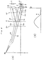
- Fig. 2(b) shows a graph qualitatively illustrating the relationship between the required angle of inclination ⁇ , plotted on the ordinate, and the spacing between filter member 3 and device 1, plotted on the abscissa. If filter member 3 is placed at a position near measuring device 1, there is no necessity of inclining the filter member. However, as the filter member is shifted away from the distance measuring device 1, the necessary angle ⁇ gradually increases, reaches a maximum at a certain position and decreases again as the spacing between the filter member and the distance measuring device 1 is further increased.
- an angle ⁇ 18° is appropriate.
- Fig. 3 shows a horizontal cross-sectional view of a second embodiment.
- a filter member 23 is used instead of filter member 3 of the first embodiment.
- Filter member 23 has two portions, a portion 23c on the left-hand side (upper side in the drawing) of a central portion 23b and a portion 23d on the right-hand side (lower side in the drawing) of central portion 23b. The two portions are bent with respect to one another at central portion 23b.
- Portion 23c opposite to light receiving lens 12a is substantially perpendicular to the light projecting axis of the light emitting element 11.
- portion 23d opposite to the light projecting lens 11a is inclined by a predetermined angle ⁇ with respect to a plane perpendicular to the light projecting axis.
- Portion 23d is a portion where the spot formed by the light beam emitted from light emitting element 11 includes a spot area 23e within which the brightness equals or exceeds a predetermined value.
- This predetermined value represents a brightness that, if the light were reflected at the inner surface 23a of filter member 23 and would reach the light receiving element 12, it would have a noticeable effect upon the measurement result, whereas such effect of light having a brightness below the predetermined value would be negligible.
- portion 23d is inclined by angle ⁇ , if the spacing from the axial center plane of the lenses 11a, 12a to the central portion 23b of filter member 23 is X , the distance between that plane and the right-hand end of filter member 23 is X + ⁇ as shown in Fig. 3.
- Fig. 4 shows a third embodiment which differs from the second embodiment only by use of a filter member 33 instead of filter member 23. Only filter member 33 is shown in Fig. 4. Like filter member 23 of the second embodiment filter member 33 has a left-hand portion 33c, a central portion 33b and a right-hand portion 33d. Portion 33c corresponds to and is arranged in the same way as portion 23c of filter member 23. Portion 33d is inclined at an angle ⁇ in a similar way as portion 23d of filter member 23.
- filter member 33 of this embodiment is once bent towards the distance measuring device 1 by such a distance that the left- and right-hand ends of the filter member are substantially in the same plane perpendicular to the light projecting axis, despite the fact that portion 33d is inclined. Therefore, also in this embodiment a spot area 33e corresponding to the spot area 23e of the second embodiment is inclined with the same result as that explained for the second embodiment.
- Fig. 5 shows a vertical cross-sectional view of a fourth embodiment.
- a filter member 43 is inclined vertically by an angle ⁇ with respect to a plane perpendicular to the light projecting axis and in a direction such that its upper portion is nearer to the distance measuring device 1 than the lower portion. It is to be noted that that filter member 43 could as well be inclined in the opposite direction, i.e., such that its lower portion is nearer to the distance measuring device 1 than the upper portion.
- Fig. 6 shows a fifth embodiment.
- Fig. 6(a) shows a vertical cross-sectional view of the fifth embodiment.
- a filter member 53 as shown in the perspective view in Fig. 6(b), has a boundary central portion 53b, a left-hand portion 53c opposite to the light receiving lens (not shown) and a right-hand portion 53d opposite to light projecting lens 11a.
- Portion 53d is perpendicular to the light projecting axis without inclination.
- Portion 53d including the spot area 53e is inclined vertically by an angle ⁇ similar to filter member 43 in Fig. 5.
- the upper part of portion 53d may be inclined either towards or away from the distance measuring device 1.
- the spot area is inclined so that light reflected (or scattered) at the inner surface of the filter member is turned either downward or upward so that it cannot impinge on the light receiving element of the distance measuring device 1.
- an error in the measurement result is prevented in the same way as in the preceding embodiments.
Landscapes
- Physics & Mathematics (AREA)
- Engineering & Computer Science (AREA)
- Electromagnetism (AREA)
- Computer Networks & Wireless Communication (AREA)
- General Physics & Mathematics (AREA)
- Radar, Positioning & Navigation (AREA)
- Remote Sensing (AREA)
- Measurement Of Optical Distance (AREA)
- Length Measuring Devices By Optical Means (AREA)
- Photometry And Measurement Of Optical Pulse Characteristics (AREA)
- Geophysics And Detection Of Objects (AREA)
- Optical Radar Systems And Details Thereof (AREA)
Abstract
Description
Claims (5)
- An object sensing apparatus, comprising:a distance measuring device (1) having light projecting means (11, 11a) for projecting a measurement light beam toward an object (T), and light receiving means (12, 12a) for receiving a reflected light beam reflected by said object, anda filter member (3; 23; 33; 43; 53) provided in front of said distance measuring device (1) with a predetermined spacing in between,
characterized in that at least a portion (3d; 23d; 33d; 53d) of said filter member is provided at an angle of inclination () such that components of the measurement light beam reflected or scattered by an inner surface of said filter member are given a direction different from a direction toward said light receiving means. - The apparatus according to claim 1, wherein a portion (23d; 33d; 53d) of said filter member (23; 33; 53) is inclined at said angle of inclination () with respect to a plane perpendicular to a light projecting axis of said light projecting means (11, 11a), said portion including a spot area (23e; 33e; 53e) within which the brightness of said measurement light beam equals or exceeds a predetermined value.
- The apparatus according to claim 1 or 2, wherein said light projecting means (11, 11a) and said light receiving means (12, 12a) are juxtaposed in a left-right direction on the same plane, and said filter member (3) or said portion (23d; 33d) of it is inclined in said left-right direction with respect to a plane perpendicular to a light projecting axis of said light projecting means such that it is nearer to said light receiving means than to said light projecting means.
- The apparatus according to claim 1 or 2, wherein said light projecting means (11, 11a) and said light receiving means (12, 12a) are juxtaposed in a left-right direction on the same plane, and said filter member (43) or said portion (53d) of it is inclined in an up-down direction with respect to a plane perpendicular to a light projecting axis of said light projecting means.
- The apparatus according to any one of claims 1 to 4, wherein said filter member is provided within a distance measurable range (Z) of said distance measuring device (1) and in the vicinity of a boundary thereof.
Applications Claiming Priority (3)
| Application Number | Priority Date | Filing Date | Title |
|---|---|---|---|
| JP18984297 | 1997-07-15 | ||
| JP9189842A JPH1137714A (en) | 1997-07-15 | 1997-07-15 | Object detector |
| JP189842/97 | 1997-07-15 |
Publications (2)
| Publication Number | Publication Date |
|---|---|
| EP0892282A2 true EP0892282A2 (en) | 1999-01-20 |
| EP0892282A3 EP0892282A3 (en) | 1999-06-16 |
Family
ID=16248126
Family Applications (1)
| Application Number | Title | Priority Date | Filing Date |
|---|---|---|---|
| EP98113106A Withdrawn EP0892282A3 (en) | 1997-07-15 | 1998-07-14 | Object sensing apparatus |
Country Status (3)
| Country | Link |
|---|---|
| US (1) | US6100983A (en) |
| EP (1) | EP0892282A3 (en) |
| JP (1) | JPH1137714A (en) |
Cited By (1)
| Publication number | Priority date | Publication date | Assignee | Title |
|---|---|---|---|---|
| CN104634313A (en) * | 2015-02-04 | 2015-05-20 | 金华马卡科技有限公司 | Distance measurement instrument |
Families Citing this family (2)
| Publication number | Priority date | Publication date | Assignee | Title |
|---|---|---|---|---|
| JP5721069B2 (en) * | 2010-12-10 | 2015-05-20 | 国立大学法人 千葉大学 | LED rider device |
| CN114080546A (en) * | 2019-08-16 | 2022-02-22 | 索尼半导体解决方案公司 | Protective cover and light emitting device |
Family Cites Families (6)
| Publication number | Priority date | Publication date | Assignee | Title |
|---|---|---|---|---|
| US3214596A (en) * | 1962-10-31 | 1965-10-26 | Machinery Electrification Inc | Photoelectric sensor structure including light source and inclined lens |
| JPS61269087A (en) * | 1985-05-23 | 1986-11-28 | Toshiba Corp | Light wave level meter |
| GB2206690B (en) * | 1987-06-30 | 1991-12-11 | Matsushita Electric Works Ltd | Optically scanning displacement sensor |
| US5220453A (en) * | 1991-02-20 | 1993-06-15 | Luxtec Corporation | Telescopic spectacles with coaxial illumination |
| US5455669A (en) * | 1992-12-08 | 1995-10-03 | Erwin Sick Gmbh Optik-Elektronik | Laser range finding apparatus |
| US5602376A (en) * | 1993-05-07 | 1997-02-11 | Psc Inc. | Hand-mounted optical scanner system |
-
1997
- 1997-07-15 JP JP9189842A patent/JPH1137714A/en not_active Abandoned
-
1998
- 1998-07-14 EP EP98113106A patent/EP0892282A3/en not_active Withdrawn
- 1998-07-15 US US09/116,320 patent/US6100983A/en not_active Expired - Fee Related
Cited By (2)
| Publication number | Priority date | Publication date | Assignee | Title |
|---|---|---|---|---|
| CN104634313A (en) * | 2015-02-04 | 2015-05-20 | 金华马卡科技有限公司 | Distance measurement instrument |
| CN104634313B (en) * | 2015-02-04 | 2018-12-18 | 金华马卡科技有限公司 | A kind of rangefinder |
Also Published As
| Publication number | Publication date |
|---|---|
| EP0892282A3 (en) | 1999-06-16 |
| US6100983A (en) | 2000-08-08 |
| JPH1137714A (en) | 1999-02-12 |
Similar Documents
| Publication | Publication Date | Title |
|---|---|---|
| US8878901B2 (en) | Time of flight camera unit and optical surveillance system | |
| US20030227635A1 (en) | Device and method for the optical detection of objects | |
| JPH0815413A (en) | Distance measuring device | |
| EP0768542B1 (en) | Optical distance measuring apparatus | |
| JP6993420B2 (en) | Rider sensor that detects objects | |
| JP6903145B2 (en) | Rider sensor for detecting objects | |
| US20170139039A1 (en) | Optoelectronic Sensor and Method for Detecting an Object | |
| US5111056A (en) | Optical measurement system determination of an object profile | |
| JP2589278Y2 (en) | Apparatus for detecting an object in sheet form | |
| JP2016090584A (en) | Sensor | |
| JPH11257917A (en) | Reflective optical sensor | |
| JP2005017382A (en) | Ranging sensor and electronic device equipped with the same | |
| JP2007514942A (en) | Distance measurement device for distant and close objects | |
| US20050184225A1 (en) | Light barrier or light grid with alignment mechanism | |
| US12000961B2 (en) | Lidar device | |
| KR100568439B1 (en) | Ellipsometer Measuring Device | |
| US20070035954A1 (en) | Device for detecting the dirt accumulation on a transparent covering pane in front of a optical unit | |
| EP0892282A2 (en) | Object sensing apparatus | |
| JP2011141142A (en) | Range finder and electronic equipment | |
| JP4127579B2 (en) | Light wave distance meter | |
| JPH10332321A (en) | Photoelectronic sensor | |
| EP0654690B1 (en) | Active-type automatic focusing apparatus | |
| US20220244397A1 (en) | Lidar system having a ray optics diagnosis | |
| JP2007031103A (en) | Elevator passenger detection device | |
| JP4143759B2 (en) | Optical coordinate input device |
Legal Events
| Date | Code | Title | Description |
|---|---|---|---|
| PUAI | Public reference made under article 153(3) epc to a published international application that has entered the european phase |
Free format text: ORIGINAL CODE: 0009012 |
|
| AK | Designated contracting states |
Kind code of ref document: A2 Designated state(s): DE FR GB |
|
| AX | Request for extension of the european patent |
Free format text: AL;LT;LV;MK;RO;SI |
|
| PUAL | Search report despatched |
Free format text: ORIGINAL CODE: 0009013 |
|
| AK | Designated contracting states |
Kind code of ref document: A3 Designated state(s): AT BE CH CY DE DK ES FI FR GB GR IE IT LI LU MC NL PT SE |
|
| AX | Request for extension of the european patent |
Free format text: AL;LT;LV;MK;RO;SI |
|
| RIC1 | Information provided on ipc code assigned before grant |
Free format text: 6G 01S 17/46 A, 6G 01S 7/481 B |
|
| 17P | Request for examination filed |
Effective date: 19991124 |
|
| AKX | Designation fees paid |
Free format text: DE FR GB |
|
| 17Q | First examination report despatched |
Effective date: 20040604 |
|
| STAA | Information on the status of an ep patent application or granted ep patent |
Free format text: STATUS: THE APPLICATION IS DEEMED TO BE WITHDRAWN |
|
| 18D | Application deemed to be withdrawn |
Effective date: 20041015 |