EP0892294A2 - A device for optical connection of an optical fibre, with another optical element - Google Patents
A device for optical connection of an optical fibre, with another optical element Download PDFInfo
- Publication number
- EP0892294A2 EP0892294A2 EP98108031A EP98108031A EP0892294A2 EP 0892294 A2 EP0892294 A2 EP 0892294A2 EP 98108031 A EP98108031 A EP 98108031A EP 98108031 A EP98108031 A EP 98108031A EP 0892294 A2 EP0892294 A2 EP 0892294A2
- Authority
- EP
- European Patent Office
- Prior art keywords
- retainer
- end surface
- optical
- connector element
- engagement
- Prior art date
- Legal status (The legal status is an assumption and is not a legal conclusion. Google has not performed a legal analysis and makes no representation as to the accuracy of the status listed.)
- Granted
Links
- 230000003287 optical effect Effects 0.000 title claims abstract description 39
- 239000013307 optical fiber Substances 0.000 title claims abstract description 34
- 239000000835 fiber Substances 0.000 description 16
- 230000005540 biological transmission Effects 0.000 description 2
- 239000000853 adhesive Substances 0.000 description 1
- 230000001070 adhesive effect Effects 0.000 description 1
- 239000013013 elastic material Substances 0.000 description 1
- 230000035945 sensitivity Effects 0.000 description 1
Images
Classifications
-
- G—PHYSICS
- G02—OPTICS
- G02B—OPTICAL ELEMENTS, SYSTEMS OR APPARATUS
- G02B6/00—Light guides; Structural details of arrangements comprising light guides and other optical elements, e.g. couplings
- G02B6/24—Coupling light guides
- G02B6/36—Mechanical coupling means
- G02B6/3628—Mechanical coupling means for mounting fibres to supporting carriers
- G02B6/3632—Mechanical coupling means for mounting fibres to supporting carriers characterised by the cross-sectional shape of the mechanical coupling means
- G02B6/3644—Mechanical coupling means for mounting fibres to supporting carriers characterised by the cross-sectional shape of the mechanical coupling means the coupling means being through-holes or wall apertures
-
- G—PHYSICS
- G02—OPTICS
- G02B—OPTICAL ELEMENTS, SYSTEMS OR APPARATUS
- G02B6/00—Light guides; Structural details of arrangements comprising light guides and other optical elements, e.g. couplings
- G02B6/24—Coupling light guides
- G02B6/26—Optical coupling means
- G02B6/32—Optical coupling means having lens focusing means positioned between opposed fibre ends
-
- G—PHYSICS
- G02—OPTICS
- G02B—OPTICAL ELEMENTS, SYSTEMS OR APPARATUS
- G02B6/00—Light guides; Structural details of arrangements comprising light guides and other optical elements, e.g. couplings
- G02B6/24—Coupling light guides
- G02B6/42—Coupling light guides with opto-electronic elements
- G02B6/4201—Packages, e.g. shape, construction, internal or external details
- G02B6/4204—Packages, e.g. shape, construction, internal or external details the coupling comprising intermediate optical elements, e.g. lenses, holograms
Definitions
- the present invention relates to a device for optical connection of an optical fibre with another optical element, for example a lens.
- optical connections between the different optical elements included in the system.
- optical connections between different lengths of optical fibres, between an optical fibre and a light source, for example a diode, between an optical fibre and a light detector etc.
- a light source for example a diode
- Each connection must be established while using very great accuracy if the losses shall be kept at a minimum.
- the problem of providing a correct connection is emphasized by the fact that optical fibres have a very small cross sectional area and that also small deviations from a correct position between two fibre end portions which shall be connected with each other cause substantial losses. It is important especially to avoid angular deviations between the fibres, i.e. it is important that the fibres which are connected with each other are positioned on the same optical axis.
- the optical fibres and the lenses are positioned on the same optical axis as well as that the end surfaces of the fibres are positioned in the focus of the lens in question.
- the connections between the optical fibres and the lenses constitute the most sensitive parts of the connection system while the optical connection of the lenses to each other can easily be provided without errors.
- a previously known device for optical connection of an optical fibre with another optical element comprises a substantially sleeve-shaped retainer and a connector element.
- the sleeve-shaped retainer is intended for fixing the optical fibre in a predetermined position in relation to reference surfaces formed on the retainer and including an end surface of the retainer at which the end surface of the optical fibre is intended to be positioned.
- the connector element is provided with engagement surfaces adapted to engage the reference surfaces of the retainer for defining the position of the retainer and thereby the optical fibre in relation to the device, the engagement surfaces of the retainer comprising an engagement surface adapted to engage the end surface of the retainer.
- the connector element has a surface for defining the position of the other optical element, for example the lens, in relation to the end surface of the retainer.
- the object of present invention is to provide a device of said kind, in which the determination of the position of the end surface of the retainer in relation to the engagement surfaces of the connector element and thereby in relation to the other optical element, for example the lens, presents greater accuracy than in previously known devices of said kind, so that the losses in the connection between the optical fibre and the other optical element, for example the lens, are reduced to a minimum.
- the device according to the invention is characterized in that the engagement surface of the connector element adapted to engage the end surface of the retainer is constituted by a funnel-shaped surface tapering from the end surface of the retainer.
- the funnel-shaped surface can be of conical design or can be of convex design. If the funnel-shaped surface is of conical design it is preferred that the surface has a cone angle exceeding 90° and for example has a cone angle of about 172°.
- the end surface of the retainer intended to engage the engagement surface of the connector element is preferably of spherical shape providing that the engagement between the end surface of the retainer and the funnel-shaped engagement surface of the connector element is given the shape of an annular, narrow, substantially line-shaped engagement surface.
- the end surface of the retainer engaging the engagement surface of the connector element can also be of flat design and thereby, this flat surface preferably has an outer edge portion formed with a radius, said edge portion thereby constituting the part of the end surface of the retainer, which engages the funnel-shaped surface of the connector element.
- the connector element has also a surface for defining the position of the other optical element, for example the lens, in relation to the end surface of the retainer, and this surface for defining the position of the other optical element is suitably constituted by a circular edge surface formed with a radius.
- the device according to the invention is adapted to be included a system for connecting an optical fibre with another optical fibre, in which system the optical fibres are connected with one lens each, so that the transmission of the light between the optical elements takes place through the lenses.
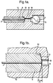
- the embodiment of a device according to the invention schematically shown in section in Fig. 1a is used for connecting an optical fibre 2 with a spherical lens 4.
- the end portion of the optical fibre 2 is enclosed in a fibre retainer 6 designed as a sleeve.
- the fibre retainer 6 is cylindrical along the main portion of its outer surface and has at its right end in the figure a spherical reference surface 8.
- the optical fibre 2 is fixed in the fibre retainer 6 in a manner known per se, for example by means of an adhesive, the end surface of the optical fibre 2 being positioned in the same plane as the spherical end surface 8 of the retainer 6.
- a correct position of the end surface of the optical fibre 2 can be provided by fixing the fibre with the end portion thereof projecting somewhat outside the spherical end surface 8, whereupon the fibre is ground to the plane of the end surface 8.
- the end surface of the fibre 2 When the end surface of the fibre 2 is positioned in the plane of the spherical end surface 8, the end surface of the fibre 2 will be related to the spherical reference surface 8 in a predetermined way.
- the device for optical connection of the optical fibre 2 with the spherical lens 4 comprises in addition to the retainer 6 a connector element 10.
- the connector element 10 is provided with surfaces for determining the relative position between the retainer 6 and thereby the optical fibre 2 and the spherical lens 4.
- the surface of the connector element 20 for defining the position of the fibre retainer 6 and thereby the optical fibre 2 is constituted by a funnel-shaped engagement surface 12 tapering in the direction from the retainer 6.
- the engagement surface 12 is of conical design having an angle a according to Fig. 1b of 3 - 4°, i.e. a cone angle of 172 - 174°.
- the surface for defining the position of the spherical lens 4 in the connector element 10 and thereby for defining the relative position between the optical fibre 2 and the spherical lens 4 is constituted by a circular edge surface 16 formed with a radius.
- the circular edge surface is formed with a radius of about 0,25 mm and provides an extremely accurate determination of the position of the spherical lens 4 without damaging the surface of the spherical lens by subjecting the surface to too great stresses.
- the fibre retainer 6 and the spherical lens 4 are maintained in firm engagement with the conical engagement surface 12 and the edge surface 16 formed with a radius, respectively, by means of arrangements not shown in detail.
- these arrangements can be constituted by a conventional nut sleeve engaging a shoulder on the fibre retainer 6, not shown in the drawing, while said arrangement in respect of the spherical lens 4 can be constituted by a threaded spigot threaded into the connector element 10 and having at its surface adapted to engage the spherical lens 4 a ring consisting of elastic material elastically forcing the spherical lens 4 against the surface 14
- the conical surface 12 and the edge surface 16 formed with a radius are positioned in relation to each other so that the optical fibre 2 and the spherical lens 4 are positioned on the same optical axis and at such an axial distance from each other that the end surface of the optical fibre 2 is in the focus of the spherical lens 4, when the spherical reference surface 8 and the spherical lens 4 engage their respective surfaces.
- the optical connection between the optical fibre 2 and the spherical lens 4 is established through a substantially cylindrical opening 18 in the connector element 10, said opening 18 extending between the end surface 8 of the retainer 6 and the spherical lens 4.
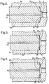
- the embodiment of the device shown in Fig. 2 comprises a retainer 6a for an optical fibre 2a.
- the retainer 6a has a spherical end surface 8a.
- the device according to Fig. 2 differs from the device according to Figs. 1a and 1b with regard to the design of the engagement surface 20 of the connector element 10a, which surface is engaged by the spherical end surface 8a of the retainer 6a.
- the engagement surface 20 is in the embodiment according to Fig. 2 tapering in a funnel-shaped way from the end surface 8a of the retainer 6a at a somewhat convex shape of said surface.
- the embodiment of the device according to the invention shown in Fig. 3 comprises a retainer 22 for the optical fibre 2b, in which the end surface 24 of the retainer 22 is of substantially flat design having an outer edge portion 26 formed with a radius. Preferably, the radius of the outer edge portion 26 is about 0,1 mm.
- the engagement surface 28 of the connector element 6b is of substantially the same design as the engagement surface 12 in the embodiment according to Figs. 1a and 1b, i.e. the engagement surface 28 is an annular, conical surface having a cone angle of 172 - 174°.
- annular, narrow, substantial line-shaped engagement surface 30 which in an extremely accurately defined way defines the position of the retainer 22 in the connector element 6b with regard to the position in the axial direction as well as the position in the radial direction.
- the retainer 22a is designed in the same way as the retainer 22 according to the embodiment of Fig. 3, i.e. the retainer has a flat end surface 24a with an outer edge portion 26a formed with a radius.
- the engagement surface 32 of the connector element 6c is in a funnel-shaped way tapering in the direction from the retainer 22a at a somewhat convex design.
- the embodiment according to Fig. 4 is an agreement with the embodiment according to Fig. 2, even if the convex surface 32 forms a somewhat greater angle with the diametrical plane than the surface 20 in the embodiment according to Fig. 2.
Landscapes
- Physics & Mathematics (AREA)
- General Physics & Mathematics (AREA)
- Optics & Photonics (AREA)
- Optical Couplings Of Light Guides (AREA)
- Mechanical Coupling Of Light Guides (AREA)
Abstract
Description
Claims (13)
- A device for optical connection of an optical fibre (2) with another optical element, for example a lens (4), comprising a substantially sleeve-shaped retainer (6) for fixing the optical fibre in a predetermined position in relation to reference surfaces on the retainer, said reference surfaces comprising an end surface (8; 24) on the retainer at which the end surface of the optical fibre is intended to be positioned, and further comprising a connector element (10) having engagement surfaces adapted to engage the reference surfaces of the retainer for defining the position of the retainer and thereby the optical fibre in relation to the device, in which the engagement surfaces of the connector element comprises an engagement surface (12; 20; 28; 32) adapted to engage the end surface (8; 24) of the retainer, characterized in that the engagement surface (12; 20; 28; 32) of the connector element (10), which is adapted to engage the end surface (8; 24) of the retainer (6) is constituted by a funnel-shaped surface tapering in the direction from the end surface of the retainer.
- A device as claimed in claim 1, characterized in that the funnel-shaped surface (12; 28) is of conical design.
- A device as claimed in claim 2, characterized in that the conical surface (12; 28) has a cone angle exceeding 90°.
- A device as claimed in claim 3, characterized in that the conical surface (12; 28) has a cone angle of about 172°.
- A device as claimed in claim 1, characterized in that the funnel-shaped surface (20; 32) is of convex shape.
- A device as claimed in any of the preceding claims, characterized in that the end surface (8; 24) of the retainer (6) engages the engagement surface (12; 20; 28; 32) of the retainer element (16) at an annular, narrow, substantially line-shaped engagement surface (14; 21; 30; 34).
- A device as claimed in claim 6, characterized in that the end surface (8) of the retainer (6), which engages the engagement surface (12; 20) of the connector element is of substantially spherical shape.
- A device as claimed in any of claims 1 - 6, characterized in that the end surface (24) of the retainer (6), which engages the engagement surface (28; 32) of the connector element is of substantially flat shape.
- A device as claimed in claim 8, characterized in that the substantially flat end surface (24) of the retainer (16) has an outer edge portion (26) formed with a radius.
- A device as claimed in any of the preceding claims, characterized in that the connector element (10) has a surface (16) for defining the position of the other optical element, for example the lens (4), in relation to the end surface (8; 24) of the retainer (6).
- A device as claimed in claim 10, in which the other optical element is constituted by a spherical lens (4), characterized in that the surface of the connector element (10) for defining the position of the spherical lens (4) in relation to the end surface (8; 24) of the retainer (6) is constituted by a circular edge surface (16) formed with a radius.
- A device as claimed in claim 11, characterized in that the circular edge surface (16) is formed with a radius having a magnitude of about 0,25 mm.
- A device as claimed in any of the preceding claims, characterized in that the connector element (10) is formed with an opening (18) extending between the end surface (8; 24) of the retainer (6) and the other optical element (4).
Priority Applications (1)
| Application Number | Priority Date | Filing Date | Title |
|---|---|---|---|
| EP02011595A EP1239313A1 (en) | 1997-07-18 | 1998-05-02 | A device for optical connection of an optical fibre with another optical element |
Applications Claiming Priority (2)
| Application Number | Priority Date | Filing Date | Title |
|---|---|---|---|
| SE9702754A SE520624C2 (en) | 1997-07-18 | 1997-07-18 | Device for optical connection of one optical fiber to another optical element |
| SE9702754 | 1997-07-18 |
Related Child Applications (1)
| Application Number | Title | Priority Date | Filing Date |
|---|---|---|---|
| EP02011595A Division EP1239313A1 (en) | 1997-07-18 | 1998-05-02 | A device for optical connection of an optical fibre with another optical element |
Publications (3)
| Publication Number | Publication Date |
|---|---|
| EP0892294A2 true EP0892294A2 (en) | 1999-01-20 |
| EP0892294A3 EP0892294A3 (en) | 2000-03-29 |
| EP0892294B1 EP0892294B1 (en) | 2002-11-06 |
Family
ID=20407785
Family Applications (2)
| Application Number | Title | Priority Date | Filing Date |
|---|---|---|---|
| EP98108031A Expired - Lifetime EP0892294B1 (en) | 1997-07-18 | 1998-05-02 | A device for optical connection of an optical fibre, with another optical element |
| EP02011595A Withdrawn EP1239313A1 (en) | 1997-07-18 | 1998-05-02 | A device for optical connection of an optical fibre with another optical element |
Family Applications After (1)
| Application Number | Title | Priority Date | Filing Date |
|---|---|---|---|
| EP02011595A Withdrawn EP1239313A1 (en) | 1997-07-18 | 1998-05-02 | A device for optical connection of an optical fibre with another optical element |
Country Status (8)
| Country | Link |
|---|---|
| US (1) | US6095696A (en) |
| EP (2) | EP0892294B1 (en) |
| AT (1) | ATE227432T1 (en) |
| AU (1) | AU727292B2 (en) |
| CA (1) | CA2239561C (en) |
| DE (1) | DE69809142T2 (en) |
| ES (1) | ES2193436T3 (en) |
| SE (1) | SE520624C2 (en) |
Cited By (2)
| Publication number | Priority date | Publication date | Assignee | Title |
|---|---|---|---|---|
| EP2770354A4 (en) * | 2011-10-18 | 2015-06-03 | Mitsubishi Pencil Co | Optically coupling member, optical connector using same, and member for holding optically coupling member |
| WO2015133958A1 (en) | 2014-03-06 | 2015-09-11 | Aktiebolaget Micropol Fiberoptic | Collimating lens |
Families Citing this family (6)
| Publication number | Priority date | Publication date | Assignee | Title |
|---|---|---|---|---|
| US7263956B2 (en) | 1999-07-01 | 2007-09-04 | Delphi Technologies, Inc. | Valve lifter assembly for selectively deactivating a cylinder |
| DE10146129A1 (en) | 2001-09-19 | 2003-04-03 | Ina Schaeffler Kg | Switching element for a valve train of an internal combustion engine |
| ATE300665T1 (en) * | 2002-02-06 | 2005-08-15 | Ina Schaeffler Kg | SWITCHING ELEMENT FOR A VALVE DRIVE OF AN INTERNAL COMBUSTION ENGINE |
| US6866014B2 (en) * | 2003-04-24 | 2005-03-15 | Delphi Technologies, Inc. | Anti-rotation guide for a deactivation hydraulic valve lifter |
| US8161929B2 (en) * | 2007-11-21 | 2012-04-24 | Schaeffler Kg | Switchable tappet |
| US8196556B2 (en) * | 2009-09-17 | 2012-06-12 | Delphi Technologies, Inc. | Apparatus and method for setting mechanical lash in a valve-deactivating hydraulic lash adjuster |
Family Cites Families (7)
| Publication number | Priority date | Publication date | Assignee | Title |
|---|---|---|---|---|
| NL7905610A (en) * | 1979-07-19 | 1981-01-21 | Philips Nv | REMOVABLE COUPLING FOR PAIRLY COUPLING OF LIGHT-CONDUCTING FIBERS. |
| JP2943152B2 (en) * | 1989-03-24 | 1999-08-30 | 日本電気株式会社 | Light emitting module |
| JPH04181904A (en) * | 1990-11-16 | 1992-06-29 | Mitsubishi Electric Corp | Optical semiconductor module |
| JPH04345109A (en) * | 1991-05-23 | 1992-12-01 | Nec Corp | Semiconductor laser module |
| SE9102851L (en) * | 1991-06-17 | 1992-12-18 | Stratos Connectors Ab | DEVICE FOR OPTICAL CONNECTION OF AN OPTICAL ELEMENT TO A LENS |
| SE512175C2 (en) * | 1995-08-18 | 2000-02-07 | Formex Ab | Device for optical connection of an optical element to a spherical lens |
| SE515877C2 (en) * | 1996-11-01 | 2001-10-22 | Formex Ab | Methods for optical connection of an optical element, e.g., an end portion of an optical fiber, to a lens |
-
1997
- 1997-07-18 SE SE9702754A patent/SE520624C2/en unknown
-
1998
- 1998-05-02 EP EP98108031A patent/EP0892294B1/en not_active Expired - Lifetime
- 1998-05-02 EP EP02011595A patent/EP1239313A1/en not_active Withdrawn
- 1998-05-02 DE DE69809142T patent/DE69809142T2/en not_active Expired - Lifetime
- 1998-05-02 ES ES98108031T patent/ES2193436T3/en not_active Expired - Lifetime
- 1998-05-02 AT AT98108031T patent/ATE227432T1/en active
- 1998-05-05 AU AU63790/98A patent/AU727292B2/en not_active Expired
- 1998-05-05 US US09/073,339 patent/US6095696A/en not_active Expired - Lifetime
- 1998-06-03 CA CA002239561A patent/CA2239561C/en not_active Expired - Lifetime
Cited By (2)
| Publication number | Priority date | Publication date | Assignee | Title |
|---|---|---|---|---|
| EP2770354A4 (en) * | 2011-10-18 | 2015-06-03 | Mitsubishi Pencil Co | Optically coupling member, optical connector using same, and member for holding optically coupling member |
| WO2015133958A1 (en) | 2014-03-06 | 2015-09-11 | Aktiebolaget Micropol Fiberoptic | Collimating lens |
Also Published As
| Publication number | Publication date |
|---|---|
| SE9702754D0 (en) | 1997-07-18 |
| US6095696A (en) | 2000-08-01 |
| EP0892294B1 (en) | 2002-11-06 |
| EP0892294A3 (en) | 2000-03-29 |
| AU6379098A (en) | 1999-01-28 |
| SE520624C2 (en) | 2003-08-05 |
| DE69809142T2 (en) | 2003-07-24 |
| CA2239561C (en) | 2004-05-25 |
| ES2193436T3 (en) | 2003-11-01 |
| SE9702754L (en) | 1999-01-19 |
| AU727292B2 (en) | 2000-12-07 |
| ATE227432T1 (en) | 2002-11-15 |
| DE69809142D1 (en) | 2002-12-12 |
| EP1239313A1 (en) | 2002-09-11 |
| CA2239561A1 (en) | 1999-01-18 |
Similar Documents
| Publication | Publication Date | Title |
|---|---|---|
| US5247595A (en) | Device for optical connection of an optical element, for example an optical fiber, with a lens | |
| EP0759568B1 (en) | A lens assembly for optical connection of one optical element, for example an optical fibre, with another optical element | |
| US4215937A (en) | Method and apparatus for detecting optimum alignment of optical fibers in a connector arrangement | |
| US4889399A (en) | Expanded beam connector for optical fibers | |
| US5533159A (en) | Module for optical fiber communication | |
| EP0892294B1 (en) | A device for optical connection of an optical fibre, with another optical element | |
| KR890000297B1 (en) | Optical fiber connector and its manufacturing method | |
| CA1295042C (en) | Optical semiconductor module | |
| JP2004512576A (en) | Optical waveguide coupler | |
| US4884861A (en) | Method of optical connection of an end portion of an optical fibre with an other optical element | |
| US4237480A (en) | Television camera with pick-up tube mounting means | |
| US12265213B2 (en) | Shaped reflector for coaxial illumination of non-normal surfaces | |
| US20080198370A1 (en) | Method and Device For Measuring the Concentricity of an Optical Fiber Core | |
| US5971627A (en) | Method for optically connecting an optical element, for example an end portion of an optical fibre, with a lens | |
| US10295754B2 (en) | Position determination method and element | |
| US6519386B1 (en) | Light coupling apparatus and method | |
| GB2221324A (en) | Optical connector | |
| SE514805C2 (en) | Optical connection for optical element e.g. optical fibre | |
| EP1039320A1 (en) | A device for connecting two optical fibres with each other | |
| JPH0520013U (en) | Optical coupling device | |
| JPS63287807A (en) | Photodetector made of two-input optical fiber | |
| JPH03144409A (en) | Optical couplers and optoelectronic devices with photocouplers | |
| KR102053838B1 (en) | Lens | |
| JPH09184943A (en) | Optical connector, and positioning device for laser beam and optical fiber |
Legal Events
| Date | Code | Title | Description |
|---|---|---|---|
| PUAI | Public reference made under article 153(3) epc to a published international application that has entered the european phase |
Free format text: ORIGINAL CODE: 0009012 |
|
| AK | Designated contracting states |
Kind code of ref document: A2 Designated state(s): AT CH DE FR GB IE IT LI NL |
|
| AX | Request for extension of the european patent |
Free format text: AL;LT;LV;MK;RO;SI |
|
| PUAL | Search report despatched |
Free format text: ORIGINAL CODE: 0009013 |
|
| AK | Designated contracting states |
Kind code of ref document: A3 Designated state(s): AT BE CH CY DE DK ES FI FR GB GR IE IT LI LU MC NL PT SE |
|
| AX | Request for extension of the european patent |
Free format text: AL;LT;LV;MK;RO;SI |
|
| RIC1 | Information provided on ipc code assigned before grant |
Free format text: 7G 02B 6/42 A, 7G 02B 6/32 B |
|
| 17P | Request for examination filed |
Effective date: 20000907 |
|
| AKX | Designation fees paid |
Free format text: AT CH DE ES FR GB IE IT LI NL |
|
| 17Q | First examination report despatched |
Effective date: 20010130 |
|
| RBV | Designated contracting states (corrected) |
Designated state(s): FR GB IE IT NL |
|
| REG | Reference to a national code |
Ref country code: DE Ref legal event code: 8566 |
|
| RBV | Designated contracting states (corrected) |
Designated state(s): AT CH DE FR GB IE IT LI NL |
|
| GRAG | Despatch of communication of intention to grant |
Free format text: ORIGINAL CODE: EPIDOS AGRA |
|
| GRAG | Despatch of communication of intention to grant |
Free format text: ORIGINAL CODE: EPIDOS AGRA |
|
| GRAH | Despatch of communication of intention to grant a patent |
Free format text: ORIGINAL CODE: EPIDOS IGRA |
|
| GRAH | Despatch of communication of intention to grant a patent |
Free format text: ORIGINAL CODE: EPIDOS IGRA |
|
| GRAA | (expected) grant |
Free format text: ORIGINAL CODE: 0009210 |
|
| AK | Designated contracting states |
Kind code of ref document: B1 Designated state(s): AT CH DE FR GB IE IT LI NL |
|
| REF | Corresponds to: |
Ref document number: 227432 Country of ref document: AT Date of ref document: 20021115 Kind code of ref document: T |
|
| REG | Reference to a national code |
Ref country code: GB Ref legal event code: FG4D |
|
| REG | Reference to a national code |
Ref country code: CH Ref legal event code: EP |
|
| REG | Reference to a national code |
Ref country code: IE Ref legal event code: FG4D |
|
| REF | Corresponds to: |
Ref document number: 69809142 Country of ref document: DE Date of ref document: 20021212 |
|
| REG | Reference to a national code |
Ref country code: CH Ref legal event code: NV Representative=s name: PATENTANWAELTE BREITER + WIEDMER AG |
|
| ET | Fr: translation filed | ||
| RBV | Designated contracting states (corrected) |
Designated state(s): AT CH DE ES FR GB IE IT LI NL |
|
| RBV | Designated contracting states (corrected) |
Designated state(s): AT CH DE ES FR GB IE IT LI NL |
|
| PLBE | No opposition filed within time limit |
Free format text: ORIGINAL CODE: 0009261 |
|
| STAA | Information on the status of an ep patent application or granted ep patent |
Free format text: STATUS: NO OPPOSITION FILED WITHIN TIME LIMIT |
|
| 26N | No opposition filed |
Effective date: 20030807 |
|
| REG | Reference to a national code |
Ref country code: ES Ref legal event code: FG2A Ref document number: 2193436 Country of ref document: ES Kind code of ref document: T3 |
|
| REG | Reference to a national code |
Ref country code: GB Ref legal event code: 732E |
|
| REG | Reference to a national code |
Ref country code: ES Ref legal event code: PC2A |
|
| REG | Reference to a national code |
Ref country code: FR Ref legal event code: TP Ref country code: FR Ref legal event code: RM |
|
| NLS | Nl: assignments of ep-patents |
Owner name: TYCO ELECTRONICS CORPORATION Effective date: 20080707 |
|
| NLT1 | Nl: modifications of names registered in virtue of documents presented to the patent office pursuant to art. 16 a, paragraph 1 |
Owner name: INGENJOERSFIRMAN FORMEX AB |
|
| PGFP | Annual fee paid to national office [announced via postgrant information from national office to epo] |
Ref country code: IT Payment date: 20120525 Year of fee payment: 15 |
|
| PG25 | Lapsed in a contracting state [announced via postgrant information from national office to epo] |
Ref country code: IT Free format text: LAPSE BECAUSE OF NON-PAYMENT OF DUE FEES Effective date: 20130502 |
|
| REG | Reference to a national code |
Ref country code: FR Ref legal event code: PLFP Year of fee payment: 19 |
|
| REG | Reference to a national code |
Ref country code: CH Ref legal event code: PFA Owner name: TE CONNECTIVITY CORPORATION, US Free format text: FORMER OWNER: TYCO ELECTRONICS CORPORATION, US |
|
| REG | Reference to a national code |
Ref country code: FR Ref legal event code: PLFP Year of fee payment: 20 |
|
| PGFP | Annual fee paid to national office [announced via postgrant information from national office to epo] |
Ref country code: NL Payment date: 20170526 Year of fee payment: 20 |
|
| PGFP | Annual fee paid to national office [announced via postgrant information from national office to epo] |
Ref country code: FR Payment date: 20170525 Year of fee payment: 20 Ref country code: GB Payment date: 20170530 Year of fee payment: 20 Ref country code: CH Payment date: 20170527 Year of fee payment: 20 Ref country code: DE Payment date: 20170530 Year of fee payment: 20 Ref country code: IE Payment date: 20170530 Year of fee payment: 20 |
|
| PGFP | Annual fee paid to national office [announced via postgrant information from national office to epo] |
Ref country code: ES Payment date: 20170601 Year of fee payment: 20 Ref country code: AT Payment date: 20170420 Year of fee payment: 20 |
|
| REG | Reference to a national code |
Ref country code: DE Ref legal event code: R071 Ref document number: 69809142 Country of ref document: DE |
|
| REG | Reference to a national code |
Ref country code: NL Ref legal event code: MK Effective date: 20180501 |
|
| REG | Reference to a national code |
Ref country code: CH Ref legal event code: PL |
|
| REG | Reference to a national code |
Ref country code: GB Ref legal event code: PE20 Expiry date: 20180501 |
|
| REG | Reference to a national code |
Ref country code: AT Ref legal event code: MK07 Ref document number: 227432 Country of ref document: AT Kind code of ref document: T Effective date: 20180502 |
|
| REG | Reference to a national code |
Ref country code: IE Ref legal event code: MK9A |
|
| PG25 | Lapsed in a contracting state [announced via postgrant information from national office to epo] |
Ref country code: IE Free format text: LAPSE BECAUSE OF EXPIRATION OF PROTECTION Effective date: 20180502 Ref country code: GB Free format text: LAPSE BECAUSE OF EXPIRATION OF PROTECTION Effective date: 20180501 |
|
| REG | Reference to a national code |
Ref country code: FR Ref legal event code: CD Owner name: TYCO ELECTRONICS CORPORATION, US Effective date: 20180626 |
|
| REG | Reference to a national code |
Ref country code: ES Ref legal event code: FD2A Effective date: 20200803 |
|
| PG25 | Lapsed in a contracting state [announced via postgrant information from national office to epo] |
Ref country code: ES Free format text: LAPSE BECAUSE OF EXPIRATION OF PROTECTION Effective date: 20180503 |