EP0892337A2 - An einer Träger-Leitplatte zu befestigende Abdeckung - Google Patents
An einer Träger-Leitplatte zu befestigende Abdeckung Download PDFInfo
- Publication number
- EP0892337A2 EP0892337A2 EP98305549A EP98305549A EP0892337A2 EP 0892337 A2 EP0892337 A2 EP 0892337A2 EP 98305549 A EP98305549 A EP 98305549A EP 98305549 A EP98305549 A EP 98305549A EP 0892337 A2 EP0892337 A2 EP 0892337A2
- Authority
- EP
- European Patent Office
- Prior art keywords
- shroud
- cpu
- chassis
- computer
- cooling fan
- Prior art date
- Legal status (The legal status is an assumption and is not a legal conclusion. Google has not performed a legal analysis and makes no representation as to the accuracy of the status listed.)
- Granted
Links
Images


Classifications
-
- G—PHYSICS
- G06—COMPUTING OR CALCULATING; COUNTING
- G06F—ELECTRIC DIGITAL DATA PROCESSING
- G06F1/00—Details not covered by groups G06F3/00 - G06F13/00 and G06F21/00
- G06F1/16—Constructional details or arrangements
- G06F1/18—Packaging or power distribution
- G06F1/183—Internal mounting support structures, e.g. for supporting printed circuit boards
- G06F1/184—Mounting of motherboards
-
- G—PHYSICS
- G06—COMPUTING OR CALCULATING; COUNTING
- G06F—ELECTRIC DIGITAL DATA PROCESSING
- G06F1/00—Details not covered by groups G06F3/00 - G06F13/00 and G06F21/00
- G06F1/16—Constructional details or arrangements
- G06F1/18—Packaging or power distribution
- G06F1/183—Internal mounting support structures, e.g. for supporting printed circuit boards
-
- G—PHYSICS
- G06—COMPUTING OR CALCULATING; COUNTING
- G06F—ELECTRIC DIGITAL DATA PROCESSING
- G06F1/00—Details not covered by groups G06F3/00 - G06F13/00 and G06F21/00
- G06F1/16—Constructional details or arrangements
- G06F1/18—Packaging or power distribution
- G06F1/183—Internal mounting support structures, e.g. for supporting printed circuit boards
- G06F1/188—Mounting of power supply units
-
- G—PHYSICS
- G06—COMPUTING OR CALCULATING; COUNTING
- G06F—ELECTRIC DIGITAL DATA PROCESSING
- G06F1/00—Details not covered by groups G06F3/00 - G06F13/00 and G06F21/00
- G06F1/16—Constructional details or arrangements
- G06F1/20—Cooling means
Definitions
- the present invention pertains to computer hardware components and, more particularly, to a mounting assembly for securing a CPU in position relative to a cooling fan within a computer chassis.
- CPUs central processing units
- Computer fans for cooling CPU's are generally positioned at the exterior of the computer chassis and in proximity to the CPU so that air drawn out of the chassis passes across the CPU and any associated cooling fins. While the limits of microprocessor speeds are pushed further and further and more heat is generated internally, the ability to control air flow past CPU's is limited by conventional cooling system designs, including fan design, computer chassis size, internal hardware designs, and noise considerations. Thus, maximum use needs to be made of the limited space provided within computer housings, in order to provide sufficient cooling for increasingly faster CPU's.
- a shroud assembly for positioning a CPU relative to a cooling fan within a computer chassis and including a vented cooling fan enclosure for securing the cooling fan in position on the motherboard.
- the cooling fan enclosure includes at least one vent for drawing air past the CPU to the exterior of the computer chassis.
- Tne shroud assembly also includes a CPU mount for positioning the CPU relative to the cooling fan, and a CPU housing for enclosing the CPU.
- the CPU housing forms an air inlet opening and an air outlet opening that aligns with the vent in the cooling fan enclosure.
- the CPU mount also includes means for detachably aligning the CPU housing in a manner wherein its air outlet opening aligns with the vent of the cooling fan enclosure, so that air drawn by the cooling fan flows into the air inlet of the CPU module housing, across the CPU, out the air outlet opening and into the cooling fan enclosure, to be forced out of the computer chassis.
- a computer that includes a computer chassis, a CPU, a housing enclosing the CPU that includes an inlet opening and an outlet opening, a motherboard on which the CPU is mounted, a cooling fan for drawing air across the CPU, and a shroud attachment tor positioning the CPU relative to the cooling fan.
- the shroud attachment includes a fan enclosure for mounting the cooling fan.
- the enclosure includes an inlet opening that aligns with the outlet opening of the CPU housing, so that air drawn across the CPU enters the fan enclosure and is vented to the exterior of the chassis.
- the computer may also include an auxiliary fan for cooling different electrical components of the computer.
- the shroud may be dimensioned to create a partition within the chassis to isolate cooling air flows of the first cooling fan and the auxiliary fan.
- the auxiliary fan may be housed in a compartment which, along with the shroud, divides the interior of the chassis into two distinct cooling areas.
- the shroud may include fasteners for grounding the motherboard to the chassis.
- the fasteners provide electrical ground connections to the computer chassis, which is otherwise held within the chassis but not grounded.
- the fasteners also secure the motherboard to the chassis To achieve this, the fasteners may extend from the shroud, down through the motherboard, and into the chassis.
- An important advantage which can be realized with certain embodiment of the present invention is to provide for separate cooling air flows within the chassis.
- the cooling requirements of the PCI cards vary from that of the CPU module and, in order to achieve precise cooling efficiency, it is desirable to maximize the cooling ability of internal convective air flow patterns.
- a housing may be provided for directing cooling air across the CPU and isolated compartments within the chassis to allow for respective different cooling capacities for different parts of the system.
- the shroud attachment may be a multipurpose component in that it may position the CPU moduie relative to a cooling fan; provide mounts for captive fasteners, which secure and electrically ground the motherboard; and/or create a partition for isolating separate cooling air flows within the chassis. This combined, functional design of the shroud attachment can allow simplification of the internal hardware design of the computer while enhancing cooling-efficiency.
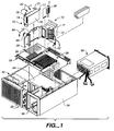
- Shroud 10 includes a vented cooling fan enclosure 11 in which a cooling fan 12 is mounted and a CPU front panel mount section 13, which positions a CPU module 14 relative to cooling fan 12.
- CPU module 14 includes a rectangular enclosure housing 16, in which is mounted a CPU and associated cooling fins (not shown). Housing 16 encloses the CPU and defines an inlet opening 15 and an outlet opening 17. Cooling air is drawn through inlet opening 15, across the cooling fins of the CPU, out the outlet opening 17 and into cooling fan enclosure 11.
- CPU module 14 also includes a pair of cam-action clips 19, 21, which clip onto front panel mount section 13, in a vertical plane as shown and indicated by arrows 23, and hold the CPU module down onto the shroud 10.
- Shroud 10 is secured to the motherboard 18 in a manner discussed further below with reference to Figs. 4, 5 and 6.
- a pair of captive fasteners 20, 22 are carried by shroud 10 and extend down through motherboard 18 and secure shroud 10 to chassis 24, thereby providing ground points for the motherboard.
- Motherboard 18 is positioned within chassis 24 by conventional slot means.
- Fig. 1 Additional computer components shown in Fig. 1 are conventional. These include power supply 30, drive bay 32, peripheral bay 34, PCI card slots 35, DSIMM Slots 36, audio card 38, and auxiliary fan compartment 40.
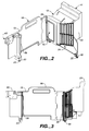
- shroud 10 can be seen to somewhat of an L-shaped component with a large foot compartment that is the vented cooling fan enclosure 11.
- the vented cooling fan enclosure 11 includes an outlet side 50 through which the cooling fan blows exhaust air to the exterior of chassis 24.
- Cooling fan enclosure 11 also includes a large, rectangular rear inlet opening 52, which receives air drawn across the CPU module housing, and additional slotted vents 54, which allow for air to be drawn from areas of the motherboard 18 in and around the DSIMMS.
- the front panel CPU mount 13 of shroud 10 forms the long leg of shroud 10 and includes a pair of opposed rails 56, 58, which are designed to capture side edges of CPU module housing 16 and thereby position the housing relative to the shroud.
- opposed rails 56, 58 CPU housing 16 is positioned with its outlet opening 17 aligned with the inlet opening 52 of cooling fan enclosure 11.
- the CPU plugs into a slot on the motherboard and is secured by the slot.
- Rails 56, 58 serve primarily to align the CPU module so that it stays fully plugged into the CPU slot on the motherboard and is properly positioned relative to the cooling fan.
- Shroud 10 also includes a swing clip 60, which is pivotally mounted at one end of the shroud, opposite cooling fan enclosure 11.
- Swing clip 60 includes a slot for receiving the edge of a fixed position flange, when the swing clip is pivoted in the direction of arrow 64 of Fig. 1 to the position of Fig. 2. Swing clip 60 and its cooperating flange are discussed in more detail with reference to Figs. 6, 8 and 9.
- the captive fasteners 20, 22 are secured to shroud 10 at fasteners mounts 63, 65, which extend down from shroud 10 and engage the motherboard and align with openings therein for the fasteners to extend through to the chassis.
- the CPU mount section 13 of shroud 10 also includes a handle grip 66, which allows shroud 10 to be easy grabbed and removed from the motherboard when interference hooks, discussed later, and the captive fasteners are released.
- Interference hooks 70, 72, 74 are mounted to shroud 10, one at the swing clip end underneath fastener mount 63 and adjacent captive fastener 20, another at the comer 76 of shroud 10, and the third at the vented enclosure end adjacent fastener mount 65 .
- Interference hooks 70, 72, 74 are L-shaped projections from shroud 10 that fit through keyhole openings in the motherboard and grab an edge of the openings as the shroud is shifted sideways, to lock the shroud onto the motherboard. Hooks 70, 72, 74 prevent outward movement of the shroud away from the motherboard.
- the interference hooks 70, 72, 74 can be easily released from the motherboard by sliding the shroud sideways, which releases the interfering legs of the hooks from the edges of the keyhole openings, allowing shroud 10 to be removed from the motherboard, upon release of the captive fasteners as well.
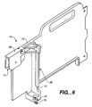
- Swing clip 60 includes a slot 71, which fits over a flange edge or other flat edge part of the chassis and thereby secures the upper edge of shroud 10 in position.
- Swing clip 60 supplements the positioning of the CPU module that is provided by rails 56, 58 and by the CPU connector itself.
- Rail 58 is formed by bracket portion 73 of shroud 10.
- the bottom portion of bracket 73 defines a captive housing 75 for one of the captive fasteners (not shown).
- Interference hook 70 extends down and outwardly from the bottom of bracket 73.
- the auxiliary fan compartment 40 is formed by a box-like enclosure in which is mounted an auxiliary fan (not shown).
- the auxiliary fan provides cooling air flow to the PCI card slots that are positioned on the side of shroud 10 opposite the CPU module.
- shroud 10 functions as an air flow divider, separating cooling air for the CPU module from the cooling air for the PCI card slots. This is discussed in more detail with reference to Fig. 10.
- a forwardly extending upright flange 84 is provided at the inside comer of compartment 40 and is fixedly mounted thereto.
- the swing clip 60 of the shroud pivots downwardly (or sideways if chassis 24 is upright) onto and straddles the upper edge 86 of flange 84.
- Flange 84 provides a fixed point at which to secure one end of the shroud, thereby securing the shroud in position on the motherboard, but also aligning the CPU module housing with cooling fan 12.
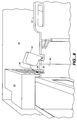
- Fig. 8 shows swing clip 60 in an up, released position.
- shroud 10 When shroud 10 is installed onto the motherboard, the inner edge 88 of shroud 10 butts against flange 84, whichpositions swing clip 60 to pivot from the position of Fig. 8 to a closed, locked position, as shown in Fig. 9.
- swing clip 60 In its locked position, swing clip 60 straddles the upper edge 86 of flange 84.
- the purpose of flange 84 is to provide a fixed mounting component within the chassis to which the shroud can be secured. Other fixed mounting points could be employed so long as they provide for alignment of the shroud and preferably also allow for quick disconnect of the shroud.
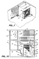
- auxiliary cooling fan is designated 90 and is mounted within compartment 40.
- -Compartment 40 along with shroud 10, form a dividing partition along broken line 92, which separates the cooling air of the PCI card side of the motherboard from the cooling air of the CPU module side of the motherboard.
- Air flow within the PCI card side is depicted by arrows 96, which flows through vents 102, 100, across PCI card slots 35, through vents 98, to the exterior of the chassis. Air flow on the CPU side of the shroud 10 flows generally in the same direction but does not substantially mix with cooling air over the PCI cards due to the separation of shroud 10.
- Arrows 104 depict the flow of cooling air across the CPU, and arrows 106 depict the flow of cooling air across DSIMMS 36, as well as other components of the motherboard.
- Arrows 108 depict the flow of cooling air provided by power supply fan 110. Vents 112, 114, 116 allow for front to back cooling air flow through peripheral bay 34 and power supply 30.
- the cooling air flow depicted by arrows 108 is not isolated from the CPU cooling air depicted by arrows 104 in the same manner as cooling air 104 is isolated from cooling air 96.
- a housing is provided for directing cooling air across the CPU and isolated compartments within the chassis allow for different cooling capacity for different parts of the system.
- the shroud attachment is a multipurpose component in that it positions the CPU module relative to a cooling fan, provides mounts for captive fasteners, which secure and electrically ground the motherboard, and creates a partition for isolating separate cooling air flows within the chassis. This combined, functional design of the shroud attachment simplifies the internal hardware design of the computer while enhancing cooling efficiency.
- the terms “down” and “up” refer to the relative positions of the components as shown in the figures.
- the computer shown is turned right side up, as a mini tower computer housing, and what is described as vertical, for example, then becomes horizontal.
Landscapes
- Engineering & Computer Science (AREA)
- Theoretical Computer Science (AREA)
- Human Computer Interaction (AREA)
- Physics & Mathematics (AREA)
- General Engineering & Computer Science (AREA)
- General Physics & Mathematics (AREA)
- Computer Hardware Design (AREA)
- Power Engineering (AREA)
- Cooling Or The Like Of Electrical Apparatus (AREA)
Applications Claiming Priority (2)
| Application Number | Priority Date | Filing Date | Title |
|---|---|---|---|
| US892504 | 1997-07-14 | ||
| US08/892,504 US5852547A (en) | 1997-07-14 | 1997-07-14 | Module shroud attachment to motherboard |
Publications (3)
| Publication Number | Publication Date |
|---|---|
| EP0892337A2 true EP0892337A2 (de) | 1999-01-20 |
| EP0892337A3 EP0892337A3 (de) | 1999-08-18 |
| EP0892337B1 EP0892337B1 (de) | 2005-01-26 |
Family
ID=25400034
Family Applications (1)
| Application Number | Title | Priority Date | Filing Date |
|---|---|---|---|
| EP98305549A Expired - Lifetime EP0892337B1 (de) | 1997-07-14 | 1998-07-13 | An einer Träger-Leitplatte zu befestigende Abdeckung |
Country Status (4)
| Country | Link |
|---|---|
| US (1) | US5852547A (de) |
| EP (1) | EP0892337B1 (de) |
| JP (1) | JPH11134068A (de) |
| DE (1) | DE69828726D1 (de) |
Cited By (3)
| Publication number | Priority date | Publication date | Assignee | Title |
|---|---|---|---|---|
| WO2001001229A1 (en) * | 1999-06-28 | 2001-01-04 | Sun Microsystems, Inc. | Computer system configuration |
| US6373697B1 (en) | 1999-06-28 | 2002-04-16 | Sun Microsystems, Inc. | Computer system housing and configuration |
| WO2002077788A1 (en) * | 2001-03-24 | 2002-10-03 | Michael Edwards | Computer system with plurality of display devices |
Families Citing this family (43)
| Publication number | Priority date | Publication date | Assignee | Title |
|---|---|---|---|---|
| US6130819A (en) * | 1998-01-29 | 2000-10-10 | Intel Corporation | Fan duct module |
| US6058009A (en) * | 1998-07-14 | 2000-05-02 | Dell Usa, L.P. | Computer with improved internal cooling system |
| US6038128A (en) * | 1998-07-14 | 2000-03-14 | Dell U.S.A., L.P. | Computer and computer/docking assembly with improved internal cooling |
| US6086476A (en) * | 1998-07-31 | 2000-07-11 | Compaq Computer Corporation | Method and apparatus for cooling and acoustic noise reduction in a computer |
| US6130820A (en) * | 1999-05-04 | 2000-10-10 | Intel Corporation | Memory card cooling device |
| US6296509B1 (en) * | 1999-06-28 | 2001-10-02 | Sun Microsystems, Inc. | Interconnect engagement and removal using a torque-limiting screw |
| US6330156B1 (en) | 1999-08-10 | 2001-12-11 | Micron Technology, Inc. | Card support and cooler bracket |
| TW453469U (en) * | 1999-10-12 | 2001-09-01 | Hon Hai Prec Ind Co Ltd | Computer fan holder |
| US6430041B1 (en) | 1999-10-20 | 2002-08-06 | Micronpc, Llc | Computer cooling system and method |
| US6288898B1 (en) | 1999-12-20 | 2001-09-11 | Dell Usa, L.P. | Apparatus for mounting and cooling a system components in a computer |
| US6292361B1 (en) | 1999-12-20 | 2001-09-18 | Dell Usa, L.P. | Apparatus and method for mounting and cooling a system component assembly in a computer |
| JP3660860B2 (ja) * | 2000-06-14 | 2005-06-15 | 株式会社日立製作所 | 情報処理装置 |
| JP3565767B2 (ja) * | 2000-07-19 | 2004-09-15 | トラストガード株式会社 | カートリッジ型サーバユニットおよび該サーバユニット搭載用筐体ならびにサーバ装置 |
| US6778390B2 (en) | 2001-05-15 | 2004-08-17 | Nvidia Corporation | High-performance heat sink for printed circuit boards |
| KR100423700B1 (ko) * | 2001-08-11 | 2004-03-18 | 잘만테크 주식회사 | 컴퓨터용 냉각팬 지지브라켓 |
| US6411511B1 (en) * | 2001-09-14 | 2002-06-25 | Portwell Inc. | Motherboard heat sink passage and support board |
| US6783325B1 (en) * | 2002-03-29 | 2004-08-31 | Sun Microsystems, Inc. | High air flow fan tray bracket |
| TW553411U (en) * | 2002-04-11 | 2003-09-11 | Avance Technologies Inc | Auxiliary positioning and heat sink device of interface card |
| DE10224273B4 (de) * | 2002-05-31 | 2004-07-15 | Fujitsu Siemens Computers Gmbh | Kühlanordnung für einen Tower-PC |
| US20040004812A1 (en) * | 2002-07-03 | 2004-01-08 | Dell Products L.P. | Pivotable processor shroud and method of use |
| US20040095723A1 (en) * | 2002-11-15 | 2004-05-20 | Enlight Corporation | Internal heat sink construction for CPU cabinet |
| US6999312B1 (en) * | 2003-03-31 | 2006-02-14 | Sun Microsystems, Inc. | Heatsink apparatus |
| US6921247B2 (en) * | 2003-04-14 | 2005-07-26 | Sun Microsystems, Inc. | Snap-together modular fan tray assembly for an electronics enclosure |
| EP1509041A1 (de) * | 2003-08-19 | 2005-02-23 | Medion AG | Multifunktionsgerät zur Audio/Videosignal-Verarbeitung |
| US7002797B1 (en) * | 2003-11-17 | 2006-02-21 | Nvidia Corporation | Noise-reducing blower structure |
| TWM249105U (en) * | 2003-12-22 | 2004-11-01 | Wistron Corp | Cooling module of computer system and related apparatus with air wall for preventing recycling of heated air |
| US20050207098A1 (en) * | 2004-03-16 | 2005-09-22 | Malone Christopher G | Electrical equipment housings having a horizontally mounted connection plane |
| US20060109624A1 (en) * | 2004-11-19 | 2006-05-25 | Kuo-Chuan Hung | Side-suction heat dissipating structure for an industrial computer |
| WO2006103731A1 (ja) * | 2005-03-28 | 2006-10-05 | Fujitsu Limited | 電子装置 |
| US20070139898A1 (en) * | 2005-12-16 | 2007-06-21 | Inventec Corporation | System motherboard having expansibility and variability |
| US20080113603A1 (en) * | 2006-10-19 | 2008-05-15 | Atallah Jean G | Computer system cooling system |
| US7408773B2 (en) * | 2006-11-27 | 2008-08-05 | Dell Products L.P. | Reinforced air shroud |
| CN201097303Y (zh) * | 2007-08-06 | 2008-08-06 | 鸿富锦精密工业(深圳)有限公司 | 具导风罩的散热组合 |
| TWM329948U (en) * | 2007-08-08 | 2008-04-01 | Cooler Master Co Ltd | Negative-pressure inhaling type computer heat-dissipating case |
| KR20110027766A (ko) * | 2008-07-09 | 2011-03-16 | 휴렛-팩커드 디벨롭먼트 컴퍼니, 엘.피. | 컴퓨터 섀시 챔버를 위한 전용의 공기 흡입구 및 공기 배출구 |
| CN201562214U (zh) * | 2009-10-14 | 2010-08-25 | 鸿富锦精密工业(深圳)有限公司 | 电子装置壳体 |
| EP2490097A4 (de) * | 2009-10-16 | 2014-06-18 | Fujitsu Ltd | Elektronische vorrichtung |
| CN201654650U (zh) * | 2010-01-04 | 2010-11-24 | 鸿富锦精密工业(深圳)有限公司 | 电子装置壳体 |
| CN102156516A (zh) * | 2010-02-11 | 2011-08-17 | 英业达股份有限公司 | 服务器系统 |
| TW201202651A (en) * | 2010-07-07 | 2012-01-16 | Hon Hai Prec Ind Co Ltd | Air duct for cooling a plurality of electronic components and electronic device using the same |
| TW201205026A (en) * | 2010-07-27 | 2012-02-01 | Hon Hai Prec Ind Co Ltd | Air duct and electronic device using the same |
| US8768532B2 (en) * | 2011-07-15 | 2014-07-01 | Microsoft Corporation | Indirect thermal fan control |
| DE112012005011T5 (de) | 2011-11-29 | 2014-08-28 | Cooper Technologies Co. | Luftleithaube für ein Elektrogehäuse |
Family Cites Families (7)
| Publication number | Priority date | Publication date | Assignee | Title |
|---|---|---|---|---|
| US5136465A (en) * | 1990-10-29 | 1992-08-04 | International Business Machines Corp. | Personal computer with tandem air flow dual fans and baffle directed air cooling |
| US5159528A (en) * | 1990-12-07 | 1992-10-27 | Compuadd Corporation | Modular personal computer |
| US5338214A (en) * | 1992-10-27 | 1994-08-16 | Steffes Karl M | Expansion card/riser card module for desktop computers |
| US5562410A (en) * | 1994-02-10 | 1996-10-08 | Emc Corporation | Self-aligning hot-pluggable fan assembly |
| TW265430B (en) * | 1994-06-30 | 1995-12-11 | Intel Corp | Ducted opposing bonded fin heat sink blower multi-microprocessor cooling system |
| US5497288A (en) * | 1994-08-31 | 1996-03-05 | International Business Machines Corporation | Apparatus for tilted serial cooling in an electronic system |
| US5523917A (en) * | 1994-09-06 | 1996-06-04 | Hewlett-Packard Co. | Power supply cover |
-
1997
- 1997-07-14 US US08/892,504 patent/US5852547A/en not_active Expired - Lifetime
-
1998
- 1998-07-13 EP EP98305549A patent/EP0892337B1/de not_active Expired - Lifetime
- 1998-07-13 DE DE69828726T patent/DE69828726D1/de not_active Expired - Lifetime
- 1998-07-14 JP JP10198575A patent/JPH11134068A/ja active Pending
Cited By (4)
| Publication number | Priority date | Publication date | Assignee | Title |
|---|---|---|---|---|
| WO2001001229A1 (en) * | 1999-06-28 | 2001-01-04 | Sun Microsystems, Inc. | Computer system configuration |
| US6373697B1 (en) | 1999-06-28 | 2002-04-16 | Sun Microsystems, Inc. | Computer system housing and configuration |
| US6542362B2 (en) | 1999-06-28 | 2003-04-01 | Sun Microsystems, Inc. | Computer system housing configuration |
| WO2002077788A1 (en) * | 2001-03-24 | 2002-10-03 | Michael Edwards | Computer system with plurality of display devices |
Also Published As
| Publication number | Publication date |
|---|---|
| EP0892337B1 (de) | 2005-01-26 |
| US5852547A (en) | 1998-12-22 |
| JPH11134068A (ja) | 1999-05-21 |
| DE69828726D1 (de) | 2005-03-03 |
| EP0892337A3 (de) | 1999-08-18 |
Similar Documents
| Publication | Publication Date | Title |
|---|---|---|
| EP0892337B1 (de) | An einer Träger-Leitplatte zu befestigende Abdeckung | |
| EP0896697B1 (de) | Gehäuse für einen personalcomputer mit befestigungssystem für peripheriegeräte | |
| US5375038A (en) | Computer tower unit having internal air flow control baffle structure | |
| US5886639A (en) | Memory storage device housing and cooling device | |
| US7206201B2 (en) | Memory storage device docking adapter having a laterally mounted fan | |
| US5707282A (en) | Fan diffuser | |
| US6058011A (en) | Computer chassis with integrated cooling features | |
| US8848364B2 (en) | Daughterboard having airflow path | |
| US6724624B1 (en) | Housing with directed-flow cooling for computer | |
| US6353536B1 (en) | Electronic equipment system and extension device for expanding the functions of electronic equipment | |
| US6552898B1 (en) | Fan duct module | |
| US5432674A (en) | Computer tower unit having internal air flow control baffle structure | |
| US5959841A (en) | Modular computer chassis with extractor device mounted to the housing | |
| US20110134605A1 (en) | Heat-dissipating hole mechanism capable of adjusting airflow rate and portable computer device thereof | |
| JP2009266222A (ja) | 熱管理用の装置および熱管理方法 | |
| US5751550A (en) | Ultra-quiet, thermally efficient cooling system for forced air cooled electronics | |
| EP1669840B1 (de) | Batteriesystem für tragbaren Rechner | |
| EP3494453A1 (de) | Erweiterungskartenanordnung | |
| JP2003015776A (ja) | 電子機器および電子機器の部品実装方法 | |
| EP0903065B1 (de) | Einrichtung und verfahren fur eine bessere luftzirkulation durch einen rahmengestell | |
| US20070230118A1 (en) | Circuit board including components aligned with a predominant air flow path through a chassis | |
| EP0520173A2 (de) | Computer Gehäuse | |
| US20050237713A1 (en) | Tower PC configuration | |
| US6626507B2 (en) | Fire shield for air ventilation holes of a computer chassis | |
| US5825620A (en) | Enhanced air cooling system with attached cooling unit |
Legal Events
| Date | Code | Title | Description |
|---|---|---|---|
| PUAI | Public reference made under article 153(3) epc to a published international application that has entered the european phase |
Free format text: ORIGINAL CODE: 0009012 |
|
| AK | Designated contracting states |
Kind code of ref document: A2 Designated state(s): DE FR GB IT NL SE |
|
| AX | Request for extension of the european patent |
Free format text: AL;LT;LV;MK;RO;SI |
|
| PUAL | Search report despatched |
Free format text: ORIGINAL CODE: 0009013 |
|
| AK | Designated contracting states |
Kind code of ref document: A3 Designated state(s): AT BE CH CY DE DK ES FI FR GB GR IE IT LI LU MC NL PT SE |
|
| AX | Request for extension of the european patent |
Free format text: AL;LT;LV;MK;RO;SI |
|
| 17P | Request for examination filed |
Effective date: 20000127 |
|
| AKX | Designation fees paid |
Free format text: DE FR GB IT NL SE |
|
| 17Q | First examination report despatched |
Effective date: 20020906 |
|
| RAP1 | Party data changed (applicant data changed or rights of an application transferred) |
Owner name: SUN MICROSYSTEMS, INC. |
|
| GRAP | Despatch of communication of intention to grant a patent |
Free format text: ORIGINAL CODE: EPIDOSNIGR1 |
|
| GRAS | Grant fee paid |
Free format text: ORIGINAL CODE: EPIDOSNIGR3 |
|
| GRAA | (expected) grant |
Free format text: ORIGINAL CODE: 0009210 |
|
| AK | Designated contracting states |
Kind code of ref document: B1 Designated state(s): DE FR GB IT NL SE |
|
| PG25 | Lapsed in a contracting state [announced via postgrant information from national office to epo] |
Ref country code: NL Free format text: LAPSE BECAUSE OF FAILURE TO SUBMIT A TRANSLATION OF THE DESCRIPTION OR TO PAY THE FEE WITHIN THE PRESCRIBED TIME-LIMIT Effective date: 20050126 Ref country code: IT Free format text: LAPSE BECAUSE OF FAILURE TO SUBMIT A TRANSLATION OF THE DESCRIPTION OR TO PAY THE FEE WITHIN THE PRESCRIBED TIME-LIMIT;WARNING: LAPSES OF ITALIAN PATENTS WITH EFFECTIVE DATE BEFORE 2007 MAY HAVE OCCURRED AT ANY TIME BEFORE 2007. THE CORRECT EFFECTIVE DATE MAY BE DIFFERENT FROM THE ONE RECORDED. Effective date: 20050126 Ref country code: FR Free format text: LAPSE BECAUSE OF FAILURE TO SUBMIT A TRANSLATION OF THE DESCRIPTION OR TO PAY THE FEE WITHIN THE PRESCRIBED TIME-LIMIT Effective date: 20050126 |
|
| REG | Reference to a national code |
Ref country code: GB Ref legal event code: FG4D |
|
| REF | Corresponds to: |
Ref document number: 69828726 Country of ref document: DE Date of ref document: 20050303 Kind code of ref document: P |
|
| PG25 | Lapsed in a contracting state [announced via postgrant information from national office to epo] |
Ref country code: SE Free format text: LAPSE BECAUSE OF FAILURE TO SUBMIT A TRANSLATION OF THE DESCRIPTION OR TO PAY THE FEE WITHIN THE PRESCRIBED TIME-LIMIT Effective date: 20050426 |
|
| PG25 | Lapsed in a contracting state [announced via postgrant information from national office to epo] |
Ref country code: DE Free format text: LAPSE BECAUSE OF FAILURE TO SUBMIT A TRANSLATION OF THE DESCRIPTION OR TO PAY THE FEE WITHIN THE PRESCRIBED TIME-LIMIT Effective date: 20050427 |
|
| NLV1 | Nl: lapsed or annulled due to failure to fulfill the requirements of art. 29p and 29m of the patents act | ||
| PLBE | No opposition filed within time limit |
Free format text: ORIGINAL CODE: 0009261 |
|
| STAA | Information on the status of an ep patent application or granted ep patent |
Free format text: STATUS: NO OPPOSITION FILED WITHIN TIME LIMIT |
|
| 26N | No opposition filed |
Effective date: 20051027 |
|
| EN | Fr: translation not filed | ||
| PGFP | Annual fee paid to national office [announced via postgrant information from national office to epo] |
Ref country code: GB Payment date: 20170712 Year of fee payment: 20 |
|
| REG | Reference to a national code |
Ref country code: GB Ref legal event code: PE20 Expiry date: 20180712 |
|
| PG25 | Lapsed in a contracting state [announced via postgrant information from national office to epo] |
Ref country code: GB Free format text: LAPSE BECAUSE OF EXPIRATION OF PROTECTION Effective date: 20180712 |