EP0892413A2 - Drucktaster - Google Patents
Drucktaster Download PDFInfo
- Publication number
- EP0892413A2 EP0892413A2 EP98111206A EP98111206A EP0892413A2 EP 0892413 A2 EP0892413 A2 EP 0892413A2 EP 98111206 A EP98111206 A EP 98111206A EP 98111206 A EP98111206 A EP 98111206A EP 0892413 A2 EP0892413 A2 EP 0892413A2
- Authority
- EP
- European Patent Office
- Prior art keywords
- ring
- button
- key
- push button
- flush
- Prior art date
- Legal status (The legal status is an assumption and is not a legal conclusion. Google has not performed a legal analysis and makes no representation as to the accuracy of the status listed.)
- Granted
Links
Images
Classifications
-
- H—ELECTRICITY
- H01—ELECTRIC ELEMENTS
- H01H—ELECTRIC SWITCHES; RELAYS; SELECTORS; EMERGENCY PROTECTIVE DEVICES
- H01H13/00—Switches having rectilinearly-movable operating part or parts adapted for pushing or pulling in one direction only, e.g. push-button switch
- H01H13/02—Details
- H01H13/12—Movable parts; Contacts mounted thereon
- H01H13/14—Operating parts, e.g. push-button
-
- H—ELECTRICITY
- H01—ELECTRIC ELEMENTS
- H01H—ELECTRIC SWITCHES; RELAYS; SELECTORS; EMERGENCY PROTECTIVE DEVICES
- H01H3/00—Mechanisms for operating contacts
- H01H3/02—Operating parts, i.e. for operating driving mechanism by a mechanical force external to the switch
- H01H3/12—Push-buttons
- H01H2003/127—Details of the key cap concerning the actuation by fingernails or having provision to allow usage with long fingernails
Definitions
- the invention relates to a push button according to the preamble of claim 1.
- Round push buttons with a diameter between 15 and 25 mm, which have a ring in which a spring-biased around a predetermined stroke
- the push button is arranged so that the top is flat Button is flush with the top edge of the ring are known.
- the ring is used to attach the button to a mounting surface and also for finger guidance for safe and clear operation as well as protection against incorrect operation due to unintentional touch.
- Elimination of this problem is a reduction the actuation stroke of the key. On the one hand, however, this requires a certain amount Fine motor skills and on the other hand an acoustic or visual feedback the push of a button.
- the button would protrude so that the ring functions as a finger guide and Protection against incorrect operation would lose.
- the object of the invention is a push button according to the preamble of claim 1 to create a convenient operation of the button even with long fingernails, without the function the ring as a finger guide and misuse protection is lost or feedback is required.
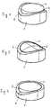
- the round push buttons with an outside diameter in the range of about 15 to 25 mm a ring 1, which basically serves to open the push button to attach a mounting surface.
- the ring 1 takes a button 2 with it planer top 3, which can be pressed in by a predetermined actuation stroke is arranged in the ring 1.
- the ring 1 has a circumferential upper edge 4 which opposite sides parallel to the longitudinal axis of an actuating finger of an actuator has a reduced height, so that the upper Edge 4, whose upper edge is flush with the flat top 3 of the key 2 is, from the top edge, from two opposite points is formed perpendicular to the longitudinal axis of the actuating finger, where the Edge 4 runs flush with the flat top 3 of key 2, up to a depth that corresponds approximately to the actuation stroke of the key 2, gradually lowers. Because the fingernail is slightly higher than that when actuated The fingertip with which the operation is carried out can be the intended one Height difference should be slightly smaller than the actuation stroke of button 2.
- the ring is 1st only reduced in height on one side.
- the ring is 1st as in Fig. 1, but the surface 3 of the key 2 is on adapted the upper edge 4 of the ring 1 so that they are flush with this is.
Landscapes
- Push-Button Switches (AREA)
Abstract
Description
Claims (4)
- Drucktaster mit einem Ring (1), in dem um einen vorbestimmten Betätigungshub eine federvorgespannte Taste (2) eindrückbar angeordnet ist, wobei die Taste (2) mit der oberen Kante des Rings (1) bündig abschließt, dadurch gekennzeichnet, daß der Ring (1) an wenigstens einer Seite parallel zur Längsachse eines Betätigungsfingers in seiner Höhe fortschreitend bis etwa zum Betätigungshub verringert ist.
- Drucktaster nach Anspruch , dadurch gekennzeichnet, daß der Ring (1) an zwei gegenüberliegenden Seiten in seiner Höhe gleich verringert ist.
- Drucktaster nach Anspruch 2, dadurch gekennzeichnet, daß die Oberseite (3) der Taste (2) plan ist.
- Drucktaster nach Anspruch 2, dadurch gekennzeichnet, daß die Oberseite (3) der Taste (2) entsprechend der Kontur des oberen Randes (4) des Rings (1) ausgebildet ist und bündig hiermit ist.
Applications Claiming Priority (2)
| Application Number | Priority Date | Filing Date | Title |
|---|---|---|---|
| DE19730680 | 1997-07-17 | ||
| DE19730680A DE19730680C1 (de) | 1997-07-17 | 1997-07-17 | Drucktaster |
Publications (3)
| Publication Number | Publication Date |
|---|---|
| EP0892413A2 true EP0892413A2 (de) | 1999-01-20 |
| EP0892413A3 EP0892413A3 (de) | 1999-08-18 |
| EP0892413B1 EP0892413B1 (de) | 2002-11-27 |
Family
ID=7836025
Family Applications (1)
| Application Number | Title | Priority Date | Filing Date |
|---|---|---|---|
| EP98111206A Expired - Lifetime EP0892413B1 (de) | 1997-07-17 | 1998-06-18 | Drucktaster |
Country Status (5)
| Country | Link |
|---|---|
| US (1) | US6087605A (de) |
| EP (1) | EP0892413B1 (de) |
| JP (1) | JPH1186671A (de) |
| BR (1) | BR9802485A (de) |
| DE (2) | DE19730680C1 (de) |
Families Citing this family (30)
| Publication number | Priority date | Publication date | Assignee | Title |
|---|---|---|---|---|
| USD461813S1 (en) | 2000-06-30 | 2002-08-20 | 3Com Corporation | Concave pushbutton |
| US6375187B1 (en) * | 2000-10-06 | 2002-04-23 | Igt | Gaming device having improved offer and acceptance bonus scheme |
| US7089096B2 (en) * | 2000-10-17 | 2006-08-08 | Spx Corporation | Apparatus and method for displaying diagnostic values |
| US6640166B2 (en) * | 2000-10-17 | 2003-10-28 | Spx Corporation | Diagnostic tool graphical display apparatus and method |
| DE10052017B4 (de) * | 2000-10-20 | 2005-02-24 | Ilgner, Justus, Dr.med. | Nystagmusbrille |
| USD511752S1 (en) * | 2004-09-02 | 2005-11-22 | Memie Mei Mei Wong | Electrical switch |
| US7521642B2 (en) * | 2006-02-06 | 2009-04-21 | Toyota Motor Engineering & Manufacturing North America, Inc. | Switch assembly for an automotive power window |
| US20070278229A1 (en) * | 2006-06-01 | 2007-12-06 | William Li | Container lid with push button operation |
| TW200843642A (en) * | 2007-03-08 | 2008-11-16 | Du Pont | Liquid sulfonylurea herbicide formulations |
| USD606546S1 (en) * | 2007-09-26 | 2009-12-22 | Fujitsu Limited | Personal computer |
| USD593510S1 (en) * | 2008-04-17 | 2009-06-02 | E-Lead Electronics Co., Ltd. | Vehicle communication controller |
| USD685333S1 (en) * | 2012-07-20 | 2013-07-02 | Raffel Systems, Llc | Control switch |
| USD691098S1 (en) * | 2012-10-04 | 2013-10-08 | Raffel Systems, Llc | Switch |
| USD700150S1 (en) * | 2013-02-18 | 2014-02-25 | Raffel System, LLC | Switch |
| USD707640S1 (en) * | 2013-02-18 | 2014-06-24 | Raffel Systems, Llc | Switch |
| USD691099S1 (en) * | 2013-02-18 | 2013-10-08 | Raffel Systems, Llc | Switch |
| USD691971S1 (en) * | 2013-02-18 | 2013-10-22 | Raffel Systems, Llc | Switch |
| USD692401S1 (en) * | 2013-02-18 | 2013-10-29 | Raffel Systems, Llc | Switch |
| USD692841S1 (en) * | 2013-02-18 | 2013-11-05 | Raffel Systems, Llc | Switch |
| KR20150012690A (ko) * | 2013-07-26 | 2015-02-04 | 삼성전자주식회사 | 키 버튼 및 그 제조 방법 |
| USD720305S1 (en) * | 2013-08-09 | 2014-12-30 | eMoMo Technology Co., Ltd. | Controller for smart furniture |
| USD714233S1 (en) * | 2013-11-04 | 2014-09-30 | Raffel Systems, Llc | Switch |
| USD712848S1 (en) * | 2013-11-04 | 2014-09-09 | Raffel Systems, Llc | Switch |
| USD729179S1 (en) * | 2014-01-24 | 2015-05-12 | Crestron Electronics Inc. | Two-button keypad |
| USD748590S1 (en) | 2014-08-19 | 2016-02-02 | Raffel Systems, Llc | Switch |
| JP1624108S (de) * | 2018-07-11 | 2019-02-12 | ||
| JP1624111S (de) * | 2018-07-11 | 2019-02-12 | ||
| USD928731S1 (en) * | 2019-04-18 | 2021-08-24 | Doosan Infracore Co., Ltd. | Start button for construction machinery |
| USD957354S1 (en) * | 2019-09-16 | 2022-07-12 | Helen Of Troy Limited | Beauty tool switch |
| EP3825777B1 (de) * | 2019-11-21 | 2024-04-24 | Meco S.A. | Korrekturvorrichtung einer armbanduhr und armbanduhrgehäuse |
Family Cites Families (8)
| Publication number | Priority date | Publication date | Assignee | Title |
|---|---|---|---|---|
| US2484886A (en) * | 1948-03-25 | 1949-10-18 | Henry Beulah Louise | Key for key operated machines |
| US2908776A (en) * | 1957-02-07 | 1959-10-13 | Cutler Hammer Inc | Operating means for electric circuit controlling devices |
| US3974351A (en) * | 1975-05-16 | 1976-08-10 | Irving Solov | Wrist watch push-button device |
| GB1503139A (en) * | 1976-11-25 | 1978-03-08 | Hugin Kassaregister Ab | Key for a keyboard |
| US4297556A (en) * | 1979-02-21 | 1981-10-27 | Taylor Glenn R | Pushbutton operator |
| US5134259A (en) * | 1990-04-25 | 1992-07-28 | Page Jr Lawrence C | Palm button switch apparatus |
| US5201409A (en) * | 1990-09-04 | 1993-04-13 | Inventio Ag | Vandal resistant push button assembly |
| USD343392S (en) | 1991-09-24 | 1994-01-18 | Logitech Inc. | Computer mouse |
-
1997
- 1997-07-17 DE DE19730680A patent/DE19730680C1/de not_active Expired - Lifetime
-
1998
- 1998-06-18 DE DE59806407T patent/DE59806407D1/de not_active Expired - Fee Related
- 1998-06-18 EP EP98111206A patent/EP0892413B1/de not_active Expired - Lifetime
- 1998-06-29 JP JP10182546A patent/JPH1186671A/ja active Pending
- 1998-07-16 US US09/116,394 patent/US6087605A/en not_active Expired - Fee Related
- 1998-07-16 BR BR9802485-0A patent/BR9802485A/pt not_active IP Right Cessation
Also Published As
| Publication number | Publication date |
|---|---|
| DE19730680C1 (de) | 1998-05-28 |
| BR9802485A (pt) | 1999-09-21 |
| EP0892413A3 (de) | 1999-08-18 |
| JPH1186671A (ja) | 1999-03-30 |
| EP0892413B1 (de) | 2002-11-27 |
| DE59806407D1 (de) | 2003-01-09 |
| US6087605A (en) | 2000-07-11 |
Similar Documents
| Publication | Publication Date | Title |
|---|---|---|
| EP0892413B1 (de) | Drucktaster | |
| EP4009659A1 (de) | Gehörschützer mit headset-funktion | |
| DE20118242U1 (de) | Papierlocher mit mehreren Stanzgliedern | |
| DE20009671U1 (de) | Dosendeckel | |
| DE60107058T2 (de) | Gasfeuerzeug mit kindersicherung | |
| DE20314064U1 (de) | Eingabevorrichtung mit integrierter Tastenfläche und integrierten Seitengriffen | |
| DE3027736C2 (de) | Fokussiermechanismus für ein Fernglas | |
| DE112019001247B4 (de) | Seitlich schneidender Dosenöffner | |
| DE60017048T2 (de) | Pyrophorfeuerzeug | |
| CH617097A5 (de) | ||
| DE19940386C2 (de) | Drucktaste | |
| DE69404058T2 (de) | Sichtheitsschalter für elektrische Fensterheber | |
| DE3044847A1 (de) | Eingabeeinheit fuer einen bordcomputer eines kraffahrzeugs | |
| EP2141417A2 (de) | Hausgerätetür mit einer Abdeckung für eine Frontglasscheibe | |
| DE19609940C2 (de) | Tastatur-Reinigungsgerät mit höheneinstellbaren Bürsten-Einsätzen im Druck- und Einrastverfahren | |
| DE20209870U1 (de) | Skalpell | |
| DE1782180A1 (de) | Betaetigungsvorrichtung fuer das Raedchen eines Feuerzeuges | |
| DE29504563U1 (de) | Nietwerkzeug | |
| DE3604574C1 (en) | Pipe notching device | |
| DE102018211111A1 (de) | Sicherheitssteuervorrichtung, Fahrzeuginnenverkleidungsteil umfassend eine entsprechende Sicherheitssteuervorrichtung und Verfahren zum Steuern eines Schließvorgangs und/oder Öffnungsvorgangs eines Fahrzeugfensters | |
| DE3019361C2 (de) | Vorrichtung zum Aufspannen von Blättern | |
| DE2733945A1 (de) | Schneidwerkzeug und verfahren zu seiner herstellung | |
| DE3540200C2 (de) | Fingerhut | |
| EP0280858B1 (de) | Brieflocher | |
| DE2748869C3 (de) | Einrichtung zum Unterbrechen des Stromkreises von elektrisch angetriebenen Schreib- o.a. Büromaschinen |
Legal Events
| Date | Code | Title | Description |
|---|---|---|---|
| PUAI | Public reference made under article 153(3) epc to a published international application that has entered the european phase |
Free format text: ORIGINAL CODE: 0009012 |
|
| AK | Designated contracting states |
Kind code of ref document: A2 Designated state(s): DE FR GB IT |
|
| AX | Request for extension of the european patent |
Free format text: AL;LT;LV;MK;RO;SI |
|
| PUAL | Search report despatched |
Free format text: ORIGINAL CODE: 0009013 |
|
| AK | Designated contracting states |
Kind code of ref document: A3 Designated state(s): AT BE CH CY DE DK ES FI FR GB GR IE IT LI LU MC NL PT SE |
|
| AX | Request for extension of the european patent |
Free format text: AL;LT;LV;MK;RO;SI |
|
| 17P | Request for examination filed |
Effective date: 19991028 |
|
| AKX | Designation fees paid |
Free format text: DE FR GB IT |
|
| GRAG | Despatch of communication of intention to grant |
Free format text: ORIGINAL CODE: EPIDOS AGRA |
|
| 17Q | First examination report despatched |
Effective date: 20020220 |
|
| GRAG | Despatch of communication of intention to grant |
Free format text: ORIGINAL CODE: EPIDOS AGRA |
|
| GRAH | Despatch of communication of intention to grant a patent |
Free format text: ORIGINAL CODE: EPIDOS IGRA |
|
| GRAH | Despatch of communication of intention to grant a patent |
Free format text: ORIGINAL CODE: EPIDOS IGRA |
|
| GRAA | (expected) grant |
Free format text: ORIGINAL CODE: 0009210 |
|
| AK | Designated contracting states |
Kind code of ref document: B1 Designated state(s): DE FR GB IT |
|
| PG25 | Lapsed in a contracting state [announced via postgrant information from national office to epo] |
Ref country code: IT Free format text: LAPSE BECAUSE OF FAILURE TO SUBMIT A TRANSLATION OF THE DESCRIPTION OR TO PAY THE FEE WITHIN THE PRESCRIBED TIME-LIMIT;WARNING: LAPSES OF ITALIAN PATENTS WITH EFFECTIVE DATE BEFORE 2007 MAY HAVE OCCURRED AT ANY TIME BEFORE 2007. THE CORRECT EFFECTIVE DATE MAY BE DIFFERENT FROM THE ONE RECORDED. Effective date: 20021127 |
|
| REG | Reference to a national code |
Ref country code: GB Ref legal event code: FG4D Free format text: NOT ENGLISH |
|
| GBT | Gb: translation of ep patent filed (gb section 77(6)(a)/1977) |
Effective date: 20021205 |
|
| REF | Corresponds to: |
Ref document number: 59806407 Country of ref document: DE Date of ref document: 20030109 |
|
| ET | Fr: translation filed | ||
| PG25 | Lapsed in a contracting state [announced via postgrant information from national office to epo] |
Ref country code: GB Free format text: LAPSE BECAUSE OF NON-PAYMENT OF DUE FEES Effective date: 20030618 |
|
| PLBE | No opposition filed within time limit |
Free format text: ORIGINAL CODE: 0009261 |
|
| STAA | Information on the status of an ep patent application or granted ep patent |
Free format text: STATUS: NO OPPOSITION FILED WITHIN TIME LIMIT |
|
| 26N | No opposition filed |
Effective date: 20030828 |
|
| PG25 | Lapsed in a contracting state [announced via postgrant information from national office to epo] |
Ref country code: DE Free format text: LAPSE BECAUSE OF NON-PAYMENT OF DUE FEES Effective date: 20040101 |
|
| GBPC | Gb: european patent ceased through non-payment of renewal fee |
Effective date: 20030618 |
|
| PG25 | Lapsed in a contracting state [announced via postgrant information from national office to epo] |
Ref country code: FR Free format text: LAPSE BECAUSE OF NON-PAYMENT OF DUE FEES Effective date: 20040227 |
|
| REG | Reference to a national code |
Ref country code: FR Ref legal event code: ST |