EP0892418B1 - Interrupteur manoeuvrable comme coulisseau que comme bouton poussoir et méthode d'assemblage - Google Patents
Interrupteur manoeuvrable comme coulisseau que comme bouton poussoir et méthode d'assemblage Download PDFInfo
- Publication number
- EP0892418B1 EP0892418B1 EP98112491A EP98112491A EP0892418B1 EP 0892418 B1 EP0892418 B1 EP 0892418B1 EP 98112491 A EP98112491 A EP 98112491A EP 98112491 A EP98112491 A EP 98112491A EP 0892418 B1 EP0892418 B1 EP 0892418B1
- Authority
- EP
- European Patent Office
- Prior art keywords
- rod
- spring
- slider
- push
- casing
- Prior art date
- Legal status (The legal status is an assumption and is not a legal conclusion. Google has not performed a legal analysis and makes no representation as to the accuracy of the status listed.)
- Expired - Lifetime
Links
Images


Classifications
-
- H—ELECTRICITY
- H01—ELECTRIC ELEMENTS
- H01H—ELECTRIC SWITCHES; RELAYS; SELECTORS; EMERGENCY PROTECTIVE DEVICES
- H01H25/00—Switches with compound movement of handle or other operating part
Definitions
- the present invention relates to a switch arrangement operable in both slide and push directions preferably used in various electronic devices, and its assembling method.
- a principal object of the present invention is to provide a multidirectional switch that is small in the number of used springs, easy to install, and inexpensive in costs.
- Another object of the present invention is to provide an assembling method for the multidirectional switch.
- the present invention provides a multidirectional switch operable in both slide and push, having various aspects which will be described hereinafter.
- a boxlike casing has an open top and an opening partly formed on a front wall thereof.
- a plurality of stationary contacts are provided on an inner bottom surface of the casing.
- a slider is installed in the casing and slidable in a predetermined slide direction.
- a rod is installed in a rod guide portion provided at a predetermined portion of the slider and slidable in a push direction normal to the slide direction.
- the rod has an operating lever protruding forward from the opening of the casing and a push portion extending rearward.
- At least one elastic contact piece is fixed to at least one of lower surfaces of the slider and the rod for electrically connecting or disconnecting the stationary contacts.
- Two L-shaped springs have proximal portions held by spring holders and first and second arms. The first arms have distal ends supported by spring receive portions and mesial portions received by arm receive portions. And, the second arms are pressed by the push portion of the rod movable in the push direction.
- the spring holders may be stationarily provided at left and right ends in the casing or on a lower surface of the cover.
- the spring receive portions may be provided at left and right ends of the slider movable in the slide direction.
- the arm receive portions may be provided at left and right portions of a lower surface of the cover.
- the spring holders may be provided at left and right ends of the slider movable in the slide direction.
- the arm receive portions may be provided at left and right ends of the slider.
- the spring receive portions may be provided stationarily in the casing independent of the slide movement of the slider.
- the multidirectional switch further comprises a push member slidably interposed between the rod and the two springs.
- the push member has a front face abutting the push portion of the rod and spring push portions pushing the second arms of the two springs.
- the first arms of the two spring have bent portions supported by corresponding spring receive portions of the slider.
- the plurality of stationary contacts comprises first stationary contacts and second stationary contacts align in parallel with the slide direction.
- the second stationary contacts align centrally on the inner bottom surface of the casing.
- the first stationary contacts position closely to the opening of the casing than the second stationary contacts.
- only one contact piece is exclusively located above the first stationary contacts and fixed to the lower surface of the rod.
- a protrusion is provided on the rod movable in the push direction and a recess is provided stationarily at a predetermined portion independent of the push movement of the rod, so that the protrusion of the rod can be guided and received by the recess only when the rod is depressed at a position where the protrusion faces the recess.
- the protrusion may be provided on a top surface of the rod and the recess may be provided on a front edge of the cover.
- the protrusion may be provided on a bottom surface of the rod and the recess may be provided on a front wall of the casing.
- the protrusion may be provided on a rear end of the rod and the recess may be provided on a rear wall of the casing.
- the slider has spring push portions at a rear end thereof for supporting mesial portions of the first arms of the two springs during the slide movement of the slider.
- Another aspect of the present invention provides an assembling method for the above-described multidirectional switch, comprising the following steps.
- a united spring is installed into the casing.
- the united spring has a connecting portion where the two L-shaped springs are integrally connected at distal ends of the second arms. Then, in a second step, the connecting portion of the united spring is pushed by the rod to separate the united spring into two independent L-shaped springs.
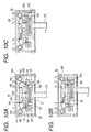
- Fig. 15 shows a perspective view showing an appearance of a switch operable in both slide and push directions.
- a boxlike casing 15 has a front wall having an opening 15A through which an operating lever 17A of a rod 17 protrudes forward.
- the operating lever 17A is operable from its neutral position toward both a slide direction (i.e., right-and-left direction) and a push direction (i.e., back-and-forth direction) that are normal each other.
- slide direction i.e., right-and-left direction
- a push direction i.e., back-and-forth direction
- Fig. 1 is a plan view showing a multidirectional switch in accordance with a first embodiment, wherein a cover 11 is removed off the boxlike casing 15.
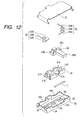
- Fig. 2 is an exploded perspective view showing respective parts of the multidirectional switch shown in Fig. 1.
- the boxlike casing 15, configured in an opened top shape, has the opening 15A provided on a front wall thereof.
- the casing 15 has a bottom.
- a plurality of contacts serving as first stationary contacts 2A, 2B and 2C align in the slide direction.
- Another contacts, serving as second stationary contacts 3A and 3B align in parallel to the first stationary contacts 2A, 2B and 2C as well as the opening 15A.
- the second stationary contacts 3A and 3B position closely to the opening 15A than the first stationary contacts 2A, 2B and 2C.
- a slider 16 is slidably installed in the casing 15.
- a rod 17 has an operating lever 17A protruding forward from the opening 15A of the casing 15.
- the rod 17 is slidable in a rod guide recess 16A formed on the upper surface of the slider 16.
- the rod 17 can move in both the slide direction and the push direction.
- the rod 17 has a rear end portion serving as a push portion 17B.
- Two cylindrical spring holders 15B and 15C position at the right and left ends on the inner bottom surface of the casing 15, respectively.
- An guide groove 15D interposes between the spring holders 15B and 15C.
- a push member 18 positions in the guide groove 15D.
- the push member 18 has a front face abutting the push portion 17B of the rod 17.
- the A push member 18 is slidable in the push direction along the bottom surface of the guide groove 15D.
- substantially L-shaped springs 19 and 20 have proximal portions 19A and 20A held by the spring holders 15B and 15C of the casing 15, respectively.
- the springs 19 and 20 have first arms 19B and 20B, respectively.
- the first arms 19B and 20B have bent portions 19C and 20C at the distal ends thereof.
- Spring receive portions 16B and 16C provided at the left and right sides of the slider 16 support the bent portions 19C and 20C, respectively.
- Spring push portions 18A and 18B, formed at left and right rear ends of the push member 18 support the second arms 19D and 20D, respectively.
- a first contact piece 6 is an elastic metal plate fixed to the lower surface of the slider 16. The first contact piece 6 is brought into contact with the first stationary contacts 2A, 2B and 2C.
- a second contact piece 7 is an elastic metal plate fixed to the lower surface of the rod 17. The second contact piece 7 is brought into contact with the second stationary contacts 3A and 3B.
- the operating lever 17A of the rod 17 protrudes forward from the opening 15A of the casing 15.
- the slider 16 slides rightward together with the rod 17 accommodated in the rod guide recess 16A as shown in Fig. 3A.
- the first contact piece 6 electrically connects the first stationary contacts 2B and 2C.
- the bent portion 19C of the left spring 19 departs from the spring receive portion 16B of the slider 16.
- the spring receive portion 16C pushes the bent portion 20C and resiliently compresses the first arm 20B.
- the right spring 20 stores the elastic restoring force when the first arm 20B is elastically compressed by the spring receive portion 16C of the slider 16.
- the compressed right spring 20 resiliently pushes the slider 16 and the accommodated rod 17 back to the neutral position shown in Fig. 1 by the elastic restoring force stored in the first arm 20B.
- the first stationary contacts 2B and 2C are electrically disconnected.
- the user can move the operating lever 17A left from the neutral position shown in Fig. 1.
- the slider 16 slides leftward together with the rod 17.
- the bent portion 20C of the right spring 20 departs from the spring receive portion 16C of the slider 16.
- Only the arm receive portion 11B of the cover 11 supports the mesial portion of the first arm 20B of the left spring 19.
- the mesial portion of the first arm 19B of the left spring 19 departs from the arm receive portion 11A of the cover 11.
- the spring receive portion 16B pushes the bent portion 19C and resiliently compresses the first arm 19B.
- the first contact piece 6 electrically connects the first stationary contacts 2A and 2B.
- the left spring 19 stores the elastic restoring force when the first arm 19B is elastically compressed by the spring receive portion 16B of the slider 16.
- the compressed left spring 19 resiliently pushes the slider 16 and the rod 17 back to the neutral position shown in Fig. 1 by the elastic restoring force stored in the first arm 19B.
- the first stationary contacts 2A and 2B are electrically disconnected.
- the user can depress the operating lever 17A in the push direction normal to the slide direction from the neutral position shown in Fig. 1.
- the push portion 17B formed at the rear end of the rod 17 pushes the front face of the push member 18.
- the spring push portions 18A and 18B compress the distal ends of the second arms 19D and 20D of the left and right springs 19 and 20, respectively.
- the rod 17 slides rearward in the rod guide recess 16A.
- the left and right springs 19 and 20 store the elastic restoring forces when their second arms 19D and 20D are elastically compressed by the spring push portions 18A and 18B, respectively.
- the compressed springs 19 and 20 resiliently push the rod 17 back to the neutral position shown in Fig. 1 by the elastic restoring forces stored in the second arms 19D and 20D.
- the slider 16 positions the rightmost position to electrically connect the first stationary contacts 2B and 2C via the first contact piece 6.
- the second contact piece 7 electrically connects the second stationary contacts 3A and 3B, as shown in Fig. 3C.
- the L-shaped springs 19 and 20 have the proximal portions 19A and 20A held by the spring holders 15B and 15C at the left and right ends on the inner bottom surface of the casing 15, respectively.
- the spring receive portions 16B and 16C of the slider 16 support the distal ends of the first arms 19B and 20B, respectively.
- the arm receive portions 11A and 11B of the cover 11 support the mesial portions of the first arms 19B and 20B, respectively.
- the spring push portions 18A and 18B of the push member 18 support the second arms 19D and 20D, respectively.
- the total number of the used springs can be minimized to two.
- the springs 19 and 20 are slightly compressed and installed in the casing 15 accommodating the slider 16. This installation can be easily done from the top of the casing 15.
- the simplified assembling method reduces the cost of the multidirectional switch.
- the springs 19 and 20 have bent portions 19C and 20C formed at the distal ends of the first arms 19B and 20B, respectively.
- the spring receive portions 16B and 16C provided at the left and right ends of the slider 16 support the bent portions 19C and 20C along their entire length, respectively. This arrangement enlarges the contact area between the slider 16 and the springs 19 and 20.
- the slider 16 surely compresses the first arms 19B and 20B of the springs 19 and 20.
- the bent portions 19C and 20C can be surely supported by the spring receive portions 16B and 16C of the slider 16. This prevents the springs 19 and 20 from jumping out of the slider 16.
- the cylindrical spring holders 15B and 15C formed on the inner bottom of the casing 15 support the proximal portions 19A and 20A of the L-shaped springs 19 and 20, respectively.
- the spring holders 11C and 11D protrude from the left and right ends of the cover 11 to support the proximate portions 19A and 20A of the springs 19 and 20.
- a boxlike casing (15) with an open top has an opening (15A) partly formed on a front wall thereof and a plurality of stationary contacts (2A ⁇ 2C, 3A ⁇ 3B) provided on an inner bottom surface thereof.
- a slider (16) is installed in the casing and slidable in a predetermined slide direction.
- the slider has a rod guide portion (16A) provided at a predetermined portion thereof and spring receive portions (16B, 16C) provided at left and right ends thereof.
- a rod (17) is installed in the rod guide portion and slidable in a push direction normal to the slide direction.
- the rod has an operating lever (17A) protruding forward from the opening of the casing and a push portion (17B) extending rearward.
- At least one elastic contact piece (6 or 7) is fixed to at least one of lower surfaces of the slider and the rod for electrically connecting or disconnecting the stationary contacts.
- Two L-shaped springs (19, 20) have proximal portions (19A, 20A) held by spring holders (15B, 15C; 11C, 11D) stationarily provided at predetermined left and right portions.
- the two springs have first arms (19B, 20B) and second arms (19D, 20D).
- the first arms (19B, 20B) have distal ends supported by the spring receive portions (16B, 16C) of the slider movable in the slide direction and mesial portions received by arm receive portions (11A, 11B) stationarily provided independent of the slide movement of the slider.
- the second arms (19D, 20D) are pressed by the push portion (17B) of the rod movable in the push direction.
- the multidirectional switch of the present invention comprises a push member (18) slidably interposed between the rod and the springs.
- the push member has a front face abutting the push portion (17B) of the rod and spring push portions (18A, 18B) pushing the second arms of the springs.
- the first arms of the two springs have bent portions (19C, 20C) supported by corresponding spring receive portions (16B, 16C) of the slider.
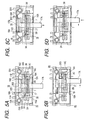
- Figs. 5A to 5D are plan views showing various operated conditions of the multidirectional switch in accordance with a second embodiment, wherein the cover is removed off the boxlike casing.
- the casing 15 accommodates the slider 16.
- the rod 17 is slidable in the rod guide recess 16A of the slider 16.
- the casing 15 has the cylindrical spring holders 15B and 15C that support the proximal portions 19A and 20A of the springs 19 and 20, respectively.
- the spring receive portions 16B and 16C of the slider 16 support the distal ends of the first arms 19B and 20B, respectively.
- the arm receive portions 11A and 11B of the cover 11 support the mesial portions of the first arms 19B and 20B, respectively.
- the spring push portions 18A and 18B of the push member 18 press the second arms 19D and 20D, respectively.
- the first stationary contacts 2A, 2B and 2C and the second stationary contacts 3A and 3B align on the inner bottom surface of the casing 15 in parallel to the slide direction of the slider 16.
- the second embodiment differs from the first embodiment in that the second stationary contacts 3A and 3B align at substantially the center of the inner bottom surface.
- the first stationary contacts 2A, 2B and 2C position closely to the opening 15A than the second stationary contacts 3A and 3B.
- the operating lever 17A of the rod 17 protrudes forward from the opening 15A of the casing 15.
- the slider 16 slides rightward together with the rod 17 accommodated in the rod guide recess 16A as shown in Fig. 5B.
- the spring receive portion 16C of the slider 16 resiliently compresses the first arm 20B of the right spring 20 in the same manner as explained in the first embodiment.
- the second contact piece 7, fixed to the lower surface of the rod 17, resiliently slides on the surfaces of the first stationary contacts provided on the inner bottom surface closely to the opening 15A of the casing 15.
- the second contact piece 7 electrically connects the first stationary contacts 2B and 2C.
- the compressed right spring 20 resiliently pushes the slider 16 and the accommodated rod 17 back to the neutral position shown in Fig. 5A by the elastic restoring force stored in the first arm 20B.
- the user can move the operating lever 17A left from the neutral position shown in Fig. 5A.
- the spring receive portion 16B of the slider 16 resiliently compresses the first arm 19B of the left spring 19.
- the user can depress the operating lever 17A in the push direction normal to the slide direction from the neutral position shown in Fig. 5A.
- the push portion 17B of the rod 17 pushes the push member 18 rearward.
- the spring push portions 18A and 18B compress the second arms 19D and 20D of the springs 19 and 20, respectively.
- the rod 17 slides rearward in the rod guide recess 16A.
- the second contact piece 7 leaves the first stationary contact 2B.
- the second contact piece 7 electrically connects the second stationary contacts 3A and 3B.
- the compressed springs 19 and 20 resiliently push the rod 17 back to the neutral position shown in Fig. 5A by the elastic restoring forces stored in the second arms 19D and 20D.
- the first stationary contacts 2A-2C and the second stationary contacts 3A ⁇ 3B align on the inner bottom surface of the casing 15 in parallel to the slide direction of the slider 16.
- the second stationary contacts 3A and 3B align at substantially the center of the inner bottom surface.
- the first stationary contacts 2A, 2B and 2C position closely to the opening 15A than the second stationary contacts 3A and 3B. No contact piece is fixed to the slider 16. Only one contact piece (i.e., the second contact piece 7 fixed to the lower surface of the rod 17) is used to electrically connect or disconnect the first stationary contacts 2A, 2B and 2C and the second stationary contacts 3A and 3B.
- the second embodiment makes it possible to reduce the number of switch parts for realizing the multidirectional switching of a plurality of stationary contacts and simplify the switch arrangement. Furthermore, the contact piece tends to be easily deformed during the assembling work. In this respect, the second embodiment can facilitate the assembling work of the switch because of the only one required contact piece.
- the present invention provides the multidirectional switch, wherein the plurality of stationary contacts comprises first stationary contacts (2A ⁇ 2C) and second stationary contacts (3A ⁇ 3B) align in parallel with the slide direction.
- the second stationary contacts align centrally on the inner bottom surface of the casing.
- the first stationary contacts position closely to the opening (15A) of the casing than the second stationary contacts. Only one contact piece (7) is exclusively located above the first stationary contacts (2A ⁇ 2C) and fixed to the lower surface of the rod (17).
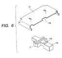
- Fig. 6 is a perspective view showing the cover 11 and the rod 17 used in the multidirectional switch in accordance with a third embodiment of the present invention.
- the rod 17 has the operating lever 17A.
- the operating lever 17A has a protrusion 17C integrally formed at the top thereof.
- the cover 11 has a cutout 11E at substantially the center of the front edge thereof. The cutout 11E is slightly wider than the protrusion 17C.
- the cover 11 and the rod 17 are assembled in the switch casing 15.
- the operating lever 17A of the rod 17 protrudes forward from the opening 15A of the casing 15.
- the rod 17 shifts rightward or leftward from the neutral position in the same manner as described in the first and second embodiments.
- the user can push the operating lever 17A in the push direction (i.e., back-and-forth direction) normal to the slide direction.
- the protrusion 17C of the rod 17 is guided into the cutout 11E of the cover 11.
- the pushing operation is feasible only in the neutral position where the protrusion 17C faces the cutout 11E.
- the front edge of the cover 11 other than the cutout 11E blocks the protrusion 17C when the rod 17 is depressed in the back-and-forth direction from a right or left position offset from the neutral position.
- the pushing operation is unfeasible.
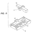
- Figs. 7 and 8 are perspective views showing modified arrangement of the rod 17 and the casing 15 in accordance with the third embodiment of the present invention.
- the operating lever 17A of the rod 17 has a protrusion 17D integrally formed at the bottom thereof.
- the opening 15A of the cover 11 has a cutout 15E at substantially the center thereof.
- the operating lever 17A of the rod 17 has a protrusion 17E integrally formed at the rear end thereof.
- a recess 15F is provided at a rear end wall of the casing 15 opposing the opening 15A.
- the modified arrangements shown in Figs. 7 and 8 function in the same manner as the arrangement shown in Fig. 6.
- the rod 17 has the protrusion 17C, 17D or 17E at an appropriate portion thereof.
- the cover 11 or the casing 15 has the cutout 11E or 15E or the recess 15F engageable with the protrusion 17C, 17D or 17E at the center thereof.
- the pushing operation is feasible only when the rod 17 is in the neutral position. However, it is possible to provide the cutout 11E or 15E or the recess 15F at an arbitrary portion so that the pushing operation is feasible at any intended position other than the neutral position.
- the third embodiment provides the rod 17 with the protrusion 17C, 17D or 17E.
- the cover 11 or the casing 15 has the cutout 11E, 15E or the recess 15F at the predetermined position.
- the pushing movement of the rod 17 is feasible only when the protrusion 17C, 17D or 17E of the rod 17 engages with and guided into the corresponding cutout 11E, 15E or recess 15F. Otherwise, the cover 11 or the casing 15 blocks the pushing movement of the rod 17.
- the third embodiment makes it possible to arbitrarily select the pushing position of the rod 17 according to the used conditions of the switch. Furthermore, the third embodiment surely prevents the rod 17 from being erroneously pushed during the slide operation.
- the present invention provides the multidirectional switch, wherein a protrusion (17C, 17D, 17E) is provided on the rod movable in the push direction and a recess (11E, 15E, 15F) is provided stationarily at a predetermined portion independent of the push movement of the rod, so that the protrusion of the rod can be guided and received by the recess only when the rod is depressed at a position where the protrusion faces the recess.
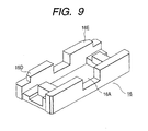
- Fig. 9 is a perspective view showing the slider 16 used in the multidirectional switch in accordance with a fourth embodiment of the present invention.
- Figs. 10A to 10D are plan views showing various operated conditions of the multidirectional switch under the condition the cover is removed off.
- the slider 16 is slidably accommodated in the casing 15.
- the rod 17 is slidable in the rod guide recess 16A of the slider 16.
- the left and right L-shaped springs 19 and 20 have the proximal portions 19A and 20A held by the spring holders 15B an 15C of the casing 15, respectively.
- the spring receive portions 16B and 16C of the slider 16 support the distal ends of the first arms 19B and 20B of the springs 19 and 20, respectively.
- the arm receive portions 11A and 11B of the cover 11 support the mesial portions of the first arms 19B and 20B, respectively.
- the spring push portions 18A and 18B of the push member 18 press the second arms 19D and 20D, respectively.
- the forth embodiment differs from the second embodiment in that the slider 16 has left and right spring push portions 16D and 16E provided at the rear end thereof.
- the user can move the operating lever 17A right from the neutral position shown in Fig. 10A.
- the spring receive portion 16C pushes the distal end (i.e., the bent portion 20C) of the first arm 20B of the right spring 20 when the slider 16 slides from the neutral position to the condition shown in Fig. 10B.
- the first arm 20B of the right spring 20 is thus elastically compressed by the spring receive portion 16C.
- the user can further move the operating lever 17A right from the Fig. 10B condition.
- the bent portion 20C formed at the distal end of the first arm 20B of the right spring 20 departs from the spring receive portion 16C of the slider 16.
- the spring push portion 16E formed at the rear end of the slider 16 pushes the mesial portion of the first arm 20B, as shown in Fig. 10C.
- the first arm 20B of the right spring 20 is elastically compressed by the spring push portion 16E.
- an increased operating force is necessary when the operating lever 17A slides rightward from the Fig. 10B condition to the Fig. 10C condition.
- the increase of the operating force occurs in response to the shift of the acting point of the pushing force acting from the rod 17 to the first arm 20B of the right spring 20. That is, the acting point of the pushing force transfers from the distal end (i.e., the bent portion 20C) to the mesial portion closer to the proximal portion 20A when the rod 17 further pushes the first arm 20B after exceeding the condition shown in Fig. 10B.
- the slider 16 accommodating the rod 17 returns to the neutral position shown in Fig. 10A by the elastic restoring force stored in the first arm 20B of the right spring 20.
- the slider 16 shifts from the Fig. 10C condition to the Fig. 10B condition.
- the mesial portion of the first arm 20B of the right spring 20 pushes the spring push portion 16E of the slider 16.
- the slider 16 further shifts from the Fig. 10B condition to the Fig. 10A condition.
- the distal portion (i.e., the bent portion 20C) of the first arm 20B pushes the spring receive portion 16C of the slider 16.
- the slider 16 returns the neutral position shown in Fig. 10A by the elastic restoring force of the right spring 20 that is larger in the beginning of the returning motion of the slider.
- the user can move the operating lever 17A left from the neutral position shown in Fig. 10A.
- the spring receive portion 16B of the slider 16 pushes the distal end (i.e., the bent portion 19C) of the first arm 19B of the left spring 19 in the earlier stage of the sliding movement of the slider 16.
- the spring push portion 16D of the slider 16 pushes the mesial portion of the first arm 19B in the later stage of the sliding movement of the slider 16.
- the first arm 19B is elastically compressed by the slider 16.
- the fourth embodiment provides the spring push portions 16D and 16E at the rear end of the slider 16.
- the contact points between the slider 16 and respective first arms 19B and 20B of the left and right springs 19 and 20 transfer from the distal ends (i.e., the bent portions 19C and 20C) to the mesial portions during the sliding movement of the slider 16.
- the fourth embodiment provides the operational feeling (i.e., operational load) varying during the sliding operation of the switch.
- Figs. 11A to 11C are plan views showing various operated conditions of a multidirectional switch in accordance with a fifth embodiment of the present invention, under the condition the cover is removed off.
- Fig. 12 is an exploded perspective view showing the multidirectional switch in accordance with the fifth embodiment.
- a slider 21 is slidably installed in the casing 15.
- the slider 21 has a rod guide recess 21A in which a rod 22 is slidable in the push direction.
- the rod 22 has an operating lever 22A.
- the second contact piece 7 is fixed to the lower surface of the rod 22.
- the fifth embodiment differs from the second embodiment in that substantially L-shaped springs 23 and 24 have proximal portions 23A and 24A held by cylindrical spring holders 21B and 21C integrally formed at left and right ends on the slider 21.
- the operating lever 22A of the rod 22 protrudes forward from the opening 15A of the casing 15.
- the second contact piece 7 fixed to the lower surface of the rod 22, resiliently slides on the surfaces of the first stationary contacts.
- the second contact piece 7 electrically connects the first stationary contacts 2B and 2C in the same manner as described in the second embodiment.
- the distal end of the first arm 23B of the left spring 23 departs from the spring receive portion 15G of the casing 15 in accordance with the rightward shift movement of the slider 21 accommodating the rod 22.
- the proximal portion 23A of the left spring 23 is held by the spring holder 21B of the holder 21.
- the arm receive portion 21D supports the mesial portion of the left spring 23.
- the spring receive portion 15H of the casing 15 supports the distal end of the first arm 24B of the right spring 24.
- the mesial portion of the first arm 24B departs from the arm receive portion 21E.
- the compressed right spring 24 resiliently pushes the slider 21 and the accommodated rod 22 back to the neutral position shown in Fig. 11A by the elastic restoring force stored in the first arm 24B of the right spring 24.
- the second contact piece 7 electrically disconnects the first stationary contacts 2B and 2C.
- the right spring 24 stores this elastic restoring force when the first arm 24B being supported by the spring receive portion 15H is elastically compressed.
- the user can move the operating lever 22A left from the neutral position shown in Fig. 11A.
- the distal end of the first arm 24B of the right spring 24 departs from the spring receive portion 15H.
- the arm receive portion 21E supports the mesial portion of the first arm 24B of the right spring 24.
- the mesial portion of the first arm 23B of the left spring 23 departs from the arm receive portion 21D of the slider 21.
- the distal end of the first arm 23B, supported by the spring receive portion 15G, is elastically compressed.
- the compressed left spring 23 resiliently pushes the slider 21 and the accommodated rod 22 back to the neutral position shown in Fig. 11A by the elastic restoring force stored in the first arm 23B of the left spring 23.
- the left spring 23 stores this elastic restoring force when the first arm 23B being supported by the spring receive portion 15G is elastically compressed.
- the user can depress the operating lever 22A in the push direction (i.e., back-and-forth direction) from the neutral position shown in Fig. 11A.
- spring push portions 22B and 22C of the rod 22 compress the distal ends of the second arms 23C and 24C of the left and right springs 23 and 24, respectively.
- the rod 22 slides rearward in the rod guide recess 21A, while the second arms 23C and 24C are elastically compressed.
- the proximal portions 23A and 24A of the L-shaped springs 23 and 24 are held by the spring holders 21B and 21C of the slider 21, respectively.
- the casing 15 has no spring holders at the left and right ends thereof. This reduces the back-and-forth size of the switch as well as downsizes the switch.
- the springs 23 and 24 can be assembled, as a unit component, on the upper surface of the slider 21. This unit can be easily installed in the casing 15 while the spring receive portions 15G and 15H support the first arms 23B and 24B of the springs 23 and 24, respectively. This facilitates the assembling work of the two springs 23 and 24 and the slider 21 into the casing 15. As a result, the switch assembling work can be simplified.
- a boxlike casing (15) with an open top, has an opening (15A) partly formed on a front wall thereof and a plurality of stationary contacts (2A ⁇ 2C, 3A ⁇ 3B) provided on an inner bottom surface thereof.
- a slider (2) is installed in the casing and slidable in a predetermined slide direction.
- the slider has a rod guide portion (21A) provided at a predetermined portion thereof and spring holders (21B, 21C) and arm receive portions (21D, 21E) provided at left and right ends thereof.
- a rod (22) is installed in the rod guide portion and slidable in a push direction normal to the slide direction.
- the rod has an operating lever (22A) protruding forward from the opening of the casing and a push portion (22B, 22C) extending rearward. At least one elastic contact piece (7) is fixed to at least one of lower surfaces of the slider and the rod for electrically connecting or disconnecting the stationary contacts.
- Two L-shaped springs (23, 24) have proximal portions (23A, 24A) held by the spring holders (21B, 21C) of the slider movable in the slide direction.
- the two springs have first arms (23B, 24B) and second arms (23C, 24C).
- the first arms (23B, 24B) have distal ends supported by spring receive portions (15G, 15H) stationarily provided at a predetermined portion independent of the slide movement of the slider and mesial portions received by the arm receive portions (21D, 21E) of the slider. And, the second arms (23C, 24C) are pressed by the push portion (22B, 22C) of the rod movable in the push direction.
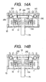
- Fig. 13 is a plan view showing a united spring used in the multidirectional switch in accordance with a sixth embodiment of the present invention.
- Figs. 14A and 14B are plan views showing an assembling method of the multidirectional switch of the sixth embodiment, under the condition the cover is removed off.
- the slider 16 is slidably installed in the casing 15.
- the rod 17 is accommodated in the slider 16 so as to be slidable in the push direction.
- the rod 17 has the operating lever 17A.
- the sixth embodiment differs from the second embodiment in that a spring 25 is a united spring consisting of two L-shaped springs connected at the distal ends of their second arms.
- the spring 25 has a thinned connecting portion 25A at the connecting point of the two L-shaped springs.
- the multidirectional switch of the sixth embodiment is assembled in the following manner.
- proximal portions 25B and 25C of the spring 25 are held by the spring holders 15B and 15C of the casing 15, respectively.
- the slider 16 and the rod 17 are assembled in such a manner that the operating lever 17A of the rod 17 protrudes forward from the opening 15A of the casing 15.
- the operating lever 17A is depressed.
- the push member 18 abuts the push portion 17B formed at the rear end of the rod 17.
- the spring 25 is broken at the thinned connecting portion 25A formed at the center thereof and separates into two L-shaped springs.
- the push member 18 presses the two separated arms 25D and 25E.
- the user can move the operating lever 17A in both the slide and push directions from the neutral position shown in Fig. 14A.
- the slider 16 and the push member 18 elastically compress the first arms and the second arms 25D and 25E of the L-shaped springs.
- the second contact piece 7 electrically connects the stationary contacts in the same manner as described in the second embodiment.
- the sixth embodiment provides the united spring 25 consisting of two arms 25D and 25E connected at the distal ends of their second arms 25D and 25E.
- the united spring 25 is separated into two independent L-shaped springs by pushing the rod 17.
- the total number of switch parts can be reduced.
- the united spring 25 is easy to handle when installed in the casing 15. This facilitates the assembling work of the switch.
- the present invention makes it possible to provide the multidirectional switch capable of reducing the number of the used springs, facilitating the assembling work of the switch, and reducing the cost.
Landscapes
- Switches With Compound Operations (AREA)
- Manufacture Of Switches (AREA)
- Push-Button Switches (AREA)
- Slide Switches (AREA)
- Rotary Switch, Piano Key Switch, And Lever Switch (AREA)
Claims (17)
- Commutateur multidirectionnel pouvant être manoeuvré à la fois dans des directions de glissement et de poussée, comportant un boítier (15) en forme de boíte présentant un dessus ouvert et une ouverture (15A) formée partiellement dans une paroi avant de ce boítier, plusieurs contacts fixes (2A-2C, 3A-3B) situés sur une surface intérieure du fond dudit boítier, et un curseur (16 ; 21) monté dans ledit boítier et pouvant glisser dans une direction prédéterminée de glissement,
et comportant en outre
une tige (17 ; 22) montée dans une partie (16A ; 21A) de guidage de tige située à une partie prédéterminée dudit curseur et pouvant glisser dans une direction de poussée normale à ladite direction de glissement, ladite tige ayant un levier de manoeuvre (17A ; 22A) faisant saillie vers l'avant de ladite ouverture dudit boítier et une partie de poussée (17B ; 22B, 22C) s'étendant vers l'arrière ;
au moins une pièce élastique de contact (6, 7) fixée à au moins l'une des surfaces inférieures dudit curseur et de ladite tige pour connecter ou déconnecter électriquement lesdits contacts fixes ; caractérisé par
deux ressorts (19, 20 ; 23, 24) en forme de L ayant des parties proximales (19A, 20A ; 23A, 24A) maintenues par des éléments de maintien de ressorts (15B, 15C ; 11C, 11D ; 21B, 21C), des premiers bras (19B, 20B, 23B, 24B) ayant des extrémités distales supportées par des parties (16B, 16C ; 15G, 15H) de réception de ressorts et des parties médianes reçues par des parties (11A, 11B ; 21D, 21E) de réception de bras, et des seconds bras (19D, 20D ; 23C, 24C) poussés par ladite partie de poussée (17B ; 22B, 22C) de ladite tige mobile dans ladite direction de poussée. - Commutateur multidirectionnel selon la revendication 1, dans lequel lesdits éléments de maintien de ressorts (15B, 15C) sont prévus fixement aux extrémités de gauche et de droite dans ledit boítier (15).
- Commutateur multidirectionnel selon la revendication 1, dans lequel lesdits éléments de maintien de ressorts (11C, 11D) sont prévus fixement à des parties de gauche et de droite sur une surface inférieure dudit capot (11).
- Commutateur multidirectionnel selon l'une quelconque des revendications 1 à 3, dans lequel lesdites parties de réception de ressorts (16B, 16C) sont prévues à des extrémités de gauche et de droite dudit curseur (16) mobile dans ladite direction de glissement.
- Commutateur multidirectionnel selon l'une quelconque des revendications 1 à 4, dans lequel lesdites parties de réception de bras (11A, 11B) sont prévues à des parties de gauche et de droite d'une surface inférieure dudit capot (11).
- Commutateur multidirectionnel selon la revendication 1, dans lequel lesdits éléments de maintien de ressorts (21B, 21C) sont prévus à des extrémités de gauche et de droite dudit curseur (21) mobile dans ladite direction de glissement.
- Commutateur multidirectionnel selon la revendication 1 ou 6, dans lequel lesdites parties de réception de bras (21D, 21E) sont prévues à des extrémités de gauche et de droite dudit curseur (21).
- Commutateur multidirectionnel selon l'une quelconque des revendications 1, 6 et 7, dans lequel lesdites parties de réception de ressorts (15G, 15H) sont prévues fixement dans ledit boítier (15) indépendamment du mouvement de glissement dudit curseur.
- Commutateur multidirectionnel selon l'une quelconque des revendications 1 à 8, comportant en outre un élément de poussée (18) interposé de façon coulissante entre ladite tige et lesdits deux ressorts, ledit élément de poussée ayant une face avant en appui sur ladite partie de poussée de ladite tige et des parties de poussée de ressorts (18A, 18B) poussant lesdits seconds bras desdits deux ressorts.
- Commutateur multidirectionnel selon l'une quelconque des revendications 1 à 9, dans lequel lesdits premiers bras desdits deux ressorts ont des parties coudées (19C, 20C) supportées par des parties correspondantes de réception de ressorts (16B, 16C) dudit curseur.
- Commutateur multidirectionnel selon l'une quelconque des revendications 1 à 10, dans lequel lesdits plusieurs contacts fixes comprennent des premiers contacts fixes (2A-2C) et des seconds contacts fixes (3A-3B) alignés en parallèle avec ladite direction de glissement, lesdits seconds contacts fixes s'alignant centralement sur ladite surface intérieure du fond du boítier, et lesdits premiers contacts fixes se positionnant plus près de ladite ouverture (15A) dudit boítier que lesdits seconds contacts fixes et, en outre, seule une pièce de contact (7) est placée exclusivement au-dessus desdits premiers contacts fixes et est fixée à la surface inférieure de ladite tige (17).
- Commutateur multidirectionnel selon l'une quelconque des revendications 1 à 11, dans lequel une saillie (17C, 17D, 17E) est prévue sur ladite tige mobile dans ladite direction de poussée et un évidement (11E, 15E, 15F) est prévu fixement dans une partie prédéterminée indépendante du mouvement de poussée de ladite tige, afin que ladite saillie de la tige puisse être guidée et reçue par ledit évidement, uniquement lorsque ladite tige est enfoncée dans une position où ladite saillie fait face audit évidement.
- Commutateur multidirectionnel selon la revendication 12, dans lequel ladite saillie (17C) est située sur une surface supérieure de ladite tige (17), et ledit évidement (11E) est situé sur un bord avant dudit capot (11).
- Commutateur multidirectionnel selon la revendication 12, dans lequel ladite saillie (17D) est située sur une surface inférieure de ladite tige (17), et ledit évidement (15E) est situé sur une paroi avant dudit boítier (15).
- Commutateur multidirectionnel selon la revendication 12, dans lequel ladite saillie (17E) est située sur une extrémité arrière de ladite tige (17), et ledit évidement (15F) est situé sur une paroi arrière dudit boítier (15).
- Commutateur multidirectionnel selon l'une quelconque des revendications 1 à 15, dans lequel ledit curseur (16) comporte des parties de poussée (16D, 16E) de ressorts à une extrémité arrière de ce curseur pour supporter des parties médianes desdits premiers bras (19B, 20B) desdits deux ressorts pendant le mouvement de glissement dudit curseur.
- Procédé d'assemblage du commutateur multidirectionnel défini dans l'une quelconque des revendications 1 à 16, comprenant les étapes dans lesquelles :on monte un ressort assemblé (25) dans ledit boítier, ledit ressort assemblé ayant une partie de liaison (25A) où lesdits deux ressorts en forme de L sont reliés solidairement aux extrémités distales desdits seconds bras ; eton pousse ladite partie de liaison (25A) dudit ressort assemblé à l'aide de ladite tige (17) afin de séparer ledit ressort assemblé en deux ressorts indépendants en forme de L.
Applications Claiming Priority (3)
| Application Number | Priority Date | Filing Date | Title |
|---|---|---|---|
| JP190839/97 | 1997-07-16 | ||
| JP19083997 | 1997-07-16 | ||
| JP19083997A JP3911774B2 (ja) | 1997-07-16 | 1997-07-16 | プッシュ機構付スライドスイッチ及びその組立て方法 |
Publications (3)
| Publication Number | Publication Date |
|---|---|
| EP0892418A2 EP0892418A2 (fr) | 1999-01-20 |
| EP0892418A3 EP0892418A3 (fr) | 1999-06-16 |
| EP0892418B1 true EP0892418B1 (fr) | 2005-06-15 |
Family
ID=16264634
Family Applications (1)
| Application Number | Title | Priority Date | Filing Date |
|---|---|---|---|
| EP98112491A Expired - Lifetime EP0892418B1 (fr) | 1997-07-16 | 1998-07-06 | Interrupteur manoeuvrable comme coulisseau que comme bouton poussoir et méthode d'assemblage |
Country Status (5)
| Country | Link |
|---|---|
| US (1) | US5969309A (fr) |
| EP (1) | EP0892418B1 (fr) |
| JP (1) | JP3911774B2 (fr) |
| CN (1) | CN1100334C (fr) |
| DE (1) | DE69830545T2 (fr) |
Families Citing this family (24)
| Publication number | Priority date | Publication date | Assignee | Title |
|---|---|---|---|---|
| DE59915250D1 (de) * | 1999-06-16 | 2011-04-07 | Phonak Ag | Hinterohr-hörgerät |
| JP4370042B2 (ja) * | 2000-05-12 | 2009-11-25 | アルプス電気株式会社 | 操作装置 |
| US20030221267A1 (en) * | 2002-05-30 | 2003-12-04 | The Procter & Gamble Co. | Electric toothbrushes and packages containing same |
| CN100384388C (zh) | 2002-05-30 | 2008-04-30 | 丘奇和德怀特有限公司 | 电动牙刷及包含电动牙刷的包装盒 |
| TWM300861U (en) * | 2006-03-20 | 2006-11-11 | Hon Hai Prec Ind Co Ltd | Slide switch |
| JP4730171B2 (ja) * | 2006-03-30 | 2011-07-20 | ミツミ電機株式会社 | プッシュ・スライドスイッチ |
| FR2899995B1 (fr) * | 2006-04-12 | 2008-07-04 | Bosch Rexroth D S I Soc Par Ac | Dispositif de controle rotatif pour une telecommande d'engin mobile, en particulier engin de travaux publics, engin agricole ou de manutention |
| CN2916893Y (zh) * | 2006-07-03 | 2007-06-27 | 富士康(昆山)电脑接插件有限公司 | 开关 |
| JP4837504B2 (ja) * | 2006-09-13 | 2011-12-14 | 富士通株式会社 | スイッチ用操作片ユニットおよび電子機器 |
| JP4857183B2 (ja) * | 2007-05-10 | 2012-01-18 | アルプス電気株式会社 | 複合操作型スイッチ装置 |
| JP4531793B2 (ja) * | 2007-06-11 | 2010-08-25 | ホシデン株式会社 | 複合操作型入力装置 |
| JP4932658B2 (ja) * | 2007-10-01 | 2012-05-16 | アルプス電気株式会社 | プッシュ機構付きスライド操作型電気部品 |
| CN101656162B (zh) * | 2008-08-20 | 2011-02-02 | 鸿富锦精密工业(深圳)有限公司 | 按键结构 |
| CN101740244A (zh) * | 2008-11-25 | 2010-06-16 | 深圳富泰宏精密工业有限公司 | 侧键组件及具有该侧键组件的便携式电子装置 |
| TWI382436B (zh) * | 2009-09-28 | 2013-01-11 | Forward Electronics Co Ltd | Both sliding and central press the switch |
| FR2954576B1 (fr) * | 2009-12-18 | 2012-12-21 | Somfy Sas | Dispositif de commande et installation domotique comprenant un tel dispositif |
| CN102169774A (zh) * | 2010-11-04 | 2011-08-31 | 无锡大星电子有限公司 | 双向开关装置 |
| US8586889B2 (en) | 2011-04-12 | 2013-11-19 | Amphenol Corporation | Multiposition switch |
| US9972459B1 (en) | 2013-09-09 | 2018-05-15 | Apple Inc. | Tactile switch assembly in an electronic device |
| US9691570B1 (en) | 2013-10-28 | 2017-06-27 | Apple Inc. | Modular tactile switch |
| US10109432B1 (en) | 2014-06-16 | 2018-10-23 | Apple Inc. | Switch assemblies |
| US10707032B1 (en) | 2016-12-02 | 2020-07-07 | Apple Inc. | Electronic device having travel-magnifying input/output structure |
| CN108693458B (zh) * | 2017-04-12 | 2021-01-26 | 环旭电子股份有限公司 | 用于芯片的测试插座 |
| CN110394950A (zh) * | 2019-09-02 | 2019-11-01 | 李素燕 | 一种用于片材状产品生产的注塑模具 |
Family Cites Families (11)
| Publication number | Priority date | Publication date | Assignee | Title |
|---|---|---|---|---|
| US2725432A (en) * | 1953-05-25 | 1955-11-29 | Gen Motors Corp | Switch |
| CA1066296A (fr) * | 1975-05-29 | 1979-11-13 | Ethyl Corporation | Preparation de pyrryl-2-acetonitriles |
| US4319100A (en) * | 1980-06-13 | 1982-03-09 | Amf Incorporated | Dual in-line programming slide switch |
| DE8320066U1 (de) * | 1983-07-12 | 1983-12-01 | Siemens AG, 1000 Berlin und 8000 München | Schiebeschalter |
| IT213976Z2 (it) * | 1988-06-23 | 1990-03-05 | Cge Spa | Struttura di contatti elettrici nella quale la forza assiale di azionamento e' solo una piccola frazione della forza esercitata sui contatti. |
| US5051552A (en) * | 1990-07-16 | 1991-09-24 | Ilinois Tool Works Inc. | Slide selector switch mechanism |
| US5120922A (en) * | 1991-02-22 | 1992-06-09 | Augat Inc. | Momentary pushbutton slide switch |
| FR2674041B1 (fr) * | 1991-03-15 | 1993-12-10 | Wabco Westinghouse | Dispositif de rappel en un point central. |
| JPH05217464A (ja) * | 1992-02-04 | 1993-08-27 | Shinmei Denki Kk | プッシュ機構付きスライドスイッチ |
| JPH0743901Y2 (ja) * | 1992-02-06 | 1995-10-09 | 東洋電装株式会社 | スイッチ |
| US5315079A (en) * | 1993-01-04 | 1994-05-24 | Illinois Tool Works Inc. | PCB mounted 6PDT slide switch |
-
1997
- 1997-07-16 JP JP19083997A patent/JP3911774B2/ja not_active Expired - Fee Related
-
1998
- 1998-07-06 DE DE69830545T patent/DE69830545T2/de not_active Expired - Fee Related
- 1998-07-06 EP EP98112491A patent/EP0892418B1/fr not_active Expired - Lifetime
- 1998-07-06 US US09/109,764 patent/US5969309A/en not_active Expired - Fee Related
- 1998-07-16 CN CN98116318A patent/CN1100334C/zh not_active Expired - Fee Related
Also Published As
| Publication number | Publication date |
|---|---|
| CN1205532A (zh) | 1999-01-20 |
| DE69830545T2 (de) | 2006-05-11 |
| EP0892418A2 (fr) | 1999-01-20 |
| DE69830545D1 (de) | 2005-07-21 |
| CN1100334C (zh) | 2003-01-29 |
| JP3911774B2 (ja) | 2007-05-09 |
| JPH1140003A (ja) | 1999-02-12 |
| US5969309A (en) | 1999-10-19 |
| EP0892418A3 (fr) | 1999-06-16 |
Similar Documents
| Publication | Publication Date | Title |
|---|---|---|
| EP0892418B1 (fr) | Interrupteur manoeuvrable comme coulisseau que comme bouton poussoir et méthode d'assemblage | |
| US6719577B2 (en) | Card connector | |
| EP1863047B1 (fr) | Interrupteur à coulisse | |
| JP2002150885A (ja) | レバースイッチ | |
| JP3793290B2 (ja) | 複合操作型電気部品 | |
| US6150624A (en) | Keyswitch device | |
| JP2005108570A (ja) | 複合操作型スイッチ装置 | |
| US4692573A (en) | Interlock push-push switch device | |
| KR100461682B1 (ko) | 슬라이더 작동 스위치 | |
| US5187335A (en) | Switch with interlocked operators | |
| JP2009134950A (ja) | プッシュスイッチ付きスライドスイッチ | |
| EP0024922B1 (fr) | Interrupteurs à action brusque | |
| US6965087B2 (en) | Electric switch | |
| EP1049121A2 (fr) | Interrupteur à curseur | |
| JP3882251B2 (ja) | プッシュ機構付スライドスイッチ | |
| CN224177262U (zh) | 开关 | |
| KR0136721Y1 (ko) | 전자제품의 전원스위치 동작장치 | |
| KR200154988Y1 (ko) | 다용도 누름버튼 | |
| JP2589914Y2 (ja) | スイッチ | |
| CN101447356A (zh) | 带有两级按压开关的滑动移位接触开关 | |
| WO2000010183A1 (fr) | Mecanisme de commande | |
| JP4619196B2 (ja) | 押圧スイッチ付き摺動式電子部品 | |
| JP2606927Y2 (ja) | スイッチ装置 | |
| KR100564029B1 (ko) | 슬라이드식 줌스위치 | |
| KR200353805Y1 (ko) | 가압식 줌스위치 |
Legal Events
| Date | Code | Title | Description |
|---|---|---|---|
| PUAI | Public reference made under article 153(3) epc to a published international application that has entered the european phase |
Free format text: ORIGINAL CODE: 0009012 |
|
| 17P | Request for examination filed |
Effective date: 19980706 |
|
| AK | Designated contracting states |
Kind code of ref document: A2 Designated state(s): DE FR GB |
|
| AX | Request for extension of the european patent |
Free format text: AL;LT;LV;MK;RO;SI |
|
| PUAL | Search report despatched |
Free format text: ORIGINAL CODE: 0009013 |
|
| AK | Designated contracting states |
Kind code of ref document: A3 Designated state(s): AT BE CH CY DE DK ES FI FR GB GR IE IT LI LU MC NL PT SE |
|
| AX | Request for extension of the european patent |
Free format text: AL;LT;LV;MK;RO;SI |
|
| AKX | Designation fees paid |
Free format text: DE FR GB |
|
| GRAP | Despatch of communication of intention to grant a patent |
Free format text: ORIGINAL CODE: EPIDOSNIGR1 |
|
| GRAS | Grant fee paid |
Free format text: ORIGINAL CODE: EPIDOSNIGR3 |
|
| GRAA | (expected) grant |
Free format text: ORIGINAL CODE: 0009210 |
|
| AK | Designated contracting states |
Kind code of ref document: B1 Designated state(s): DE FR GB |
|
| REG | Reference to a national code |
Ref country code: GB Ref legal event code: FG4D |
|
| REF | Corresponds to: |
Ref document number: 69830545 Country of ref document: DE Date of ref document: 20050721 Kind code of ref document: P |
|
| PG25 | Lapsed in a contracting state [announced via postgrant information from national office to epo] |
Ref country code: GB Free format text: LAPSE BECAUSE OF NON-PAYMENT OF DUE FEES Effective date: 20050915 |
|
| PLBE | No opposition filed within time limit |
Free format text: ORIGINAL CODE: 0009261 |
|
| STAA | Information on the status of an ep patent application or granted ep patent |
Free format text: STATUS: NO OPPOSITION FILED WITHIN TIME LIMIT |
|
| GBPC | Gb: european patent ceased through non-payment of renewal fee |
Effective date: 20050915 |
|
| 26N | No opposition filed |
Effective date: 20060316 |
|
| EN | Fr: translation not filed | ||
| PG25 | Lapsed in a contracting state [announced via postgrant information from national office to epo] |
Ref country code: FR Free format text: LAPSE BECAUSE OF FAILURE TO SUBMIT A TRANSLATION OF THE DESCRIPTION OR TO PAY THE FEE WITHIN THE PRESCRIBED TIME-LIMIT Effective date: 20060811 |
|
| PG25 | Lapsed in a contracting state [announced via postgrant information from national office to epo] |
Ref country code: FR Free format text: LAPSE BECAUSE OF FAILURE TO SUBMIT A TRANSLATION OF THE DESCRIPTION OR TO PAY THE FEE WITHIN THE PRESCRIBED TIME-LIMIT Effective date: 20050731 |
|
| PGFP | Annual fee paid to national office [announced via postgrant information from national office to epo] |
Ref country code: DE Payment date: 20080711 Year of fee payment: 11 |
|
| PG25 | Lapsed in a contracting state [announced via postgrant information from national office to epo] |
Ref country code: FR Free format text: LAPSE BECAUSE OF FAILURE TO SUBMIT A TRANSLATION OF THE DESCRIPTION OR TO PAY THE FEE WITHIN THE PRESCRIBED TIME-LIMIT Effective date: 20050615 |
|
| PG25 | Lapsed in a contracting state [announced via postgrant information from national office to epo] |
Ref country code: DE Free format text: LAPSE BECAUSE OF NON-PAYMENT OF DUE FEES Effective date: 20100202 |