EP0892460A1 - Réflecteur d'antenne attaché par son bord et à faible volume de stockage - Google Patents
Réflecteur d'antenne attaché par son bord et à faible volume de stockage Download PDFInfo
- Publication number
- EP0892460A1 EP0892460A1 EP98305401A EP98305401A EP0892460A1 EP 0892460 A1 EP0892460 A1 EP 0892460A1 EP 98305401 A EP98305401 A EP 98305401A EP 98305401 A EP98305401 A EP 98305401A EP 0892460 A1 EP0892460 A1 EP 0892460A1
- Authority
- EP
- European Patent Office
- Prior art keywords
- reflector
- ribs
- spacecraft
- main rib
- rib
- Prior art date
- Legal status (The legal status is an assumption and is not a legal conclusion. Google has not performed a legal analysis and makes no representation as to the accuracy of the status listed.)
- Granted
Links
Images



Classifications
-
- H—ELECTRICITY
- H01—ELECTRIC ELEMENTS
- H01Q—ANTENNAS, i.e. RADIO AERIALS
- H01Q1/00—Details of, or arrangements associated with, antennas
- H01Q1/27—Adaptation for use in or on movable bodies
- H01Q1/28—Adaptation for use in or on aircraft, missiles, satellites, or balloons
- H01Q1/288—Satellite antennas
-
- H—ELECTRICITY
- H01—ELECTRIC ELEMENTS
- H01Q—ANTENNAS, i.e. RADIO AERIALS
- H01Q15/00—Devices for reflection, refraction, diffraction or polarisation of waves radiated from an antenna, e.g. quasi-optical devices
- H01Q15/14—Reflecting surfaces; Equivalent structures
- H01Q15/16—Reflecting surfaces; Equivalent structures curved in two dimensions [2D], e.g. paraboloidal
- H01Q15/161—Collapsible reflectors
Definitions
- the present invention relates to deployable satellite reflector antennas, and more particularly, to an edge-supported collapsible mesh type reflector antenna of the type launched and sustained in space.
- High gain antenna reflectors have been deployed into space for several decades.
- the configurations of such reflectors have varied widely as material science has developed and as the sophistication of technology and scientific needs have increased.
- rib and mesh designs have been supplied and utilized.
- a network of tensioned radial and circumferential chords divides the mesh into substantially flat facets.
- the effect on the reflector performance caused by the difference in shape between these flat facets and the true parabolic surface is referred to as the faceting error.
- Prior art mesh reflector designs require the use of numerous facets because the circumferential and angular spacing between the ribs and the mesh attachment locations are not optimized to minimize the faceting error.
- antenna designs typically include a center post about which the petals are configured, much like an umbrella configuration. This also affects the reflective quality of the resulting surface, because the center portion typically is the point of optimum reflectance, which is often blocked by the center post. Thus, it is desirable to have a structure that is deployable from a compact, stored position to an open dish-shaped position without center post blockage.
- GFRP graphite fiber reinforced, plastic materials
- antenna reflectors of the collapsible and foldable variety are of two design types.
- One type is a grid or mesh-type reflector that is folded like an umbrella.
- the other type includes foldable rigid and hinged petal members.
- Antennas of the second type are available in a variety of configurations, some of which are disadvantaged by the requirement for an excessive number of joints and segment pieces which, owing to the particular folding and collapsing construction, are of different shape and size. Also, the larger the number of hinges and segments, the more complex will be the deployment mechanism and its operation. Any added weight also is a disadvantage relative to a satellite system.
- the number of ribs used determines the width of each mesh singly-curved gore.
- more ribs result in more and narrower mesh gores, with each narrower gore being a better approximation of the ideal paraboloid shaped gore.
- an object of the present invention to provide an improved umbrella-type reflector having a low stowage profile. It is also an object of the present invention to provide a mesh-type, dish-shaped reflector which is an improvement over known mesh-type reflectors.
- a mesh-type umbrella-like reflector for use on an orbiting spacecraft.
- the reflector has a contoured main rib and a plurality of contoured secondary ribs each connected to a hub assembly by a respective hinge such that activation of the hub assembly causes the reflector to move between collapsed and opened configurations.
- the mesh member is attached to the ribs.
- a deployment boom connects the main rib of the reflector to the spacecraft. The deployment boom is operable with the main rib and the spacecraft to move the reflector between a stowed configuration proximate the spacecraft and a deployed configuration outside the spacecraft.
- a feed assembly is connected to the spacecraft.
- the feed assembly is offset from and operable with the mesh member of the reflector when the reflector is in the opened and deployed configurations to receive and/or transmit radio frequency energy therefrom.
- the reflector stowed profile is sufficiently slim to permit the stowage of a reflector up to twenty-five meters in diameter attached to a full-sized spacecraft (via two or more clam-shell type deployable clamps) on one or more commercially available launch vehicles.
- Umbrella reflector assembly 10 includes a reflector 12 connected to a spacecraft 14 by a relatively stiff deployment boom 16.
- Reflector 12 is shown in Figure 1 in a deployed configuration and shown in dashed lines in a stowage configuration within a booster payload fairing 15.
- Reflector 12 may have a diameter ranging from six to twenty-five meters.
- Figure 1 shows a 15 X 12.3 meter reflector in a mid-sized booster fairing.
- Figure 1A illustrates reflector 12 in a stowed configuration within booster payload fairing 15.
- Booster payload fairing 15 shown in Figure 1A is a Long March III-B fairing.
- Reflector 12 includes a main rib 18 and a plurality of secondary ribs 20.
- Boom 16 connects main rib 18 to spacecraft 14.
- Main rib 18 has a torque box construction and contoured edges and is connected to boom 16 to provide an "edge-support" for reflector 12.
- Secondary ribs 20, which are described in more detail below, are of a light weight planer-truss construction and are contoured and tapered toward their outer edges.
- a mesh 22 which acts as a reflecting surface.
- Reflector 12 further includes a hub assembly 24. Hub assembly 24 is connected to main rib 18 and secondary ribs 20 and assists in moving the ribs between the deployed and stowed configurations.
- a feed assembly 26 cn spacecraft 14 is operable with reflector 12 to transmit and/or receive radio frequency (RF) energy therefrom. Feed assembly 26 is offset from the edge of reflector 12 thus avoiding self blockage by the feed assembly of the reflected antenna RF energy.
- RF radio frequency
- a first deployment actuator 28 connects a top end 30 of boom 16 to main rib 18.
- a second deployment actuator 32 connects a bottom end 34 of boom 16 to spacecraft 14.
- Deployment actuators 28 and 32 are preferably of the conventional viscous damped spring actuator type.
- a pair of secondary ribs 20a and 20b generally opposite of main rib 18 are spaced apart when stowed to permit the passage and nesting of boom 16 between them on the same plane and opposite to the main rib.
- rib 20a falls directly behind rib 20b due to symmetry and is not specifically shown in the Figure.
- the number of secondary ribs 20 is an even number such that the total number of ribs 18 and 20 (and thus the number of triangular reflector gore segments) is an odd number. Thus, none of secondary ribs 20 falls directly opposite main rib 18, where boom 16 stows.
- FIG 2 illustrates the connection of a rib such as secondary rib 20 to hub assembly 24.
- ribs 18 and 20 is connected by a single hinge to hub assembly 24.
- hinge 40 attaches secondary rib 20 to hub assembly 24.
- the hinges are designed to be zero-clearance (pre-loaded) hinges.
- the hinge construction shown is aimed at minimizing the center spacing between the hinges, and thus the diameter of hub assembly 24, while permitting rib assembly and disassembly.
- the small hub diameter (about 4% of the reflector diameter) permits stowage of reflector 12 in the often unused volume near the top 41 of booster payload fairing 15.
- the hinge axis orientations for each of the ribs are individually optimized to effect the tightest possible folding thus minimizing the width of reflector 12 where the reflector passes between spacecraft corner 42 and the booster payload fairing 15 without significantly compromising the width of the reflector in the orthogonal direction.
- the orthogonal direction is the direction perpendicular to the view shown in Figure 1.
- FIG. 3a illustrates reflector 12 in the stowed and launch configurations.
- a plurality of stowage clamps 46(a-c) hold reflector 12 to spacecraft 14.
- Stowage clamps 46(a-c) include pyrotechnic devices (e.g., bolt cutters or separation nuts) to lock and release the stowage clamps as will be explained later with reference to Figure 4.
- first deployment actuator 28 connect main rib 18 to boom 16.
- First deployment actuator 28 causes reflector 12 to move away from spacecraft 14 as shown in Figure 3b.
- second deployment actuator 32 connecting bottom end 34 of boom 16 to spacecraft 14 is activated.
- Second deployment actuator 32 causes reflector 12 to move up and around spacecraft 14 as showm in Figure 3c. As can be seen, this motion passes boom 16 through the upper stowage clamp 46a which is facilitated by the particular design of the clamp to be discussed in relationship to Figure 4.
- Figure 3d depicts reflector 12 in the operational deployed configuration.
- hub assembly 24 is activated to force ribs 18 and 20 open relative to hub assembly 24 as will be explained in greater detail with reference to Figure 5.
- reflector 12 is operational with offset feed assembly 26 to transmit and/or receive RF energy therefrom.
- a second reflector assembly 50 on spacecraft 14 may be employed for a different frequency band in addition to reflector 12.
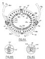
- FIG. 4 illustrates an exemplary stowage device 46.
- the stowage device 46 is double acting with both front half 52 and back half 54 deployable in order to permit passage of boom 16 through the stowage device during the second motion of deployment described above.
- Front half 52 and back half 54 includes respective arms 56(a-b) and 58(a-b).
- Arms 56(a-b) and 58(a-b) are pivotable about a respective hinge assembly 51(a-d) with an associated crushable/catcher fixture assembly 60 and 62.
- Arms 56a and 58a are connected by a separation bolt having a bolt cutter 64 and a bolt catcher 66. The separation bolt is releasably engaged to allow arms 56a and 58a to open.
- bolt cutter 64 which is pyrotechnically operated using small explosive charges to sever the separation bolt upon ground command.
- Other pyrotechnic devices such as separation nuts may be used alternatively to perform this function.
- Arms 56b and 58b are similarly arranged.
- Arms 56 and 58 include adjustable screws 53 having hemisperical heads which engage dry lubricated metallic washers with sperical indentations 55 bonded (or otherwise attached) to each of secondary ribs 20 and main rib 18. Additionally, at the stowage device locations, ribs 18 and 20 are spherically rotatably engaged to each other using pairs of male spherical protrusions 57 and dry lubricated female washers with sperical indentations 59 attached to the ribs via light weight stand offs (61a,b).
- Hub assembly 24 includes a hub 57.
- a shaft 68 and two stepper motors 70(a-b) are connected to hub member 67.
- Hub assembly 24 further includes a base plate 72.
- a motor strap 74 wraps around pullies 76(a-b) connected to base plate 72 and connects at its two ends to pullies mounted to respective stepper motors 70(a-b).
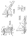
- base plate 72 restrains secondary rib 20 against deployment by engaging the secondary rib through a shear cone 77 shown in greater detail in Figure 6.
- Secondary rib 20 is connected to hub member 67 by hinge 40.
- a lower heavy GFRP strap 78 connects secondary rib 20 to base plate 72.
- a relatively flexible upper strap 80 connects secondary rib 20 to shaft 68 above hub 67.
- Deployment of reflector 12 is effected by activating either or both of stepper motors 70(a-b) operative with motor strap 74, pullies 76(a-b), and base plate 72 to redundantly slowly drive shaft 68 upwards through hub 67.
- stepper motors 70(a-b) operative with motor strap 74, pullies 76(a-b), and base plate 72 to redundantly slowly drive shaft 68 upwards through hub 67.
- upper strap 80 pulls on secondary rib 20 causing it to extend away from hub assembly 24 as shown in Figure 5b.
- base plate 72 is completely behind the theoretical reflector surface and reflector 12 is in the deployed configuration shown in Figures 1 and 5c.
- Hub assembly 24 is capable of slowly controlled (non-dynamic), reversible deployment in 1-G environment without off loading (except for main rib 18) initiated without irreversible pyrotechnic events. Hub assembly 24 incorporates all moving parts into a compact separately testable assembly, thus maximizing deployment reliability and testability.
- FIG. 7 illustrates the layout of mesh member 22 on reflector 12.
- Mesh member 22 is divided into a plurality of trapezoidal-shaped facets 82 by a network of pre-tensioned Kevlar or Vectran radial chords 84 and circumferential chords 86. Chords 84 and 86 are conscructed on the focus side (towards feed assembly 26) of mesh member 22.
- Mesh 22 is thus divided into substantially flat facets 82.
- Mesh 22 is attached to ribs 18 and 20 only at corners 88 of facets 82. In short, mesh 22 is attached at radial attach points running along ribs 18 and 20.
- the effect on the performance of reflector 12 caused by the difference in shape between flat faces 82 and the true parabolic surface is referred to as the faceting error.
- the number of reflector ribs is chosen to limit the faceting error to an acceptable value.
- the faceting error resulting from a given number of ribs, or conversely, the number of ribs required to limit the faceting error to a given level is further optimized by three characteristics.
- the circumferential spacing between adjacent ribs 18 and 20 is varied across reflector 12.
- the vertex of the reflector is near the outer end of main rib 18 where it connects to first deployment actuator 23.
- the curvature of reflector 12 is the highest nearest the vertex.
- main rib 18 and adjacent secondary ribs 20 have a higher curvature than secondary ribs 20 farthest away from the vertex.
- Pair of secondary ribs 20 (a-b) opposite from main rib 18 have the lowest curvature.
- the circumferential spacing between the rib tips is reduced for the ribs nearest the vertex and gradually increases as the ribs extend to the cpposite end near ribs 20(a,b).
- secondary ribs 20(a-b) have the largest angular spacing and secondary ribs 20 adjacent on each side of main rib 18 are spaced from the main rib with the smallest circumferential spacing.
- the purpose of using uneven spacing between ribs 18 and 20 is to approximately equalize the normal distance between the outermost circumferential chords and the parabolic surface.
- the number of radial attachment points of mesh member 22 along ribs 18 and 20 are appropriately selected. For instance, it can be shown that if the objective is to minimize the total number of radial attachment points then the optimum number of radial attachment points is equal to the number of ribs divided by ( ⁇ multiplied by the square root of 2) : N R ⁇ 2 However, because the number of radial attachment points has significantly less impact on cost and weight of reflector 12 than the number of ribs, the number of radial attachment points is selected to be at least equal to the number of ribs divided by ⁇ .
- the radial spacing between the radial attach points along ribs 18 and 20 decreases as the circumference of reflector 12 increases. Because the faceting error is proportional to the area of the facet multiplied by the square of the maximum distance from the facet to the parabolic surface and by the power density of the feed illumination (B), optimum spacing between the radial attach points is achieved when the quantity ( W * L * (W 2 + L 2 ) 2 * B) is approximately equal for all facets. W and L are the average width and length of a facet, respectively. rhe phase relationships between the various radiating feed elements of feed assembly 26 are also optimized to minimize the faceting errors.
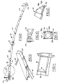
- Main rib 18 consists of two portions. Namely, inner main rib 90, which starts out as part of hub assembly 24, and outer main rib 92. Ribs 90 and 92 each have a bonded built-up box beam cross-section and is fabricated primarily from GFRP plates, angle members, and channel members. Outer main rib 92, including its integral end fitting 94 is fabricated primarily from only two different thickness plates 95 and 96, one channel member 97, and four different size angle members 98(a-d). The curved reflector contour of outer main rib 90 is provided by numerically controlled (N/C) machining of the side plates to the required profile. Tooling holes 99 are provided in the side plates and near the ends of each channel and angle to aid in assembling main rib 18.
- N/C numerically controlled
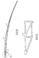
- Secondary rib 20 consists of an inner secondary rib 110, which is a part of hub assembly 24, and an outer secondary rib 112. Because there is a relatively large number of secondary ribs, they account for the largest single weight item of reflector 12. It is therefore important to design the secondary ribs with a low cost, lightweight structure.
- secondary rib 20 has a planar truss (frame) shape N/C machined (or waterjet cut) from a large honeycomb sandwich plate.
- the sandwich plate has thin GFRP facesheets and a non-metallic core made of Nomex, Corex or Kevlar.
- outer secondary rib 112 is made out of one to three segments spliced together using small bonded GFRP doubler plates with the aid of simple flat tooling with indexing tooling holes/pins. This approach minimizes fabrication time and tooling cost, permits maximum flexibility for rib weight optimization, and provides an accurate contour shape.
- the absence of mechanical joints (except for the one preloaded hinge per rib) and the minimum number of bonded joints makes for a highly predictable structural and thermo-structural behavior for reflector 12.
- Stepper motors 70(a-b) account for more than half the weight of the tiny amount of metallic materials used, with the remainder of the weight confined to small components such as fasteners, monoballs, bushings, etc., which have no detrimental effect on thermal distortion.
- the choice of the type of graphite fiber used for secondary ribs 20 is important. Because the design is generally stiffness and/or stability driven, the cost per unit stiffness is the most significant parameter in order to minimize cost.
- the specific compressive stiffness is the preferred measure for stiffness and stability efficiency.
- Ultra-high modulus Graphite fibres of Toray Industries, Inc. designated as M55J. have a low cost per unit stiffness.
- Ultra-high modulus Graphite fibres of Nippon Graphite Fibre corporation designated as XN70 have a high specific compressive stiffness. Accordingly, M55J is preferably used for the construction of secondary ribs 20 because it has a specific compressive stiffness of 85% of that of XN70 at less than half the cost per pound, as well as significantly higher strength.
- the present invention provides a reflector assembly having maximized deployment reliability and performance with minimum cost.
- High surface accuracy resulting in high reflector performance is enhanced by two general features. First, enhanced deployment repeatability and second, minimum thermal distortion.
- Deployment repeatability is enhanced by two specific features. First, pre-loaded monoballs or ball bearings 41 are used to form the rib/hub hinges 40. Hinges 40 are further pre-loaded by use of two sets of deployment straps 78 and 80 which results in a repeatable hinge contact point regardless of the magnitude of the tension in either strap. This enhances repeatability by eliminating the effect of hinge sloppiness on the deployed shape.
- Thermal distortion is minimized by three specific techniques. First, the choice of the composite lay-ups is selected consistent with the type of graphite fiber used. The result is very low CTEs in the range of +.05 to -.20 ppm/degree F. The addition of minor amounts of adhesive, foam fill, and/or metallic fasteners/inserts, result in effective CTEs in the range of +.1 to -.2ppm/degree F, which in turn minimizes thermal distortion.
- thermal blankets are positioned around ribs 18 and 20 and boom 16.
- the thermal blankets reduce the gradient through the thickness and across the depth of the ribs and the boom further reducing the thermal distortion.
- the blankets which are designed to be fabricated using pressure sensitive adhesive rather than Velcro tape, serve the additional function of protecting mesh member 22 from possible snagging on exposed honeycomb core edges or fastener heads.
- the effect of the relatively high mesh CTEs is rendered negligible by the use of an extremely low stiffness tricot knit.
- the effect of the moderately low CTE and moisture sensitivity of the Kevlar mesh retension chords is also rendered negligible by the use of soft springs in series with each of these chords.
- reflector 12 is deployable in one-G without the need for off-loading ground support equipment (GSE). Only main rib 18 is off-loaded using dead weights and pulleys hanging from a crane or by using a helium-filled balloon. This avoids the expense, facility limitation, and errors and uncertainties induced by a huge multitrack off-loader system.
- GSE ground support equipment
- the high capability deployment system required to accomplish the task in 1-G will provide a high deployment margin in zero-G.
- the 1-G deployability is made possible by the highly efficient rib structural design (high stiffness, super lightweight trussed graphite honeycomb) and the ultra lightweight mesh and mesh restraint chords utilized.
- soft tooling integration concept produces high surface accuracy at low cost.
- the soft tooling integration concept eliminates the cost and facility requirements associated with large tooling required for typical spacecraft reflectors of the prior art.
- the soft tooling integration concept involves several steps labeled A-G in the following paragraphs.
- a 40' X 50' (12.3 meter projected aperture) engineering development model reflector utilizing the teachings of the present invention was designed, built and tested. Photogrammetric surface measurements were taken showing that the reflector met the as-built RMS goal of 1mm. Three successful deployment demonstrations were performed (two prior to vibration testing and one post-vibration testing). Moreover, a protoflight level sine vibration test was performed with the reflector supported on a spacecraft simulation fixture and successfully, completed as indicated by a post-test functional deployment and surface measurement demonstration.
Landscapes
- Physics & Mathematics (AREA)
- Engineering & Computer Science (AREA)
- Astronomy & Astrophysics (AREA)
- General Physics & Mathematics (AREA)
- Remote Sensing (AREA)
- Electromagnetism (AREA)
- Aviation & Aerospace Engineering (AREA)
- Aerials With Secondary Devices (AREA)
- Details Of Aerials (AREA)
Applications Claiming Priority (2)
| Application Number | Priority Date | Filing Date | Title |
|---|---|---|---|
| US888762 | 1997-07-07 | ||
| US08/888,762 US5963182A (en) | 1997-07-07 | 1997-07-07 | Edge-supported umbrella reflector with low stowage profile |
Publications (2)
| Publication Number | Publication Date |
|---|---|
| EP0892460A1 true EP0892460A1 (fr) | 1999-01-20 |
| EP0892460B1 EP0892460B1 (fr) | 2001-10-17 |
Family
ID=25393836
Family Applications (1)
| Application Number | Title | Priority Date | Filing Date |
|---|---|---|---|
| EP98305401A Expired - Lifetime EP0892460B1 (fr) | 1997-07-07 | 1998-07-07 | Réflecteur d'antenne attaché par son bord et à faible volume de stockage |
Country Status (4)
| Country | Link |
|---|---|
| US (1) | US5963182A (fr) |
| EP (1) | EP0892460B1 (fr) |
| JP (1) | JP3021421B2 (fr) |
| CA (1) | CA2242061C (fr) |
Cited By (8)
| Publication number | Priority date | Publication date | Assignee | Title |
|---|---|---|---|---|
| US6313811B1 (en) | 1999-06-11 | 2001-11-06 | Harris Corporation | Lightweight, compactly deployable support structure |
| US6618025B2 (en) | 1999-06-11 | 2003-09-09 | Harris Corporation | Lightweight, compactly deployable support structure with telescoping members |
| FR2841047A1 (fr) * | 2002-10-09 | 2003-12-19 | Agence Spatiale Europeenne | Reflecteur d'antenne pliable et depliable, notamment pour une antenne de grande envergure destinee a des applications de telecommunications spatiales |
| US7598922B2 (en) | 2004-04-08 | 2009-10-06 | Astrium Limited | Deployable booms |
| CN107959124A (zh) * | 2017-11-22 | 2018-04-24 | 西安航天恒星科技实业(集团)公司 | 展开式轻型网状天线 |
| WO2019094239A1 (fr) * | 2017-11-13 | 2019-05-16 | Northrop Grumman Systems Corporation | Réflecteur déployable à grande ouverture déployé par une flèche télescopique |
| CN110277650A (zh) * | 2019-07-10 | 2019-09-24 | 厦门莱慧贸易有限公司 | 一种用于户外作业的便携式卫星天线 |
| CN110534913A (zh) * | 2019-08-13 | 2019-12-03 | 西安空间无线电技术研究所 | 一种折叠收拢固面反射器 |
Families Citing this family (46)
| Publication number | Priority date | Publication date | Assignee | Title |
|---|---|---|---|---|
| US6384800B1 (en) * | 1999-07-24 | 2002-05-07 | Hughes Electronics Corp. | Mesh tensioning, retention and management systems for large deployable reflectors |
| US6340956B1 (en) | 1999-11-12 | 2002-01-22 | Leland H. Bowen | Collapsible impulse radiating antenna |
| US6353421B1 (en) * | 2000-09-14 | 2002-03-05 | Ball Aerospace And Technologies Corp. | Deployment of an ellectronically scanned reflector |
| US6424314B1 (en) * | 2001-05-16 | 2002-07-23 | Space Systems/Loral, Inc. | Four axis boom for mounting reflector on satellite |
| US7595769B2 (en) * | 2006-02-28 | 2009-09-29 | The Boeing Company | Arbitrarily shaped deployable mesh reflectors |
| US7570226B2 (en) * | 2006-02-28 | 2009-08-04 | The Boeing Company | Method and apparatus for grating lobe control in faceted mesh reflectors |
| USD558758S1 (en) | 2007-01-05 | 2008-01-01 | Apple Inc. | Electronic device |
| US20090002257A1 (en) * | 2007-05-22 | 2009-01-01 | Thin Red Line Aerospace Ltd. | Precision flexible support structure |
| US8314748B2 (en) * | 2007-06-26 | 2012-11-20 | The Aerospace Corporation | Heptagonal antenna array |
| USD602486S1 (en) | 2007-08-31 | 2009-10-20 | Apple Inc. | Electronic device |
| USD957385S1 (en) | 2007-08-31 | 2022-07-12 | Apple Inc. | Electronic device |
| USD615083S1 (en) | 2008-04-07 | 2010-05-04 | Apple Inc. | Electronic device |
| USD627777S1 (en) | 2010-01-06 | 2010-11-23 | Apple Inc. | Portable display device |
| USD627778S1 (en) | 2010-04-19 | 2010-11-23 | Apple Inc. | Electronic device |
| USD864949S1 (en) | 2010-04-19 | 2019-10-29 | Apple Inc. | Electronic device |
| USD683730S1 (en) | 2010-07-08 | 2013-06-04 | Apple Inc. | Portable display device with graphical user interface |
| USD681630S1 (en) | 2010-07-08 | 2013-05-07 | Apple Inc. | Portable display device with graphical user interface |
| USD642563S1 (en) | 2010-08-16 | 2011-08-02 | Apple Inc. | Electronic device |
| US8789796B2 (en) * | 2010-09-16 | 2014-07-29 | Space Systems/Loral, Llc | High capacity broadband satellite |
| USD670692S1 (en) | 2011-01-07 | 2012-11-13 | Apple Inc. | Portable display device |
| USD669468S1 (en) | 2011-01-07 | 2012-10-23 | Apple Inc. | Portable display device |
| EP4462601A3 (fr) | 2010-12-15 | 2025-02-19 | Planet Labs PBC | Système d'antenne intégré pour l'imagerie de microsatellites |
| IL220220A (en) | 2011-06-08 | 2017-01-31 | Heliofocus Ltd | Spatial structure assemblies |
| US9248922B1 (en) | 2011-08-23 | 2016-02-02 | Space Systems/Loral, Llc | Reflector deployment techniques for satellites |
| US9004409B1 (en) | 2011-08-23 | 2015-04-14 | Space Systems/Loral, Llc | Extendable antenna reflector deployment techniques |
| CN102765490B (zh) * | 2012-08-03 | 2014-08-06 | 西安电子科技大学 | 空间绳系可展开遮蔽面系统 |
| USD681632S1 (en) | 2012-08-11 | 2013-05-07 | Apple Inc. | Electronic device |
| US9337544B2 (en) * | 2013-01-07 | 2016-05-10 | Lockheed Martin Corporation | Configurable backing structure for a reflector antenna and corrective synthesis for mechanical adjustment thereof |
| JP6248651B2 (ja) * | 2014-01-28 | 2017-12-20 | 日本電気株式会社 | 電波監視装置 |
| CN103904407B (zh) * | 2014-04-25 | 2015-10-21 | 哈尔滨工业大学 | 一种肋板式充气展开抛物面天线的电机驱动展开控制机构 |
| CN104591004B (zh) * | 2015-01-27 | 2016-08-24 | 中国科学院国家天文台 | Fast反射面吊装与六索拖舱入港无干涉运行的方法及装置 |
| US10053240B1 (en) * | 2016-05-20 | 2018-08-21 | Space Systems/Loral, Llc | Stowage, deployment and positioning of rigid antenna reflectors on a spacecraft |
| CN106773456A (zh) * | 2016-12-09 | 2017-05-31 | 中国科学院长春光学精密机械与物理研究所 | 一种可展开遮光罩装置 |
| CN109088149A (zh) * | 2018-07-25 | 2018-12-25 | 中国空间技术研究院 | 一种大型天线系统折叠装星方法 |
| US10418712B1 (en) | 2018-11-05 | 2019-09-17 | Eagle Technology, Llc | Folded optics mesh hoop column deployable reflector system |
| US10811759B2 (en) | 2018-11-13 | 2020-10-20 | Eagle Technology, Llc | Mesh antenna reflector with deployable perimeter |
| US11658385B2 (en) * | 2018-12-20 | 2023-05-23 | Tendeg Llc | Antenna system with deployable and adjustable reflector |
| US11139549B2 (en) | 2019-01-16 | 2021-10-05 | Eagle Technology, Llc | Compact storable extendible member reflector |
| RU190518U1 (ru) * | 2019-03-11 | 2019-07-03 | Федеральное государственное автономное образовательное учреждение высшего образования "Национальный исследовательский Томский государственный университет" (НИ ТГУ) | Параболический прямофокусный трансформируемый рефлектор |
| US10797400B1 (en) | 2019-03-14 | 2020-10-06 | Eagle Technology, Llc | High compaction ratio reflector antenna with offset optics |
| EP4024606B1 (fr) * | 2019-09-24 | 2023-07-12 | Airbus Defence and Space, S.A. | Ensemble dépliable pour antennes |
| US11283183B2 (en) | 2019-09-25 | 2022-03-22 | Eagle Technology, Llc | Deployable reflector antenna systems |
| US11466721B1 (en) | 2019-09-26 | 2022-10-11 | Jeanette Ann Houghton | Near zero shock and momentum transfer selectively releasable separation nut |
| CN111009714B (zh) * | 2019-12-12 | 2021-11-23 | 西安工业大学 | 带有自展开调速装置的星载伞状天线结构及其展开方法 |
| US20250210878A1 (en) * | 2023-12-20 | 2025-06-26 | Macdonald, Dettwiler And Associates Corporation | Deployable petalled reflector and methods of assembling and deploying a petalled reflector |
| CN119253244B (zh) * | 2024-09-27 | 2025-10-24 | 南京航空航天大学 | 一种基于双剪叉单元的多环形周边并联组网天线 |
Citations (6)
| Publication number | Priority date | Publication date | Assignee | Title |
|---|---|---|---|---|
| US4352113A (en) * | 1980-07-11 | 1982-09-28 | Societe Nationale Industrielle Aerospatiale | Foldable antenna reflector |
| US4550319A (en) * | 1982-09-22 | 1985-10-29 | Rca Corporation | Reflector antenna mounted in thermal distortion isolation |
| US4683475A (en) * | 1981-07-02 | 1987-07-28 | Luly Robert A | Folding dish reflector |
| US5047788A (en) * | 1989-10-05 | 1991-09-10 | Lockheed Missiles & Space Company, Inc. | Figure control system for a flexible antenna |
| US5257034A (en) * | 1992-07-29 | 1993-10-26 | Space Systems/Loral, Inc. | Collapsible apparatus for forming a paraboloid surface |
| EP0825677A2 (fr) * | 1996-08-19 | 1998-02-25 | HE HOLDINGS, INC. dba HUGHES ELECTRONICS | Matériau réflechissant à intermodulation passive basse (PIM) |
Family Cites Families (1)
| Publication number | Priority date | Publication date | Assignee | Title |
|---|---|---|---|---|
| US5870060A (en) * | 1996-05-01 | 1999-02-09 | Trw Inc. | Feeder link antenna |
-
1997
- 1997-07-07 US US08/888,762 patent/US5963182A/en not_active Expired - Fee Related
-
1998
- 1998-07-03 CA CA002242061A patent/CA2242061C/fr not_active Expired - Fee Related
- 1998-07-07 JP JP10191578A patent/JP3021421B2/ja not_active Expired - Fee Related
- 1998-07-07 EP EP98305401A patent/EP0892460B1/fr not_active Expired - Lifetime
Patent Citations (6)
| Publication number | Priority date | Publication date | Assignee | Title |
|---|---|---|---|---|
| US4352113A (en) * | 1980-07-11 | 1982-09-28 | Societe Nationale Industrielle Aerospatiale | Foldable antenna reflector |
| US4683475A (en) * | 1981-07-02 | 1987-07-28 | Luly Robert A | Folding dish reflector |
| US4550319A (en) * | 1982-09-22 | 1985-10-29 | Rca Corporation | Reflector antenna mounted in thermal distortion isolation |
| US5047788A (en) * | 1989-10-05 | 1991-09-10 | Lockheed Missiles & Space Company, Inc. | Figure control system for a flexible antenna |
| US5257034A (en) * | 1992-07-29 | 1993-10-26 | Space Systems/Loral, Inc. | Collapsible apparatus for forming a paraboloid surface |
| EP0825677A2 (fr) * | 1996-08-19 | 1998-02-25 | HE HOLDINGS, INC. dba HUGHES ELECTRONICS | Matériau réflechissant à intermodulation passive basse (PIM) |
Cited By (9)
| Publication number | Priority date | Publication date | Assignee | Title |
|---|---|---|---|---|
| US6313811B1 (en) | 1999-06-11 | 2001-11-06 | Harris Corporation | Lightweight, compactly deployable support structure |
| US6618025B2 (en) | 1999-06-11 | 2003-09-09 | Harris Corporation | Lightweight, compactly deployable support structure with telescoping members |
| FR2841047A1 (fr) * | 2002-10-09 | 2003-12-19 | Agence Spatiale Europeenne | Reflecteur d'antenne pliable et depliable, notamment pour une antenne de grande envergure destinee a des applications de telecommunications spatiales |
| US7598922B2 (en) | 2004-04-08 | 2009-10-06 | Astrium Limited | Deployable booms |
| WO2019094239A1 (fr) * | 2017-11-13 | 2019-05-16 | Northrop Grumman Systems Corporation | Réflecteur déployable à grande ouverture déployé par une flèche télescopique |
| CN107959124A (zh) * | 2017-11-22 | 2018-04-24 | 西安航天恒星科技实业(集团)公司 | 展开式轻型网状天线 |
| CN110277650A (zh) * | 2019-07-10 | 2019-09-24 | 厦门莱慧贸易有限公司 | 一种用于户外作业的便携式卫星天线 |
| CN110277650B (zh) * | 2019-07-10 | 2023-07-28 | 上海高博航空制造有限公司 | 一种用于户外作业的便携式卫星天线 |
| CN110534913A (zh) * | 2019-08-13 | 2019-12-03 | 西安空间无线电技术研究所 | 一种折叠收拢固面反射器 |
Also Published As
| Publication number | Publication date |
|---|---|
| CA2242061C (fr) | 2002-01-29 |
| JP3021421B2 (ja) | 2000-03-15 |
| US5963182A (en) | 1999-10-05 |
| EP0892460B1 (fr) | 2001-10-17 |
| CA2242061A1 (fr) | 1999-01-07 |
| JPH1188041A (ja) | 1999-03-30 |
Similar Documents
| Publication | Publication Date | Title |
|---|---|---|
| EP0892460B1 (fr) | Réflecteur d'antenne attaché par son bord et à faible volume de stockage | |
| US5680145A (en) | Light-weight reflector for concentrating radiation | |
| CN111193095B (zh) | 星载天线可展开机构 | |
| US4380013A (en) | Expandable panel and truss system/antenna/solar panel | |
| US7009578B2 (en) | Deployable antenna with foldable resilient members | |
| US20030010869A1 (en) | Large membrane space structure and method for its deployment and expansion | |
| US10847893B2 (en) | Articulated folding rib reflector for concentrating radiation | |
| US4578920A (en) | Synchronously deployable truss structure | |
| Hedgepeth | Critical requirements for the design of large space structures | |
| US9604737B2 (en) | Directionally controlled elastically deployable roll-out solar array | |
| US9611056B1 (en) | Directionally controlled elastically deployable roll-out solar array | |
| US4613870A (en) | Spacecraft antenna reflector | |
| Lin et al. | Shape memory rigidizable inflatable (RI) structures for large space systems applications | |
| US6229501B1 (en) | Reflector and reflector element for antennas for use in outer space and a method for deploying the reflectors | |
| Reynolds et al. | Advanced folding approaches for deployable spacecraft payloads | |
| US6028569A (en) | High-torque apparatus and method using composite materials for deployment of a multi-rib umbrella-type reflector | |
| EP2818734A1 (fr) | Ensemble réflecteur modulaire pour antenne à réflecteur | |
| Sauder et al. | Deployment mechanisms for high packing efficiency one-meter reflectarray antenna (OMERA) | |
| US6975282B2 (en) | Integrated symmetrical reflector and boom | |
| Kato et al. | Concept of inflatable elements supported by truss structure for reflector application | |
| Davis et al. | Mechanical development of antenna systems | |
| Unda et al. | Family of deployable/retractable structures for space application | |
| Hedgepeth et al. | Conceptual design studies for large free-flying solar-reflector spacecraft | |
| Archer et al. | Antenna technology for QUASAT application | |
| Fang et al. | Inflatable structure for a three-meter reflectarray antenna |
Legal Events
| Date | Code | Title | Description |
|---|---|---|---|
| PUAI | Public reference made under article 153(3) epc to a published international application that has entered the european phase |
Free format text: ORIGINAL CODE: 0009012 |
|
| AK | Designated contracting states |
Kind code of ref document: A1 Designated state(s): FR GB |
|
| AX | Request for extension of the european patent |
Free format text: AL;LT;LV;MK;RO;SI |
|
| 17P | Request for examination filed |
Effective date: 19990625 |
|
| AKX | Designation fees paid |
Free format text: FR GB |
|
| REG | Reference to a national code |
Ref country code: DE Ref legal event code: 8566 |
|
| 17Q | First examination report despatched |
Effective date: 19991228 |
|
| GRAG | Despatch of communication of intention to grant |
Free format text: ORIGINAL CODE: EPIDOS AGRA |
|
| GRAG | Despatch of communication of intention to grant |
Free format text: ORIGINAL CODE: EPIDOS AGRA |
|
| GRAH | Despatch of communication of intention to grant a patent |
Free format text: ORIGINAL CODE: EPIDOS IGRA |
|
| GRAH | Despatch of communication of intention to grant a patent |
Free format text: ORIGINAL CODE: EPIDOS IGRA |
|
| GRAA | (expected) grant |
Free format text: ORIGINAL CODE: 0009210 |
|
| AK | Designated contracting states |
Kind code of ref document: B1 Designated state(s): FR GB |
|
| REG | Reference to a national code |
Ref country code: GB Ref legal event code: IF02 |
|
| ET | Fr: translation filed | ||
| PLBE | No opposition filed within time limit |
Free format text: ORIGINAL CODE: 0009261 |
|
| STAA | Information on the status of an ep patent application or granted ep patent |
Free format text: STATUS: NO OPPOSITION FILED WITHIN TIME LIMIT |
|
| 26N | No opposition filed | ||
| REG | Reference to a national code |
Ref country code: FR Ref legal event code: PLFP Year of fee payment: 19 |
|
| PGFP | Annual fee paid to national office [announced via postgrant information from national office to epo] |
Ref country code: GB Payment date: 20160727 Year of fee payment: 19 |
|
| PGFP | Annual fee paid to national office [announced via postgrant information from national office to epo] |
Ref country code: FR Payment date: 20160726 Year of fee payment: 19 |
|
| GBPC | Gb: european patent ceased through non-payment of renewal fee |
Effective date: 20170707 |
|
| REG | Reference to a national code |
Ref country code: FR Ref legal event code: ST Effective date: 20180330 |
|
| PG25 | Lapsed in a contracting state [announced via postgrant information from national office to epo] |
Ref country code: GB Free format text: LAPSE BECAUSE OF NON-PAYMENT OF DUE FEES Effective date: 20170707 |
|
| PG25 | Lapsed in a contracting state [announced via postgrant information from national office to epo] |
Ref country code: FR Free format text: LAPSE BECAUSE OF NON-PAYMENT OF DUE FEES Effective date: 20170731 |