EP0892471B1 - A rolling contact bearing provided with a seal and an electrostatic current discharge device - Google Patents
A rolling contact bearing provided with a seal and an electrostatic current discharge device Download PDFInfo
- Publication number
- EP0892471B1 EP0892471B1 EP98113122A EP98113122A EP0892471B1 EP 0892471 B1 EP0892471 B1 EP 0892471B1 EP 98113122 A EP98113122 A EP 98113122A EP 98113122 A EP98113122 A EP 98113122A EP 0892471 B1 EP0892471 B1 EP 0892471B1
- Authority
- EP
- European Patent Office
- Prior art keywords
- bearing
- insert
- hermetically sealed
- elastic
- elastic sealing
- Prior art date
- Legal status (The legal status is an assumption and is not a legal conclusion. Google has not performed a legal analysis and makes no representation as to the accuracy of the status listed.)
- Expired - Lifetime
Links
- 238000005096 rolling process Methods 0.000 title claims description 17
- 238000007789 sealing Methods 0.000 claims description 41
- 239000004519 grease Substances 0.000 claims description 18
- 239000004020 conductor Substances 0.000 claims description 7
- 230000001050 lubricating effect Effects 0.000 claims description 7
- 239000013013 elastic material Substances 0.000 claims description 5
- 229920001971 elastomer Polymers 0.000 description 11
- 239000005060 rubber Substances 0.000 description 10
- OKTJSMMVPCPJKN-UHFFFAOYSA-N Carbon Chemical compound [C] OKTJSMMVPCPJKN-UHFFFAOYSA-N 0.000 description 1
- 239000002216 antistatic agent Substances 0.000 description 1
- 229910052799 carbon Inorganic materials 0.000 description 1
- 239000003795 chemical substances by application Substances 0.000 description 1
- 239000011248 coating agent Substances 0.000 description 1
- 238000000576 coating method Methods 0.000 description 1
- 238000006073 displacement reaction Methods 0.000 description 1
- 239000000428 dust Substances 0.000 description 1
- 239000000806 elastomer Substances 0.000 description 1
- 239000011499 joint compound Substances 0.000 description 1
- 239000000463 material Substances 0.000 description 1
- 239000002245 particle Substances 0.000 description 1
- 239000007787 solid Substances 0.000 description 1
- NYPFJVOIAWPAAV-UHFFFAOYSA-N sulfanylideneniobium Chemical compound [Nb]=S NYPFJVOIAWPAAV-UHFFFAOYSA-N 0.000 description 1
- 230000003746 surface roughness Effects 0.000 description 1
- XLYOFNOQVPJJNP-UHFFFAOYSA-N water Substances O XLYOFNOQVPJJNP-UHFFFAOYSA-N 0.000 description 1
Images



Classifications
-
- F—MECHANICAL ENGINEERING; LIGHTING; HEATING; WEAPONS; BLASTING
- F16—ENGINEERING ELEMENTS AND UNITS; GENERAL MEASURES FOR PRODUCING AND MAINTAINING EFFECTIVE FUNCTIONING OF MACHINES OR INSTALLATIONS; THERMAL INSULATION IN GENERAL
- F16C—SHAFTS; FLEXIBLE SHAFTS; ELEMENTS OR CRANKSHAFT MECHANISMS; ROTARY BODIES OTHER THAN GEARING ELEMENTS; BEARINGS
- F16C33/00—Parts of bearings; Special methods for making bearings or parts thereof
- F16C33/72—Sealings
- F16C33/76—Sealings of ball or roller bearings
- F16C33/78—Sealings of ball or roller bearings with a diaphragm, disc, or ring, with or without resilient members
- F16C33/7869—Sealings of ball or roller bearings with a diaphragm, disc, or ring, with or without resilient members mounted with a cylindrical portion to the inner surface of the outer race and having a radial portion extending inward
- F16C33/7879—Sealings of ball or roller bearings with a diaphragm, disc, or ring, with or without resilient members mounted with a cylindrical portion to the inner surface of the outer race and having a radial portion extending inward with a further sealing ring
-
- F—MECHANICAL ENGINEERING; LIGHTING; HEATING; WEAPONS; BLASTING
- F16—ENGINEERING ELEMENTS AND UNITS; GENERAL MEASURES FOR PRODUCING AND MAINTAINING EFFECTIVE FUNCTIONING OF MACHINES OR INSTALLATIONS; THERMAL INSULATION IN GENERAL
- F16C—SHAFTS; FLEXIBLE SHAFTS; ELEMENTS OR CRANKSHAFT MECHANISMS; ROTARY BODIES OTHER THAN GEARING ELEMENTS; BEARINGS
- F16C33/00—Parts of bearings; Special methods for making bearings or parts thereof
- F16C33/30—Parts of ball or roller bearings
- F16C33/66—Special parts or details in view of lubrication
- F16C33/6603—Special parts or details in view of lubrication with grease as lubricant
- F16C33/6633—Grease properties or compositions, e.g. rheological properties
-
- F—MECHANICAL ENGINEERING; LIGHTING; HEATING; WEAPONS; BLASTING
- F16—ENGINEERING ELEMENTS AND UNITS; GENERAL MEASURES FOR PRODUCING AND MAINTAINING EFFECTIVE FUNCTIONING OF MACHINES OR INSTALLATIONS; THERMAL INSULATION IN GENERAL
- F16C—SHAFTS; FLEXIBLE SHAFTS; ELEMENTS OR CRANKSHAFT MECHANISMS; ROTARY BODIES OTHER THAN GEARING ELEMENTS; BEARINGS
- F16C41/00—Other accessories, e.g. devices integrated in the bearing not relating to the bearing function as such
- F16C41/002—Conductive elements, e.g. to prevent static electricity
-
- H—ELECTRICITY
- H01—ELECTRIC ELEMENTS
- H01R—ELECTRICALLY-CONDUCTIVE CONNECTIONS; STRUCTURAL ASSOCIATIONS OF A PLURALITY OF MUTUALLY-INSULATED ELECTRICAL CONNECTING ELEMENTS; COUPLING DEVICES; CURRENT COLLECTORS
- H01R39/00—Rotary current collectors, distributors or interrupters
- H01R39/64—Devices for uninterrupted current collection
-
- F—MECHANICAL ENGINEERING; LIGHTING; HEATING; WEAPONS; BLASTING
- F16—ENGINEERING ELEMENTS AND UNITS; GENERAL MEASURES FOR PRODUCING AND MAINTAINING EFFECTIVE FUNCTIONING OF MACHINES OR INSTALLATIONS; THERMAL INSULATION IN GENERAL
- F16C—SHAFTS; FLEXIBLE SHAFTS; ELEMENTS OR CRANKSHAFT MECHANISMS; ROTARY BODIES OTHER THAN GEARING ELEMENTS; BEARINGS
- F16C19/00—Bearings with rolling contact, for exclusively rotary movement
- F16C19/02—Bearings with rolling contact, for exclusively rotary movement with bearing balls essentially of the same size in one or more circular rows
- F16C19/14—Bearings with rolling contact, for exclusively rotary movement with bearing balls essentially of the same size in one or more circular rows for both radial and axial load
- F16C19/18—Bearings with rolling contact, for exclusively rotary movement with bearing balls essentially of the same size in one or more circular rows for both radial and axial load with two or more rows of balls
- F16C19/181—Bearings with rolling contact, for exclusively rotary movement with bearing balls essentially of the same size in one or more circular rows for both radial and axial load with two or more rows of balls with angular contact
- F16C19/183—Bearings with rolling contact, for exclusively rotary movement with bearing balls essentially of the same size in one or more circular rows for both radial and axial load with two or more rows of balls with angular contact with two rows at opposite angles
- F16C19/184—Bearings with rolling contact, for exclusively rotary movement with bearing balls essentially of the same size in one or more circular rows for both radial and axial load with two or more rows of balls with angular contact with two rows at opposite angles in O-arrangement
-
- F—MECHANICAL ENGINEERING; LIGHTING; HEATING; WEAPONS; BLASTING
- F16—ENGINEERING ELEMENTS AND UNITS; GENERAL MEASURES FOR PRODUCING AND MAINTAINING EFFECTIVE FUNCTIONING OF MACHINES OR INSTALLATIONS; THERMAL INSULATION IN GENERAL
- F16C—SHAFTS; FLEXIBLE SHAFTS; ELEMENTS OR CRANKSHAFT MECHANISMS; ROTARY BODIES OTHER THAN GEARING ELEMENTS; BEARINGS
- F16C2202/00—Solid materials defined by their properties
- F16C2202/30—Electric properties; Magnetic properties
- F16C2202/32—Conductivity
-
- F—MECHANICAL ENGINEERING; LIGHTING; HEATING; WEAPONS; BLASTING
- F16—ENGINEERING ELEMENTS AND UNITS; GENERAL MEASURES FOR PRODUCING AND MAINTAINING EFFECTIVE FUNCTIONING OF MACHINES OR INSTALLATIONS; THERMAL INSULATION IN GENERAL
- F16C—SHAFTS; FLEXIBLE SHAFTS; ELEMENTS OR CRANKSHAFT MECHANISMS; ROTARY BODIES OTHER THAN GEARING ELEMENTS; BEARINGS
- F16C2326/00—Articles relating to transporting
- F16C2326/01—Parts of vehicles in general
- F16C2326/02—Wheel hubs or castors
-
- Y—GENERAL TAGGING OF NEW TECHNOLOGICAL DEVELOPMENTS; GENERAL TAGGING OF CROSS-SECTIONAL TECHNOLOGIES SPANNING OVER SEVERAL SECTIONS OF THE IPC; TECHNICAL SUBJECTS COVERED BY FORMER USPC CROSS-REFERENCE ART COLLECTIONS [XRACs] AND DIGESTS
- Y10—TECHNICAL SUBJECTS COVERED BY FORMER USPC
- Y10S—TECHNICAL SUBJECTS COVERED BY FORMER USPC CROSS-REFERENCE ART COLLECTIONS [XRACs] AND DIGESTS
- Y10S277/00—Seal for a joint or juncture
- Y10S277/919—Seal including electrical feature
Definitions
- the present invention refers to a rolling contact bearing unit, particularly for the hub of a vehicle wheel, fitted with at least one sealing device closing the annular gap between the radially outer race and the radially inner race of the bearing and to allow the electrostatic current discharge through the bearing.
- the European patent EP-B-0 475841 discloses a bearing having rotating electric contacts, said bearing has, between the outer and the inner rolling races, a conductive cartridge having a substantially annular shape which allows the passage of electric current between a rotating component and a fixed component of the bearing.
- the cartridge comprises two conductive plates in relative rotation, each plate is integral with one of the bearing rolling races; a conductive element is pressed against one of these plates by means of an elastic conductive element in contact with the other plate.
- JP-A-63 043067 discloses a conductive material with elastic characteristics formed by a mix of two or more types of rubber with the addition of a conductive material with elastic characteristics, suitable to form a seal gasket for bearings.
- a purpose of the present invention is to realise a bearing provided with a sealing device with improved characteristics for the passage of an electric current.
- Another purpose of the invention is to allow the discharge of the electrostatic currents even when deformations or displacements of the elastic conductive materials are present, as discussed above.
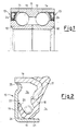
- a rolling contact bearing in particular for the hub of a vehicle wheel, comprises two inner, generally rotating races 10 and an outer, generally stationary race 11, two series of rolling elements 12 are applied between said races, according to a known arrangement for the angular or oblique contact bearings.
- a sealing device is mounted, said sealing device, indicated by numeral 13, closes the annular gap between the inner races and the outer race and does not allow the outside polluting agents (water, dust, mud) to enter into the inner parts of the bearing, and does not allow the lubricating grease, usually contained inside the inner portion 14 of the bearing, to exit from the bearing.
- the sealing device 13 comprises a first annular insert 15, integral with one of the inner races 10, said first annular insert is also known with the term "flinger”, a second annular insert 16, integral with the outer race 11 and a sealing element 17, made of a conductive elastic material as for instance conductive cured rubber, said sealing element is integral with the second annular insert 16 and is in sliding contact with the first annular insert 15.
- the end portion 18 of the element 17 made of conductive rubber has a V shaped axial section and defines two sealing lips 19 and 20 respectively in contact with a cylindric wall 21 and a radial wall 22 of the first insert 15.
- the configuration of the sealing device 13 is such that the component elements define a first annular outer chamber 24, with an opening 25 to the outside and a second hermetically sealed inner chamber 26.
- This second chamber 26 is defined by a portion of the sealing element 17, said portion being comprised between the two contact lips 19 and 20, and by the corresponding portion of the fist insert 15.
- the chamber 26 has an axial substantially triangular shape, since said chamber is defined by two perpendicular walls belonging to the insert 15, and by a substantially straight length 18 of the elastic sealing element, the shape of this second inner chamber may nonetheless change according to the design of the elements defining the sealing device.
- the hermetically sealed chamber 26 contains a conductive grease which improves the electric conductivity of the sealing device in order to discharge therethrough the above discussed electrostatic currents. Since the chamber 26 is hermetically sealed, the conductive grease therein contained can neither be mixed with the lubricating grease contained in the chamber 14 together with the rolling element nor pass into the first chamber 24 which is connected to the external environment.
- the conductive grease contained into the hermetically sealed chamber 26 is preferably made of a polymeric grease containing a minimum percentage (1-2%) of antistatic material (for instance the Dehydat 51, commercialised by Henkel) and/or solid conductive particles, for instance niobium sulphide and carbon with 1-2 ⁇ m dimensions.
- antistatic material for instance the Dehydat 51, commercialised by Henkel
- solid conductive particles for instance niobium sulphide and carbon with 1-2 ⁇ m dimensions.
- the first sealing insert 15 carries its own sealing element 29, preferably made of a conductive elastic material as for instance conductive rubbers or elastomers, said material is slidingly in contact with the second annular insert 16 thus causing also the outer chamber 24' to become hermetically sealed.
- a conductive elastic material as for instance conductive rubbers or elastomers
- at least one of the two elastic sealing elements is a conductive element, and, anyhow, it is preferable that at least the stationary sealing element 17, which is integral with the stationary outer race of bearing, is made of a conductive material.
- the conductive material sealing element shall be the element 29 which is integral with the inner race 10.
- the rotating element 29 is affected by the centrifugal force which pushes said element against the insert 16, whereon said rotating element slides.
- An increase in the contact pressure could in fact cause a quicker wear of the conductive rubber and/or form a permanent deformation which could, with the passing of time, cause the loss of contact between the elastic rotating element and the corresponding insert, thus interrupting the passage of the electric current therethrough.
- the contact pressure of the stationary elastic element 17 is constant and is not affected by the centrifugal force, therefore its sealing characteristics are more reliable.
- FIG 5 another embodiment of the invention is shown, wherein said embodiment refers to a bearing for the hub 30 of a vehicle wheel; the hub 30 forms one of the inner rolling races of the bearing and also forms a flange 31 for the fixing to one of the wheels (not shown) of the autovehicle.
- the outer race 11 is closed, at its end facing the inner side of the vehicle, by a concave cover 32 made of metallic sheet, said cover is inserted inside the diameter at the end of said race; the cover 32 has its concave side facing the head 33 of a bolt 34 suitable to block axially, against the hub 30, a separate race 35, which forms the inner rolling race for the series of the axially inner rolling elements 12.
- the concave or inner surface of the cover 32 is coated with conductive rubber 36 and further forms at least a conical lip 37 which slidingly contacts a conductive rotating element which is integral with the hub in order to realise a conductive bridge between the rotating portion and the stationary portion of the bearing; at the same time the conical lip 37 hermetically separates the inner chamber 14 of the bearing, whereinto there is the lubricating grease, from the conductive hermetically sealed chamber 39, which contains conductive grease and which is defined by the central portion of the cover 32 having the coating 36, from the conical conductive lip 37 and from the rotating parts surface which is surrounded by the conical lip 37.
- the conical lip 37 is, advantageously, in contact with the front radial wall 40 of the inner race 35 which has a low surface roughness and which therefore does not wear the conical lip.
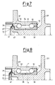
- Figure 7 shows a different embodiment, wherein the elastic sealing element is formed by a couple of conical lips 37, 37' which slide respectively on the front radial wall 40 of the inner race 35 and on the rolled end 41 of the hub 30.
- the conductive grease is contained inside the annular chamber 39 defined by the pips 37, 37' and by those portions of the sliding surfaces 40 and 41 comprised between said lips.
- a conductive rubber element 42 is fixed on the concave surface, facing the hub 30, 32, corresponding with the rolling axis of the bearing, said conductive rubber element forms a sucker projection 43 which slidingly contacts the head 33 of the locking bolt 34.
- the conductive grease containing chamber is the chamber 44 comprised between the bolt head and the sucker projection 43. Since in this case the electric bridge between the inner race and the outer race of the bearing is realised in proximity of the rotations axis, where the tangential component of the relative rotation speed is very low, the wear of the portion made of conductive rubber will be extremely low.
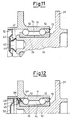
- Figure 11 Another embodiment, similar to the one of Figure 10 is shown in Figure 11, wherein the conductive rubber element 42 forms a sucker projection 43 which slidingly contacts the rolled end 41 of the hub 30.
- the elastic sealing element is formed by a couple of conical lips 37, 37' made of a conductive elastic material cured on an annular metallic insert 45 which is integral with a inner race 35.
- the lips 37, 37' slide against the inner cylindrical surface 46 of the outer rolling race 11, thus defining together with said outer race, an annular chamber 39, containing conductive grease.
Landscapes
- Engineering & Computer Science (AREA)
- General Engineering & Computer Science (AREA)
- Mechanical Engineering (AREA)
- Sealing Of Bearings (AREA)
- Rolling Contact Bearings (AREA)
Applications Claiming Priority (2)
| Application Number | Priority Date | Filing Date | Title |
|---|---|---|---|
| IT97TO000648A IT1293461B1 (it) | 1997-07-17 | 1997-07-17 | Cuscinetto di rotolamento con dispositivo di tenuta e di scarico di correnti elettrostatiche. |
| ITTO970648 | 1997-07-17 |
Publications (3)
| Publication Number | Publication Date |
|---|---|
| EP0892471A2 EP0892471A2 (en) | 1999-01-20 |
| EP0892471A3 EP0892471A3 (en) | 2000-06-28 |
| EP0892471B1 true EP0892471B1 (en) | 2002-09-25 |
Family
ID=11415878
Family Applications (1)
| Application Number | Title | Priority Date | Filing Date |
|---|---|---|---|
| EP98113122A Expired - Lifetime EP0892471B1 (en) | 1997-07-17 | 1998-07-15 | A rolling contact bearing provided with a seal and an electrostatic current discharge device |
Country Status (4)
| Country | Link |
|---|---|
| US (1) | US6109794A (it) |
| EP (1) | EP0892471B1 (it) |
| DE (1) | DE69808191T2 (it) |
| IT (1) | IT1293461B1 (it) |
Cited By (1)
| Publication number | Priority date | Publication date | Assignee | Title |
|---|---|---|---|---|
| DE102009036856A1 (de) | 2009-08-10 | 2011-02-17 | Magna Steyr Fahrzeugtechnik Ag & Co. Kg | Elektrische Maschine mit vor Stromdurchschlägen geschütztem Wälzlager und Getriebemotor mit einem solchen |
Families Citing this family (29)
| Publication number | Priority date | Publication date | Assignee | Title |
|---|---|---|---|---|
| US6608422B2 (en) * | 1999-05-06 | 2003-08-19 | Prestolite Electric, Inc. | Alternator with an electric contact bearing assembly |
| DE10037530A1 (de) * | 1999-08-31 | 2001-03-22 | Ntn Toyo Bearing Co Ltd | Dichtungsvorrichtung für Lager |
| KR100491692B1 (ko) * | 1999-11-15 | 2005-05-25 | 미쓰비시덴키 가부시키가이샤 | 회전베어링 |
| EP1122474B1 (en) * | 2000-01-31 | 2005-10-26 | Teijin Limited | Sealing arrangement between flow regulator and shut-off valve attached to oxygen cylinder |
| US6984906B1 (en) | 2000-07-13 | 2006-01-10 | General Electric Company | Bearing current reduction assembly |
| IT1318196B1 (it) * | 2000-07-19 | 2003-07-28 | Rft Spa | Complesso di tenuta per due organi reciprocamente rotanti, inparticolare i due anelli di un cuscinetto a rotolamento |
| JP2002195277A (ja) * | 2000-10-19 | 2002-07-10 | Nsk Ltd | 転がり軸受 |
| DE10249770B4 (de) * | 2002-10-24 | 2005-11-03 | Sew-Eurodrive Gmbh & Co. Kg | Getriebe |
| DE102005021354A1 (de) * | 2005-05-04 | 2006-11-16 | Vem Sachsenwerk Gmbh | Anordung zum Begrenzen von Überspannungen an Funktionsteilen umrichtergespeister elektrischer Maschinen |
| DE202005016974U1 (de) * | 2005-10-25 | 2006-01-05 | Dettke, Christa | Presseur |
| DE102007048557B3 (de) | 2007-10-09 | 2009-06-04 | Ab Skf | Anordnung zum Abdichten |
| DE102008000854B4 (de) | 2008-03-27 | 2011-12-22 | Zf Friedrichshafen Ag | Kugelgelenk, Spurstange und Lenkvorrichtung |
| US8264347B2 (en) * | 2008-06-24 | 2012-09-11 | Trelleborg Sealing Solutions Us, Inc. | Seal system in situ lifetime measurement |
| CN102356706A (zh) * | 2009-03-06 | 2012-02-15 | 美国圣戈班性能塑料公司 | 重叠的螺旋导电弹簧 |
| SG179014A1 (en) * | 2009-10-02 | 2012-04-27 | Saint Gobain Performance Plast | Modular polymeric emi/rfi seal |
| DE102010022320A1 (de) * | 2010-06-01 | 2011-12-01 | Schaeffler Technologies Gmbh & Co. Kg | Elektrischer Radantrieb |
| DE102010055178A1 (de) | 2010-12-20 | 2012-06-21 | Axel R. Hidde | Gedichtete Lageranordnung mit semipermeabler Elastomer-Membran |
| DE202010017137U1 (de) | 2010-12-20 | 2012-01-02 | Axel R. Hidde | Gedichtete Lageranordnung mit semipermeabler Elastomer-Membran |
| US9088197B2 (en) * | 2011-09-07 | 2015-07-21 | General Electric Company | Shaft grounding system |
| DE102012204795A1 (de) * | 2012-03-26 | 2013-09-26 | Schaeffler Technologies AG & Co. KG | Radnabenmotor mit Potenzialausgleich |
| US8992091B2 (en) * | 2012-05-11 | 2015-03-31 | Schaeffler Technologies AG & Co. KG | Closure design of a conductive rubber material for allowing current passage through a bearing in electric machines |
| JP6081179B2 (ja) * | 2012-12-14 | 2017-02-15 | Nok株式会社 | 密封装置 |
| DE102013000982B4 (de) * | 2013-01-22 | 2015-10-29 | Carl Freudenberg Kg | Dichtring und Dichtungsanordnung damit |
| DE102014010269B4 (de) * | 2014-07-11 | 2020-06-18 | Carl Freudenberg Kg | Vorschaltdichtung, Vorschaltdichtungsanordnung und Dichtring, umfassend die Vorschaltdichtung |
| JP6281501B2 (ja) * | 2015-01-29 | 2018-02-21 | トヨタ自動車株式会社 | 車両の車輪支持装置 |
| DE102016209581A1 (de) * | 2016-06-01 | 2017-12-07 | Volkswagen Aktiengesellschaft | Kontaktanordnung für eine elektrische Maschine |
| US20180195407A1 (en) * | 2017-01-12 | 2018-07-12 | Pratt & Whitney Canada Corp. | Aircraft engine having seal assembly defining an electrically conductive path |
| FR3077949A1 (fr) * | 2018-02-15 | 2019-08-16 | Renault S.A.S | Dispositif de mise a la masse d'un arbre tournant dans un carter et reducteur de vitesse |
| US11035413B1 (en) | 2020-01-10 | 2021-06-15 | Aktiebolaget Skf | Bearing with conductive medium |
Family Cites Families (17)
| Publication number | Priority date | Publication date | Assignee | Title |
|---|---|---|---|---|
| US3564477A (en) * | 1969-08-11 | 1971-02-16 | Gen Motors Corp | Conductor seal |
| DE2861278D1 (en) * | 1978-06-05 | 1982-01-14 | Stefa Industri Ab | Sealing device for bearings, especially roll bearings |
| DE3147495A1 (de) * | 1981-12-01 | 1983-06-09 | Mueller Georg Nuernberg | Waelzlager-abdichtung |
| JPS6343067A (ja) * | 1986-08-07 | 1988-02-24 | Nok Corp | 発熱性シ−ル材 |
| US4856916A (en) * | 1987-09-19 | 1989-08-15 | Ntn Toyo Bearing Co., Ltd. | Conducting rolling bearing |
| FR2666937B1 (fr) * | 1990-09-13 | 1994-07-01 | Skf France | Palier a roulement a contacts electriques tournants. |
| FR2678691B1 (fr) * | 1991-07-05 | 1995-04-21 | Skf France | Dispositif de capteur de vitesse de rotation pour roulements et roulement equipe d'un tel dispositif. |
| IT1250840B (it) * | 1991-09-26 | 1995-04-21 | Skf Ind Spa | Sensore passivo con avvolgimento a basso numero di spire. |
| FR2700588B1 (fr) * | 1993-01-19 | 1995-02-17 | Roulements Soc Nouvelle | Dispositif de montage à joint d'étanchéité à codeur incorporé. |
| JPH07127647A (ja) * | 1993-11-04 | 1995-05-16 | Nippon Seiko Kk | 回転支持装置 |
| US5470157A (en) * | 1994-03-29 | 1995-11-28 | The Timken Company | Bearing seal for sensing angular velocity |
| IT1273173B (it) * | 1994-05-03 | 1997-07-07 | Skf Ind Spa | Gruppo sensore e di tenuta per un cuscinetto di rotolamento |
| JP3231185B2 (ja) * | 1994-07-15 | 2001-11-19 | 日本精工株式会社 | 回転速度検出装置付転がり軸受ユニット |
| US5454724A (en) * | 1994-07-22 | 1995-10-03 | Seagate Technology, Inc. | Floating electrical contact for spindle motor |
| FR2730566B1 (fr) * | 1995-02-09 | 1997-06-13 | Skf France | Dispositif de codeur pour capteur de vitesse de rotation et roulement equipe d'un tel dispositif |
| SE9600408L (sv) * | 1996-02-05 | 1997-08-06 | Skf Ab | Rullningslager |
| IT1292297B1 (it) * | 1997-04-29 | 1999-01-29 | Skf Ind Spa | Complesso di tenuta sensorizzato per due organi in rotazione relativa, in particolare per un cuscinetto di rotolamento. |
-
1997
- 1997-07-17 IT IT97TO000648A patent/IT1293461B1/it active IP Right Grant
-
1998
- 1998-07-15 EP EP98113122A patent/EP0892471B1/en not_active Expired - Lifetime
- 1998-07-15 DE DE69808191T patent/DE69808191T2/de not_active Expired - Lifetime
- 1998-07-16 US US09/116,532 patent/US6109794A/en not_active Expired - Lifetime
Cited By (2)
| Publication number | Priority date | Publication date | Assignee | Title |
|---|---|---|---|---|
| DE102009036856A1 (de) | 2009-08-10 | 2011-02-17 | Magna Steyr Fahrzeugtechnik Ag & Co. Kg | Elektrische Maschine mit vor Stromdurchschlägen geschütztem Wälzlager und Getriebemotor mit einem solchen |
| WO2011018447A1 (de) | 2009-08-10 | 2011-02-17 | Magna Steyr Fahrzeugtechnik Ag & Co Kg | Elektrische maschine mit vor stromdurchschlägen geschütztem wälzlager und getriebemotor mit einem solchen |
Also Published As
| Publication number | Publication date |
|---|---|
| EP0892471A2 (en) | 1999-01-20 |
| EP0892471A3 (en) | 2000-06-28 |
| DE69808191T2 (de) | 2003-02-13 |
| DE69808191D1 (de) | 2002-10-31 |
| US6109794A (en) | 2000-08-29 |
| ITTO970648A1 (it) | 1999-01-17 |
| IT1293461B1 (it) | 1999-03-01 |
Similar Documents
| Publication | Publication Date | Title |
|---|---|---|
| EP0892471B1 (en) | A rolling contact bearing provided with a seal and an electrostatic current discharge device | |
| EP0864770B1 (en) | Seal device for rolling bearing | |
| EP0905394B1 (en) | Package bearing with retainer | |
| US4783180A (en) | Bearing assembly for vehicle | |
| EP1041387B1 (en) | Combination seal ring with encoder | |
| US5096207A (en) | Cartridge seal with dual lipped secondary seal | |
| EP0902203B1 (en) | Sealing assembly for a rolling bearing | |
| CN100374730C (zh) | 水泵用密封装置和水泵用旋转支撑装置及水泵 | |
| EP0304160B1 (en) | Seal assembly | |
| EP1469239B1 (en) | A bearing for a wheel of vehicle | |
| CN113939663B (zh) | 密封装置 | |
| JP2000509791A (ja) | 軸受構造のための封止装置及び軸受装置の封止のための構造 | |
| JP2525536Y2 (ja) | 密封装置 | |
| EP1436152B1 (en) | Rotation-support apparatus with rotation sensor device for drive-wheel | |
| US6231239B1 (en) | Bearing bush with center flange | |
| US11965558B2 (en) | Sealing device | |
| US6357751B1 (en) | Protective element for a sealing arrangement with at least one sealing ring, sealing arrangement with such a protective element as well as method for keeping away dirt particles from such a sealing arrangement | |
| EP1956258B1 (en) | Sealing apparatus and bearing apparatus having the same | |
| JP7119919B2 (ja) | ハブユニット軸受 | |
| US20240263674A1 (en) | Boot assembly of drive axle | |
| JP2003035565A (ja) | 磁気エンコーダおよびこれを具備する車輪用軸受 | |
| JP4654779B2 (ja) | シール部材及びシール部材付き転がり軸受ユニット | |
| US6786644B2 (en) | Sealing device for rolling bearings | |
| JP2002048147A (ja) | 車軸用軸受の密封装置 | |
| EP2551542B1 (en) | Wheel-hub bearing/constant-velocity joint unit provided with a protective screen |
Legal Events
| Date | Code | Title | Description |
|---|---|---|---|
| PUAI | Public reference made under article 153(3) epc to a published international application that has entered the european phase |
Free format text: ORIGINAL CODE: 0009012 |
|
| AK | Designated contracting states |
Kind code of ref document: A2 Designated state(s): DE FR |
|
| AX | Request for extension of the european patent |
Free format text: AL;LT;LV;MK;RO;SI |
|
| PUAL | Search report despatched |
Free format text: ORIGINAL CODE: 0009013 |
|
| AK | Designated contracting states |
Kind code of ref document: A3 Designated state(s): AT BE CH CY DE DK ES FI FR GB GR IE IT LI LU MC NL PT SE |
|
| AX | Request for extension of the european patent |
Free format text: AL;LT;LV;MK;RO;SI |
|
| 17P | Request for examination filed |
Effective date: 20000908 |
|
| AKX | Designation fees paid |
Free format text: DE FR |
|
| 17Q | First examination report despatched |
Effective date: 20010212 |
|
| GRAG | Despatch of communication of intention to grant |
Free format text: ORIGINAL CODE: EPIDOS AGRA |
|
| GRAG | Despatch of communication of intention to grant |
Free format text: ORIGINAL CODE: EPIDOS AGRA |
|
| GRAH | Despatch of communication of intention to grant a patent |
Free format text: ORIGINAL CODE: EPIDOS IGRA |
|
| GRAH | Despatch of communication of intention to grant a patent |
Free format text: ORIGINAL CODE: EPIDOS IGRA |
|
| GRAA | (expected) grant |
Free format text: ORIGINAL CODE: 0009210 |
|
| AK | Designated contracting states |
Kind code of ref document: B1 Designated state(s): DE FR |
|
| REF | Corresponds to: |
Ref document number: 69808191 Country of ref document: DE Date of ref document: 20021031 |
|
| ET | Fr: translation filed | ||
| PLBE | No opposition filed within time limit |
Free format text: ORIGINAL CODE: 0009261 |
|
| STAA | Information on the status of an ep patent application or granted ep patent |
Free format text: STATUS: NO OPPOSITION FILED WITHIN TIME LIMIT |
|
| 26N | No opposition filed |
Effective date: 20030626 |
|
| PGFP | Annual fee paid to national office [announced via postgrant information from national office to epo] |
Ref country code: FR Payment date: 20050718 Year of fee payment: 8 |
|
| REG | Reference to a national code |
Ref country code: FR Ref legal event code: ST Effective date: 20070330 |
|
| PG25 | Lapsed in a contracting state [announced via postgrant information from national office to epo] |
Ref country code: FR Free format text: LAPSE BECAUSE OF NON-PAYMENT OF DUE FEES Effective date: 20060731 |
|
| PGFP | Annual fee paid to national office [announced via postgrant information from national office to epo] |
Ref country code: DE Payment date: 20121001 Year of fee payment: 15 |
|
| PG25 | Lapsed in a contracting state [announced via postgrant information from national office to epo] |
Ref country code: DE Free format text: LAPSE BECAUSE OF NON-PAYMENT OF DUE FEES Effective date: 20140201 |
|
| REG | Reference to a national code |
Ref country code: DE Ref legal event code: R119 Ref document number: 69808191 Country of ref document: DE Effective date: 20140201 |