EP0892612B1 - Kartoffelschälvorrichtung - Google Patents
Kartoffelschälvorrichtung Download PDFInfo
- Publication number
- EP0892612B1 EP0892612B1 EP97906758A EP97906758A EP0892612B1 EP 0892612 B1 EP0892612 B1 EP 0892612B1 EP 97906758 A EP97906758 A EP 97906758A EP 97906758 A EP97906758 A EP 97906758A EP 0892612 B1 EP0892612 B1 EP 0892612B1
- Authority
- EP
- European Patent Office
- Prior art keywords
- plate
- drum
- abrasive
- potatoes
- liner
- Prior art date
- Legal status (The legal status is an assumption and is not a legal conclusion. Google has not performed a legal analysis and makes no representation as to the accuracy of the status listed.)
- Expired - Lifetime
Links
- 235000002595 Solanum tuberosum Nutrition 0.000 title description 169
- 244000061456 Solanum tuberosum Species 0.000 title description 169
- 235000013305 food Nutrition 0.000 claims description 7
- 238000007599 discharging Methods 0.000 claims description 2
- 238000000034 method Methods 0.000 claims description 2
- 235000012015 potatoes Nutrition 0.000 description 133
- 206010040844 Skin exfoliation Diseases 0.000 description 78
- XLYOFNOQVPJJNP-UHFFFAOYSA-N water Substances O XLYOFNOQVPJJNP-UHFFFAOYSA-N 0.000 description 10
- 230000004580 weight loss Effects 0.000 description 10
- 230000006378 damage Effects 0.000 description 9
- 239000003082 abrasive agent Substances 0.000 description 8
- 208000027418 Wounds and injury Diseases 0.000 description 7
- 208000014674 injury Diseases 0.000 description 7
- 239000000463 material Substances 0.000 description 7
- 230000007423 decrease Effects 0.000 description 6
- 238000003860 storage Methods 0.000 description 6
- 239000007788 liquid Substances 0.000 description 5
- 239000002184 metal Substances 0.000 description 3
- 230000000007 visual effect Effects 0.000 description 3
- 238000004590 computer program Methods 0.000 description 2
- 229920001778 nylon Polymers 0.000 description 2
- 239000007921 spray Substances 0.000 description 2
- 229920002994 synthetic fiber Polymers 0.000 description 2
- 239000012209 synthetic fiber Substances 0.000 description 2
- 230000032258 transport Effects 0.000 description 2
- 238000010924 continuous production Methods 0.000 description 1
- 239000000835 fiber Substances 0.000 description 1
- 235000012055 fruits and vegetables Nutrition 0.000 description 1
- 238000004519 manufacturing process Methods 0.000 description 1
- 238000012544 monitoring process Methods 0.000 description 1
- 238000003825 pressing Methods 0.000 description 1
- 238000011144 upstream manufacturing Methods 0.000 description 1
Images





Classifications
-
- A—HUMAN NECESSITIES
- A23—FOODS OR FOODSTUFFS; TREATMENT THEREOF, NOT COVERED BY OTHER CLASSES
- A23N—MACHINES OR APPARATUS FOR TREATING HARVESTED FRUIT, VEGETABLES OR FLOWER BULBS IN BULK, NOT OTHERWISE PROVIDED FOR; PEELING VEGETABLES OR FRUIT IN BULK; APPARATUS FOR PREPARING ANIMAL FEEDING- STUFFS
- A23N7/00—Peeling vegetables or fruit
- A23N7/02—Peeling potatoes, apples or similarly shaped vegetables or fruit
Definitions
- the invention relates to a drum-type batch peeler for peeling potatoes and other food products of the kind disclosed in FR-A-2 558 690.
- Drum-type batch potato peelers typically include a cylindrical drum with an abrasive material mounted on the inner surface of the drum.
- a rotary floor or plate is provided at the bottom of the drum.
- a batch of potatoes is placed in the drum, rotated by the floor and thrown up by centrifugal force against the abrasive material. Frictional contact between the potatoes and the material peels the potatoes. After the batch has been peeled for a period of time, the peeled potatoes are discharged for subsequent processing.
- the liner has a single grade of abrasive, typically a coarse sand-like abrasive, a medium sand-like abrasive or a soft fiber brush.
- abrasive typically a coarse sand-like abrasive, a medium sand-like abrasive or a soft fiber brush.
- Different grades of abrasive are required in order to peel potatoes having different types of skin. For instance, spring potatoes have delicate skins and are best peeled using a medium abrasive or brush liner. Potatoes with thick and tough skins are best peeled using a coarse abrasive liner.
- the liners in conventional batch peelers are secured to the drums during peeling.
- the rotary floor or plate of conventional drum-type batch peelers rotates at a fixed speed during filling of the peeler, peeling and discharge of peeled potatoes from the peeler.
- the fixed speed is relatively high in order to efficiently peel potatoes.
- the high speed rotation of the plate is likely to injure the potatoes when batches are fed into the peeler and when peeled potatoes are discharged from the peeler.
- Conventional potato peeling systems are not adjustable during operation other than by varying the length of time the potatoes are in the peeler.
- the inflexibility means that a machine set up to peel a potato with a particular type of skin and surface configuration cannot be easily converted to peel potatoes with different types of skin.
- the invention may be applied to a potato peeling apparatus using an adjustable drum-type batch peeler.
- the peeler includes a number of interior bands of different grade abrasive and a drive for raising and lowering the bands in the peeler to position a selected abrasive band immediately above the rotary plate during peeling.
- the band is selected to meet the peel requirements of the particular potatoes being peeled.
- the disclosed peeler according to a first embodiment includes an adjustable liner with three abrasive bands, a rough abrasive grit band, a medium or fine abrasive grit band, and a brush band on a single liner. The liner is moved vertically in the drum to position a selected band immediately above the plate for peeling.
- the disclosed peeler according to a second embodiment includes a plurality of independently movable cylindrical liners with a band of different grade abrasive on the inner surface of each liner. These liners nest inside each other and are moved vertically in the drum to position a liner with a selected band of abrasive immediately above and facing the plate. The other liners may be outside or vertically spaced from the liner with the selected abrasive band. Potatoes may be peeled by positioning two bands above the plate so that the potatoes are thrown up against two bands of different abrasive.
- the rotary bottom plate of the peeler is driven by an adjustable speed drive so that the rotary speed of the plate may be slowed during feeding of a batch of potatoes into the peeler and during discharge of a batch of peeled potatoes from the peeler. Slowing the bottom plate reduces injury to the potatoes.
- Each batch of unpeeled potatoes fed into the peeler is automatically weighed and is again weighed after peeling in order to determine the percentage of weight loss during peeling.
- the percentage of weight lost for successive batches is averaged by a computer control system and is then compared to a desired percentage weight loss.
- Peel parameters including the ⁇ peel time, the abrasive band or bands used during peeling and the speed of the rotary bottom plate are automatically adjusted in order to attain the desired percentage weight loss for successive batches of peeled potatoes.
- the peeling apparatus also includes a television monitoring assembly which automatically determines the amount of unpeeled skin left on peeled potatoes to assure that the potatoes meet minimum visual requirements. If peeling to a desired weight loss leaves too much or too little skin on the potatoes, then the peeling parameters are further adjusted to assure the peeled potatoes meet visual requirements.
- the control system of the potato peeling apparatus permits automatic adjustment of the peeling operation to preset standards, despite variation in the quality of potatoes in each peel batch. This feature assures efficient production-line operation with minimum manual intervention and reduced cost. Further, information concerning the peel properties of particular types of potatoes can be developed and stored for retrieval and future use.
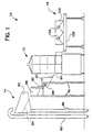
- potato peeling system 10 includes a drum-type batch peeler apparatus 12, an unpeeled potato infeed assembly 14 located upstream from the peeler and a peeled potato discharge assembly 16 located downstream from the peeler.
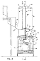
- Batch peeler 12 includes a rectangular base 18 with a cylindrical drum 20 mounted on the top of the base and a vertically oriented cylindrical liner 22 fitted within the drum 20. The bottom of the drum is open. The liner 22 has a close sliding fit within the drum and when lowered extends partially into base 18. Liner drive 24 moves the liner vertically between a fully raised position shown in Figure 6 and a fully lowered position shown in Figure 3.
- Potato driving rotary plate 26 is located at the bottom of the outer drum and is spaced a short distance inwardly from the drum to provide a circumferential gap between the plate and drum sufficiently wide to permit vertical movement of the liner.
- the plate includes an upwardly formed elliptical portion which, when rotated, drives or throws potatoes in the peeler against an abrasive band on the interior of the liner to peel the potatoes.
- Plate drive 40 is located in base 18 and includes drive motor 28, gear box 30 and drive train 32 connected to a drive shaft 34 supporting the plate.
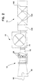
- Shaft 34 is mounted on the base through a suitable bearing so that operation of motor 28 rotates plate 26 in the direction of arrows 36 as shown in Figure 7.
- Bearing socket 38 is mounted on the top of plate 26 above shaft 34.
- the plate drive 40 is located in a sheet metal shroud 42 with shaft 34 extending outwardly through a central opening in the shroud.
- the shroud protects the drive from liquid and peelings falling down from drum 20.
- the liquid and peelings are collected in a drain pan 44 mounted on the bottom of base 18 and are removed.
- Liner 22 includes an outer cylindrical metal tube or body 46 having a sliding fit in drum 20.
- Three vertically spaced bands of abrasive peeling material are secured on the interior cylindrical surface of tube 46 with a brush band 48 located at the bottom of the tube, a medium abrasive band 50 located at the middle of the tube and a coarse band 52 located at the top of the tube.
- the lower brush band is formed of short inwardly facing synthetic fibers, which may be nylon fibers, having a length of about 1/8 to 3/16 inches (0.32 to 0.48 cm).
- the center medium abrasive band comprises a medium abrasive grit adhered to the tube 46.
- the upper coarse abrasive band 52 comprises a relatively coarse abrasive grit.
- the brushes and grits attached to liner 22 are each used in conventional single band batch peelers and need not be described further.
- the bands may be formed of other peeling materials, if desired.
- the center abrasive band may be a fine abrasive grit.
- Inwardly facing elliptical projections 52 are spaced around the abrasive bands to tumble potatoes and improve peeling.
- a number of anti-rotation vertical ribs 54 are secured to the outer surface of tube 46 and slide up and down in vertical slots 56 formed in drum 20.
- the ribs prevent potatoes thrown up against an abrasive band during peeling from rotating the tube in the drum. Only one rib is shown. If desired, other types of anti-rotation connections between the tube and drum may be used.
- the liner drive 24 includes a drive motor 58 mounted on the top of drum 20 above bearing socket 38 by a number of radial support arms 60 extending from the top of the drum to the motor.
- the output shaft of motor 58 is connected to an elongate threaded positioning shaft 62 having a lower end seated in socket 38 to permit relative rotation between the shaft and plate 26.
- Drive nut 64 is threadable mounted on shaft 62 and is connected to the top of liner 22 by a number of radial arms 66.
- Vertically extendable and contractible drive 24 is connected between the liner tube or body 46 and plate 26.
- the drive is connected to the body through arms 66 and is connected to the plate through arms 60, drum 20, base 18, and plate drive 40. Actuation of the drive moves the liner vertically relative to the vertically fixed plate. It is contemplated that a drive could move the plate vertically relative to a fixed liner in order to position the plate adjacent to a desired abrasive band for peeling.
- a collapsible shaft shroud 68 surrounds the portion of shaft 62 extending between plate 26 and drive nut 64 and includes a number of nested tubular segments 70 (see Fig. 6).
- the shroud protects the shaft 62 from liquid and peelings generated during operation of the peeler 12 and prevents potatoes from contacting the shaft.
- the shroud has a maximum height extending from the plate to the top of the drum 20 as shown in Figure 6, and a minimum collapsible height equal to approximately the height of one band, as shown in Figure 3.
- a potato inlet opening 72 is provided in drum 20 a distance above plate 26 equal to the vertical height of the upper band 52. See Figure 3.
- Potato inlet chute 74 surrounds opening 72 and extends upwardly from the opening. As shown in Figures 2 and 7, chute 74 extends away from one side of the drum so that potatoes discharged through the chute and into the liner are grouped to one side of the central threaded shaft. The chute discharges the potatoes into the peeler in generally the same direction the plate 26 moves below the opening 72, to reduce injury to the potatoes during charging of the peeler.
- Potato discharge opening 76 is provided in drum 20 above plate 26 and directly across the drum from opening 72, on the same side of the shaft 62 as opening 72.
- Potato discharge chute 78 surrounds discharge opening 76 and extends outwardly from one side of the drum to receive potatoes thrown outwardly by rotation of plate 26 when the liner 22 is fully raised as shown in Figure 6. The peeled potatoes are thrown radially outwardly by rotation of plate 26 and are guided into the chute with minimum injury.
- Infeed assembly 14 includes a vertical infeed pipe 80 with a rotary auger (not illustrated) in the pipe operable to lift unpeeled potatoes and water to elevated flume 82.
- the flume is provided with a grate 84 which permits the water to drain away through return pipe 86.
- Unpeeled potatoes are discharged from the flume into elevated storage hopper 88 having an outlet door 90 located above weigh hopper 92.
- the weigh hopper includes a discharge door 94 at the lower end of the hopper located in inlet chute 74 of peeler 12. Doors 90 and 94 are selectively opened and closed by door drives (not illustrated).
- Both hoppers 88 and 92 are supported on frame 96.
- Weigh hopper 92 is secured to the frame by a number of load cells 98.
- Load cells 98 are connected to a control circuit (not illustrated) which determines the weight of a batch of unpeeled potatoes held in the weigh hopper for discharge into the peeler.
- the discharge assembly 16 includes a weigh belt conveyor 100 extending downstream from discharge chute 78.
- Television camera housing 102 is positioned above weigh belt conveyor 100 and supports a pair of television viewing cameras 104.
- the cameras are spaced along the length of the conveyor and have widths of field extending across the width of the conveyor belt.
- cameras 110 take instantaneous pictures of the potatoes against a white background. Remaining skin on the potatoes is shown in the pictures as dark areas.
- the cameras are connected to circuitry which counts the number of pixels in each dark area and then sums the number of dark-area pixels to generate an output proportional to the area of unpeeled skin for each batch of peeled potatoes discharged from peeler 12.
- Operation of the potato peeling system 10 is automatically controlled by a computer system responsive to a number of inputs to maximize peeling efficiency in accordance with peel standards for particular types of potatoes.
- the computer system includes a programmable logic controller (PLC) responsive to inputs including the weight of a batch of unpeeled potatoes delivered to the peeler from weigh hopper 92 as determined by load cells 98, the weight of the peeled batch of potatoes as determined by the weigh belt conveyor 100 and the area of unpeeled skin left on the peeled potatoes in the batch as determined by counting the dark pixels viewed by cameras 104.
- PLC programmable logic controller
- the operation of the batch peeler may be controlled by the PLC or manually to vary the rotary speed of bottom plate 26, the duration of the peel for each batch, and the time during the peel the potatoes are peeled against a particular abrasive band.
- the rotational speed of the plate 26 is slowed to approximate the velocity of the potatoes as they are discharged into the peeler in order to reduce impact injury to the potatoes.
- the rotational speed of plate 26 is also slowed during discharge to reduce impact injury.
- Unpeeled potatoes are delivered to storage hopper 88 and are discharged from the hopper in batches into the weigh hopper 92 by opening door 90.
- the load cells 98 determine the weight of each batch of unpeeled potatoes prior to discharge into peeler 12.
- the liner drive motor 58 Prior to discharge of a batch of potatoes into the peeler, the liner drive motor 58 is actuated to fully lower liner 22 to the position of Figure 3 where the top of the liner is located below inlet opening 72. When in this position, the liner does not obstruct discharge of a batch of potatoes from hopper 92 into the peeler. Also, the speed of drive motor 28 is reduced to reduce the rotational speed of plate 26 to approximate the speed of the potatoes as they fall down through chute 74 and opening 72 and onto the plate. In this way, impact injury to the unpeeled potatoes due to the fall is reduced. For instance, for a liner having an interior diameter of about three feet (92.2 cm) where the bottom of the inlet opening 72 is approximately 16 inches (41 cm) above plate 26, the rotational speed of the plate may be slowed to about 52 rpm.
- discharge door 94 is opened to allow the batch of weighed unpeeled potatoes in the storage hopper to fall into the peeler.
- motor 58 is actuated to raise the liner 22 to position either band 50 or 48 above plate 26, if the potatoes are to be peeled by the medium or fine abrasive grit or by the brush bands.
- the motor is not actuated if the potatoes are to be peeled by coarse band 52.
- motor 28 is accelerated to rotate plate 26 at a peeling speed of from 103 to 125 revolutions per minute for a three foot(92.2 cm) diameter peeler.
- High speed rotation of the plate rotates and throws the potatoes outwardly against the band extending upwardly from the plate.
- the potatoes are not thrown higher than the top of the band.
- the potatoes are peeled as they move along the abrasive surface and across the inward projections 53.
- the projections 53 tumble the potatoes on the abrasive to improve peeling. Peeling is continued until a desired quality peel has been achieved. For instance, it may be necessary to peel the potatoes until all or nearly all of the potato peel has been removed. Alternatively, a lighter peel, with a greater amount of skin left on the potato, may be required. This type of peel could be advantageous where it is desirable to remove a minimum percentage by weight of potato during peeling, thereby maximizing the weight of the final food product made from the peeled potato.
- the peel may be advantageous to initiate the peel using one of the grit bands of abrasive 50 and 52 and then finishing the peel using the less abrasive and gentler brush band 48.
- This is easily accomplished by actuating motor 58 during peeling to raise the liner in the drum sufficiently so that the brush band is positioned above rotating plate 26.
- This operation may be performed during peeling without the necessity of slowing plate 26.
- the drive 24 may be used to raise or lower the liner during peeling to facilitate peeling a given batch of potatoes using any or a number of the three bands, as required for a particular peel.
- the peeler includes a conventional spray system (not illustrated) which delivers water into the liner during peeling to aid in peeling and discharge of peeled skin from the liner. The water and peelings fall down on to pan 44.
- drive 24 is actuated to fully raise the liner 22 in drum 20 and uncover the discharge opening 76.
- drive 24 is actuated to fully raise the liner 22 in drum 20 and uncover the discharge opening 76.
- plate 26 preferably slowed to prevent damage to the potatoes, discharges the batch of peeled potatoes through chute 78 and onto weigh belt conveyor 100.
- the conveyor moves the peeled potatoes downstream away from the peeler and spreads the potatoes across the conveyor. As the potatoes move along the conveyor, sensors in the conveyor determine the weight the peeled potatoes.
- the control system compares the weight of the peeled batches with the weight of unpeeled batches when in the weigh hopper to determine the average percentage of weight lost for a number of batches.
- the system compares the determined average weight lost with the desired loss and then automatically adjusts the length of the peel, or in some cases, the abrasive band or bands used during peeling, in order to increase or decrease weight loss so that the actual weight loss matches the desired weight loss. This adjustment is performed automatically by the control system in accordance with the computer program for the particular peeler.
- cameras 140 take pictures of the potatoes and determine the percentage of skin remaining on the potatoes.
- the potatoes tumble as they move along the conveyor.
- the cameras take pictures of the potatoes in different positions to provide an accurate assessment of the percentage of skin remaining on the potatoes. If the percentage of skin remaining on the potatoes is greater than a visual standard, the control system automatically adjusts the peel parameters to remove more skin until the standard is met.
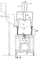
- a second embodiment of potato peeling system is illustrated in Figures 10-16 of the drawings.
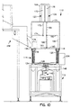
- the second peeling system includes potato peeling apparatus 110 having a rectangular base 112, a cylindrical drum 114 mounted on the top of the base 112, and three vertically movable, cylindrical liners 116, 118 and 120 in the drum.
- the liners are located inside the drum 114 and are individually movable up and down in the drum.
- Liners 116, 118 and 120 are arranged nested inside each other with outermost liner 116 adjacent the drum, liner 118 between liner 116 and liner 120, and liner 120 inside liner 118.
- the diameter of liner 116 is greater than the diameter of liner 118 and the diameter of liner 118 is greater than the diameter of liner 120.
- the bottom of the drum is open.
- Peeler 110 includes a liner drive with like liner subdrives 122, 124 and 126 mounted on cover 171 of drum 114 and joined to liners 116, 118 and 120, respectively.
- the liner drives 122, 124 and 126 move the liners vertically between lowered positions in the drum as shown in Figure 10 and raised positions as shown in Figure 14.
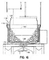
- the liner drives also permit a liner to be positioned in a partially raised position as shown in Figure 16 where the abrasive on the liner 120 is located in the upper portion of the drum and the abrasive on liner 118 is exposed at the bottom of the drum.
- Potato driving rotary plate 128 is located at the bottom of the drum 114 and is spaced a short distance inwardly from the drum to provide a gap between an outer edge of plate 128 and the inner surface of the drum.
- the top of plate 128 includes a pair of diametrically opposed high regions 130 and a pair of diametrically opposed low regions 132 (see Fig. 11).
- the vertical variations in the surface of the plate between adjacent regions aid in tumbling the potatoes to increase the efficiency of the peeling operation.
- Plate 128 forms a raised lip 134.
- Plate 128 includes drainage slots 136 and 138 for drainage of the water from the peeler 110.
- Each low region 132 includes two elongate slots 136 located radially inward of and below the lip 134 and a short slot 138 located between slots 136 at approximately the low point of the low region 132.
- the slots 138 are located a short distance inwardly from slots 136. The slots permit drainage of water through the plate but do not injure or capture potatoes during peeling.
- Plate drive 140 is located in base 112 beneath plate 128 and includes plate drive motor 142, gear box 144 and drive train 146 connected to a drive shaft 148 supporting the plate.
- Shaft 148 is mounted on the base 112 through a suitable bearing so that operation of motor 142 rotates plate 128 in the direction of arrows 150 as shown in Figure 11.
- Plate drive 140 is located in metal shroud 154 with shaft 148 extending outwardly through a central opening in the shroud.
- the shroud protects the drive from liquid and peelings falling down from drum 114.
- the liquid and peelings are collected in a drain pan 156 mounted on the bottom of base 112 and are removed.
- liners 116, 118 and 120 each include an outer cylindrical tube or body 158, 160 and 162, respectively.
- a band of abrasive peeling material is secured on the interior cylindrical surface of each body 158, 160 and 162.
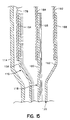
- the upper portion 164 of body 158 is flared radially outwardly from the circumference of body 158 providing a gap between the upper portion 164 and an upper portion 166 of body 160.
- the upper portion 168 of body 162 is flared radially inwardly from the circumference of body 162 providing a gap between the upper portion 166 and the upper portion 168.
- the gaps facilitate attachment of the liners to the liner drives.
- the abrasive peeling material secured to outer liner body 158 is formed of short inwardly facing synthetic fibers, which may be nylon fibers, having a length of about 1/8 to 3/16 inches (0.32 to 0.48 cm).
- the abrasive material secured to middle liner body 160 comprises a medium abrasive grit.
- the abrasive material secured to inner liner body 162 comprises a relatively course abrasive grit.
- Other peeling materials may be substituted for the above mentioned materials, if desired.
- the middle liner body 160 may comprise a fine abrasive grit.
- Liner drive 122 for outer liner 116 includes a drive cylinder 170 mounted on drum cover 171, a vertical shaft 172 operably joined to drive cylinder 170 extending downward into drum 114, three radial ribs 174 join to the lower end of shaft 172 and extending outwardly, and three circumferentially spaced vertical arms 176 extending downwardly from the outer ends of ribs 174 to the top 164 of liner 116.
- Liner drive 124 for middle liner 118 includes a drive cylinder 178 mounted on drum cover 171, a vertical shaft 180 operably joined to drive cylinder 178 extending down towards drum 114, three radial ribs 182 joined to the lower end of shaft 180 extending outwardly, and three circumferentially spaced vertical arms 184 extending downwardly from the outer ends of ribs 182 to the top 166 of liner 118.
- Liner drive 126 for inner liner 120 includes a drive cylinder 186 mounted on drum cover 171, a long vertical shaft 188 operably joined to drive cylinder 186 extending down towards drum 114, three radial ribs 190 joined to the lower end of shaft 188 extending outwardly, and three circumferentially spaced short vertical arms 192 extending downwardly from the outer ends of ribs 190 to the top 168 of liner 120.
- Shaft 188 is approximately twice as long as shafts 172 and 180, and arms 192 are very short. If desired, the ends of ribs 190 may be directly joined to the top of inner liner 120.
- Drive cylinders 170, 178 and 186 are mounted on top of drum 114 within drive housing 194 on cover 171.
- Vertical arms 176, 184 and 192 are spaced around the top edges of their respective liners. Each set of arms occupies an approximate 120° arc around the drum 114. The three arms of each set of vertical arms 176, 184 and 192 are preferably equally spaced from each other along the 120° arc. The spacing allows each liner drive to operate independently of the other drives and raise and lower the liners independently of the positions of the other liners.
- Liner drives 122, 124 and 126 are secured against rotation and prevent rotation of the liners during peeling because of impacts with rotating potatoes.
- ribs 174 extend over the tops of the inner liner 120 and intermediate liner 118.
- ribs 182 extend over the top of the inner liner 160.
- the vertical arms 176 and 184 extend downwardly from ribs 174 and 182 a distance equal or somewhat greater than the working height to which potatoes are thrown up during peeling. Compare Figures 12 and 16. This arrangement allows the inner liner 120 to be raised with liners 116 and 118 fully lowered. See Figure 12.
- the drum has height above the plate 128 approximately three times the working height to accommodate the liners and the drive ribs and arms.
- the drive cylinder extends up above cover 171 a distance approximately equal to the working height. If desired, different lower drives may be provided to raise and lower the liners and reduce the overall height of the peeler.
- Potato intake opening 196 is provided in drum 114 a distance above the liners when lowered. See Figure 10.
- Potato infeed assembly 198 periodically discharges a batch of potatoes to be peeled through opening 196 and into the bottom of the peeler.
- the infeed assembly 198 transports unpeeled potatoes and water from a storage area by auger to a flume. In the flume, water is drained prior to discharging the potatoes into a storage hopper.
- the potatoes are discharged from the storage hopper to a weigh hopper. The weigh hopper determines the weight of the batch of unpeeled potatoes prior to loading the batch into the peeler through opening 196.
- a potato discharge opening 206 is provided in drum 114 above plate 128 and across the drum from opening 196. Potato discharge opening 206 discharges peeled potatoes to a discharge assembly.
- the discharge assembly transports peeled potatoes from the peeler to various stations for further processing.
- the peeled potatoes are deposited on a weigh belt conveyor where the peeled weight of the batch is determined and the area of unpeeled skin left on the potatoes is determined by cameras.
- Operation of the potato peeling apparatus 110 is automatically controlled by a computer system like the previously described computer system used in peeling system 10.
- Unpeeled potatoes are delivered to intake opening 196 by the infeed assembly 198.
- the infeed assembly determines the weight of each batch of unpeeled potatoes prior to feeding them into peeler 110.
- the liner drives 122, 124 and 126 Prior to feeding of a batch of potatoes into the peeler, the liner drives 122, 124 and 126 are actuated to fully lower liners 116, 118 and 120 to the positions of Figure 10 where the tops of the liners are located below intake opening 196. When in this position, the liners do not obstruct feeding of a batch of potatoes from the infeed assembly into the peeler. Arms 176 are spaced apart such that they do not interfere with the infeed of unpeeled potatoes. Also, the speed of plate drive motor 142 is reduced to reduce the rotational speed of plate 128 to approximate the speed of the potatoes as they fall down through intake opening 196 and onto the plate. In this way, impact injury to the unpeeled potatoes due to the fall is reduced. For instance, for liners having an interior diameter of about three feet (92.2 cm) where the bottom of the intake opening is approximately 16 inches (42 cm) above the plate, the rotational speed of the plate may be slowed to about 52 rpm.
- the infeed assembly allows the batch of weighed unpeeled potatoes to fall into the peeler.
- the potatoes may be peeled against the course abrasive inner liner 120.
- the speed of plate 128 is increased after the potatoes are fed into the drum.
- liner drive 126 may be actuated to raise liner 120 to expose liner 118, so that the potatoes are to be peeled by the fine abrasive grit.
- both drives 124 and 126 are actuated to raise liners 118 and 120 to expose liner 116.
- plate motor 142 is accelerated to rotate plate 128 at a peeling speed of from about 103 to about 125 rpm for a three foot (92.2 cm) diameter peeler.
- High speed rotation of the plate rotates and throws the potatoes outwardly against the band extending upwardly from the plate to working height 183 shown in Figure 16.
- the potatoes are not thrown higher than the top of the band.
- the potatoes are peeled as they move along the abrasive surface and across the surface of plate 128.
- the surface of plate 128 alternates between high regions 130 and low regions 132.
- the contours of the plate tumble the potatoes to improve peeling. Peeling is continued until a desired quality peel has been achieved. For instance, it may be necessary to peel the potatoes until all or nearly all of the potato peel has been removed. Alternatively, a lighter peel, with a greater amount of skin left on the potato, may be required. This type of peel could be advantageous where it is desirable to remove a minimum percentage by weight of potato during peeling, thereby maximizing the weight of the final food product made from the peeled potato.
- the peeler includes a conventional spray system (not illustrated) as previously described.
- the water and peelings fall down into base 112 through the gap between plate 128 and the inner surface of drum 114. Water is also drained through slots 136 and 138.
- drives 122, 124 and 126 are actuated to fully raise the liners 116, 118 and 120 and uncover the discharge opening 206.
- Continued rotation of plate 128, preferably slowed to prevent damage to the potatoes discharges the batch of peeled potatoes through opening 206 and onto the discharge assembly.
- the discharge assembly moves the peeled potatoes away from the peeler.
- sensors in the discharge assembly determine the weight of the peeled potatoes.
- the control system compares the weight of the peeled batches with the weight of unpeeled batches to determine the average percentage of weight lost for a number of batches.
- the system compares the determined average weight lost with the desired loss and then automatically adjusts the length of the peel, or in some cases, the abrasive material exposed during peeling, in order to increase or decrease weight loss so that the actual weight loss matches the desired weight loss. This adjustment is performed automatically by the control system in accordance with the computer program for the particular peeler.
- the two systems and peelers have been described in connection with peeling potatoes. These units are particularly useful in peeling potatoes, but may be used advantageously to peel other food products, including fruits and vegetables.
Landscapes
- Life Sciences & Earth Sciences (AREA)
- Chemical & Material Sciences (AREA)
- Engineering & Computer Science (AREA)
- Food Science & Technology (AREA)
- Polymers & Plastics (AREA)
- Apparatuses For Bulk Treatment Of Fruits And Vegetables And Apparatuses For Preparing Feeds (AREA)
- Preparation Of Fruits And Vegetables (AREA)
Claims (10)
- Eine Produkt-Schäl-Vorrichtung (12; 110), umfassend eine vertikale Trommel (20; 114); eine rotierende Platte (26; 128) am Boden der Trommel; einen Antrieb (40; 140) für die Platte, verbunden mit der Platte, um die Platte in der Trommel zu drehen; eine Einlassöffnung (72; 196) in die Trommel oberhalb der Platte; und eine Auslassöffnung (76; 206) in der Trommel oberhalb der Platte; gekennzeichnet durch:eine Vielzahl von unterschiedlichen Stufen zylindrischer, abrassiver Bänder (48; 50; 52; 158, 160, 162), angeordnet innerhalb der Trommel und sich erstreckend entlang des Inneren der Trommel; und ein vertikaler Antrieb (24; 122, 124, 126), wobei besagter Antrieb verbunden ist mit jedem abrassiven Band, um jedes Band aufwärts und abwärts in der Trommel in vertikaler Richtung zu bewegen, um wenigstens ein Band selektiv in einer Schälposition zu positionieren oberhalb und der Platte zugewandt für den Schälvorgang für die Produkte, wenn diese von der Platte verschoben werden.
- Eine Produkt-Schäl-Vorrichtung, wie beansprucht in Anspruch 1, einschließend eine Vielzahl von vertikal beweglichen Trägern (116; 118, 120) in der Trommel (114), wobei jedes abrassive Band (158, 160, 162) auf einer Seite des Trägers montiert ist.
- Eine Produkt-Schäl-Vorrichtung, wie beansprucht in Anspruch 2, wobei besagte Träger zylindrisch sind und unterschiedliche Durchmesser aufweisen.
- Eine Produkt-Schäl-Vorrichtung, wie beansprucht in Anspruch 3, wobei der Träger (116) mit dem größten Durchmesser das Band mit der geringsten abrassiven Wirkung (158) an einer inneren Oberfläche aufweist und der Träger mit dem kleinsten Durchmesser (120) das am stärksten abrassive Band (162) an einer inneren Oberfläche aufweist.
- Eine Produkt-Schäl-Vorrichtung, wie beansprucht in einem der vorangehenden Ansprüche, wobei besagte Antriebe einschließen, ein separates, vertikal bewegliches Teil eines Antriebs (122, 124, 126) für jedes abrassive Band.
- Eine Produkt-Schäl-Vorrichtung, wie beansprucht in Anspruch 1, einschließend einen einzelnen Träger (22), besagte abrassive Bänder (48, 50, 52), welche an dem Träger montiert sind, und besagter Antrieb (24) der den Träger antreibt.
- Eine Produkt-Schäl-Vorrichtung, wie beansprucht in einem der vorangehenden Ansprüche, einschließend drei abrassive Bänder (48, 50, 52; 158, 160, 162).
- Eine Produkt-Schäl-Vorrichtung, wie beansprucht in einem der vorangehenden Ansprüche, einschließend ein abrassives Bürstenband (48; 158), ein grobes, sandhaltiges abrassives Band (52; 162) und ein mittleres oder feines, sandhaltiges, abrassives Band (50; 160).
- Eine Produkt-Schäl-Vorrichtung, wie beansprucht in einem der vorangehenden Ansprüche, wobei besagter Antrieb (24; 122,124,126) jedes Band vertikal aufwärts bewegt, über die Schälposition.
- Ein Verfahren zum Schälen von Lebensmittelprodukten, verwendend einen Stapel von Schälern, welche ein vertikales Teil (20; 114) aufweist, welches sich um eine drehbare Platte (26; 128) herum erstreckt, eine das Produkt tragende Oberfläche an der Oberseite der Platte, und eine Vielzahl von zylindrischen abrassiven Bändern (48, 50, 52; 158, 160, 162) mit unterschiedlich abrassiven Stufen, angeordnet in den Teilen und jedes sich erstreckend im Innern dieser Teile herum, einschließend die Schritte:A) Beladen der Lebensmittel-Produkte, welche geschält werden sollen, in das Teil hinein und auf die tragende Oberfläche der Platte;B) Drehen der Platte, um die Produkte auf der tragenden Oberfläche auswärts hin von der Platte zu treiben;C) Positionieren eines ersten, abrassiven Bandes, wobei die abrassive Seite der Platte zugewandt ist, sich eine Distanz aufwärts erstreckend, oberhalb der Platte und angeordnet in dem Pfad der Produkte, welche durch die Platte nach außen getrieben werden, während sie sich gegeneinander gegen das abrassive Band positionieren, ausserhalb des Pfades der Produkte, welche durch die Platte nach außen getrieben werden, oder wenigstens partiell außerhalb von besagtem Pfad, und dann Schälen der Produkte, welche durch die Platte gegen wenigstens das erste abrassive Band getrieben werden;D) Positionieren eines zweiten, abrassiven Bandes, wobei die abrassive Seite der Platte zugewandt ist, sich eine Distanz aufwärts erstreckend, oberhalb der Platte und angeordnet in dem Pfad der Produkte, welche durch die Platte nach außen getrieben werden, während sie sich gegeneinander gegen das abrassive Band positionieren, ausserhalb des Pfades der Produkte, welche durch die Platte nach außen getrieben werden, oder wenigstens partiell außerhalb von besagtem Pfad, und dann Schälen der Produkte, welche durch die Platte gegen wenigstens das zweite abrassive Band getrieben werden; undE) Ablassen der geschälten Artikel aus der Trommel.
Applications Claiming Priority (5)
| Application Number | Priority Date | Filing Date | Title |
|---|---|---|---|
| US613219 | 1996-03-08 | ||
| US08/613,219 US5662034A (en) | 1996-03-08 | 1996-03-08 | Potato peeling system |
| US736517 | 1996-10-24 | ||
| US08/736,517 US5752436A (en) | 1996-10-24 | 1996-10-24 | Potato peeling apparatus |
| PCT/US1997/002903 WO1997032489A1 (en) | 1996-03-08 | 1997-02-21 | Potato peeling apparatus |
Publications (3)
| Publication Number | Publication Date |
|---|---|
| EP0892612A1 EP0892612A1 (de) | 1999-01-27 |
| EP0892612A4 EP0892612A4 (de) | 1999-06-09 |
| EP0892612B1 true EP0892612B1 (de) | 2002-10-02 |
Family
ID=27086967
Family Applications (1)
| Application Number | Title | Priority Date | Filing Date |
|---|---|---|---|
| EP97906758A Expired - Lifetime EP0892612B1 (de) | 1996-03-08 | 1997-02-21 | Kartoffelschälvorrichtung |
Country Status (7)
| Country | Link |
|---|---|
| EP (1) | EP0892612B1 (de) |
| JP (1) | JP3712268B2 (de) |
| AU (1) | AU707900B2 (de) |
| CA (1) | CA2246271C (de) |
| DE (1) | DE69716052T2 (de) |
| NZ (1) | NZ331598A (de) |
| WO (1) | WO1997032489A1 (de) |
Cited By (1)
| Publication number | Priority date | Publication date | Assignee | Title |
|---|---|---|---|---|
| US6776087B1 (en) | 2003-06-25 | 2004-08-17 | The Amstad Family Revocable Trust | Food processing machine |
Families Citing this family (1)
| Publication number | Priority date | Publication date | Assignee | Title |
|---|---|---|---|---|
| EP3834630A1 (de) * | 2019-12-11 | 2021-06-16 | Tomra Sorting Limited | Automatisiertes schälsystem |
Family Cites Families (2)
| Publication number | Priority date | Publication date | Assignee | Title |
|---|---|---|---|---|
| US877550A (en) * | 1907-03-13 | 1908-01-28 | William H Laird | Potato-peeler. |
| FR2558690A1 (fr) * | 1984-01-26 | 1985-08-02 | Selp Sarl | Machine de traitement de produits par brassage et arrosage de ceux-ci dans une cuve |
-
1997
- 1997-02-21 WO PCT/US1997/002903 patent/WO1997032489A1/en not_active Ceased
- 1997-02-21 CA CA002246271A patent/CA2246271C/en not_active Expired - Fee Related
- 1997-02-21 NZ NZ331598A patent/NZ331598A/xx not_active IP Right Cessation
- 1997-02-21 DE DE69716052T patent/DE69716052T2/de not_active Expired - Lifetime
- 1997-02-21 EP EP97906758A patent/EP0892612B1/de not_active Expired - Lifetime
- 1997-02-21 AU AU21363/97A patent/AU707900B2/en not_active Ceased
- 1997-02-21 JP JP53180997A patent/JP3712268B2/ja not_active Expired - Fee Related
Cited By (1)
| Publication number | Priority date | Publication date | Assignee | Title |
|---|---|---|---|---|
| US6776087B1 (en) | 2003-06-25 | 2004-08-17 | The Amstad Family Revocable Trust | Food processing machine |
Also Published As
| Publication number | Publication date |
|---|---|
| WO1997032489A1 (en) | 1997-09-12 |
| CA2246271A1 (en) | 1997-09-12 |
| DE69716052T2 (de) | 2003-07-10 |
| JP2000506018A (ja) | 2000-05-23 |
| NZ331598A (en) | 2000-01-28 |
| CA2246271C (en) | 2002-04-16 |
| AU707900B2 (en) | 1999-07-22 |
| EP0892612A4 (de) | 1999-06-09 |
| DE69716052D1 (de) | 2002-11-07 |
| EP0892612A1 (de) | 1999-01-27 |
| JP3712268B2 (ja) | 2005-11-02 |
| AU2136397A (en) | 1997-09-22 |
Similar Documents
| Publication | Publication Date | Title |
|---|---|---|
| US5329845A (en) | Apparatus for waterless hulling of nuts and the like | |
| CA2021356C (en) | Centrifugal separation apparatus | |
| US5858429A (en) | Method and apparatus for peeling potatoes and the like | |
| AU779208B2 (en) | Simultaneous slicing and washing of vegetables | |
| US5106641A (en) | Apparatus and method for waterless rotary cleaning and peeling food products and the like | |
| CN103785548B (zh) | 通过准连续的离心机运动从小吃或快餐食品中分离烹调油的方法和装置 | |
| US5843508A (en) | Potato peeling system | |
| US3745914A (en) | Abrasive peeling apparatus | |
| US2527695A (en) | Device for comminuting fruits and vegetables | |
| USRE35789E (en) | Food processing machine | |
| US4519305A (en) | Vegetable peeler | |
| US4143665A (en) | Machine for shelling beans or peas and for separating particles therefrom | |
| US5752436A (en) | Potato peeling apparatus | |
| AU707900B2 (en) | Potato peeling apparatus | |
| US20130337133A1 (en) | Liquid recovery system | |
| US5351610A (en) | Peeling machine for vegetable products | |
| US4448118A (en) | Cleaning and peeling machine | |
| US3063581A (en) | Silo unloaders | |
| KR102288058B1 (ko) | 마늘 쪽 분리 및 박피 시스템 | |
| KR20220069235A (ko) | 고추 꼭지 제거장치 | |
| US4317411A (en) | Rotary peanut and blanching apparatus | |
| US4549479A (en) | Papaya scraping machine | |
| US7222567B2 (en) | Juice extractor with tapered clean up nozzle | |
| AU725325B1 (en) | Peeling apparatus | |
| US1075222A (en) | Peeler. |
Legal Events
| Date | Code | Title | Description |
|---|---|---|---|
| PUAI | Public reference made under article 153(3) epc to a published international application that has entered the european phase |
Free format text: ORIGINAL CODE: 0009012 |
|
| 17P | Request for examination filed |
Effective date: 19980924 |
|
| AK | Designated contracting states |
Kind code of ref document: A1 Designated state(s): DE FR GB IT |
|
| A4 | Supplementary search report drawn up and despatched |
Effective date: 19990426 |
|
| AK | Designated contracting states |
Kind code of ref document: A4 Designated state(s): DE FR GB IT |
|
| RIC1 | Information provided on ipc code assigned before grant |
Free format text: 6A 23N 7/00 A, 6A 47J 17/00 B, 6A 23N 7/02 B |
|
| GRAG | Despatch of communication of intention to grant |
Free format text: ORIGINAL CODE: EPIDOS AGRA |
|
| 17Q | First examination report despatched |
Effective date: 20010702 |
|
| GRAG | Despatch of communication of intention to grant |
Free format text: ORIGINAL CODE: EPIDOS AGRA |
|
| GRAG | Despatch of communication of intention to grant |
Free format text: ORIGINAL CODE: EPIDOS AGRA |
|
| GRAH | Despatch of communication of intention to grant a patent |
Free format text: ORIGINAL CODE: EPIDOS IGRA |
|
| GRAH | Despatch of communication of intention to grant a patent |
Free format text: ORIGINAL CODE: EPIDOS IGRA |
|
| GRAA | (expected) grant |
Free format text: ORIGINAL CODE: 0009210 |
|
| AK | Designated contracting states |
Kind code of ref document: B1 Designated state(s): DE FR GB IT |
|
| REG | Reference to a national code |
Ref country code: GB Ref legal event code: FG4D |
|
| REF | Corresponds to: |
Ref document number: 69716052 Country of ref document: DE Date of ref document: 20021107 |
|
| ET | Fr: translation filed | ||
| PLBE | No opposition filed within time limit |
Free format text: ORIGINAL CODE: 0009261 |
|
| STAA | Information on the status of an ep patent application or granted ep patent |
Free format text: STATUS: NO OPPOSITION FILED WITHIN TIME LIMIT |
|
| 26N | No opposition filed |
Effective date: 20030703 |
|
| REG | Reference to a national code |
Ref country code: FR Ref legal event code: TP |
|
| PGFP | Annual fee paid to national office [announced via postgrant information from national office to epo] |
Ref country code: IT Payment date: 20100225 Year of fee payment: 14 Ref country code: FR Payment date: 20100315 Year of fee payment: 14 |
|
| PGFP | Annual fee paid to national office [announced via postgrant information from national office to epo] |
Ref country code: GB Payment date: 20100118 Year of fee payment: 14 |
|
| PGFP | Annual fee paid to national office [announced via postgrant information from national office to epo] |
Ref country code: DE Payment date: 20100423 Year of fee payment: 14 |
|
| REG | Reference to a national code |
Ref country code: GB Ref legal event code: 732E Free format text: REGISTERED BETWEEN 20110602 AND 20110608 |
|
| GBPC | Gb: european patent ceased through non-payment of renewal fee |
Effective date: 20110221 |
|
| REG | Reference to a national code |
Ref country code: FR Ref legal event code: ST Effective date: 20111102 |
|
| PG25 | Lapsed in a contracting state [announced via postgrant information from national office to epo] |
Ref country code: IT Free format text: LAPSE BECAUSE OF NON-PAYMENT OF DUE FEES Effective date: 20110221 |
|
| REG | Reference to a national code |
Ref country code: DE Ref legal event code: R119 Ref document number: 69716052 Country of ref document: DE Effective date: 20110901 |
|
| PG25 | Lapsed in a contracting state [announced via postgrant information from national office to epo] |
Ref country code: FR Free format text: LAPSE BECAUSE OF NON-PAYMENT OF DUE FEES Effective date: 20110228 |
|
| PG25 | Lapsed in a contracting state [announced via postgrant information from national office to epo] |
Ref country code: GB Free format text: LAPSE BECAUSE OF NON-PAYMENT OF DUE FEES Effective date: 20110221 |
|
| PG25 | Lapsed in a contracting state [announced via postgrant information from national office to epo] |
Ref country code: DE Free format text: LAPSE BECAUSE OF NON-PAYMENT OF DUE FEES Effective date: 20110901 |