EP0892687B1 - Procede de formation de convexities dans un element de type plaque, outil utilise et plaque correspondante - Google Patents
Procede de formation de convexities dans un element de type plaque, outil utilise et plaque correspondante Download PDFInfo
- Publication number
- EP0892687B1 EP0892687B1 EP97916666A EP97916666A EP0892687B1 EP 0892687 B1 EP0892687 B1 EP 0892687B1 EP 97916666 A EP97916666 A EP 97916666A EP 97916666 A EP97916666 A EP 97916666A EP 0892687 B1 EP0892687 B1 EP 0892687B1
- Authority
- EP
- European Patent Office
- Prior art keywords
- plate
- convexities
- tool
- plate body
- area
- Prior art date
- Legal status (The legal status is an assumption and is not a legal conclusion. Google has not performed a legal analysis and makes no representation as to the accuracy of the status listed.)
- Expired - Lifetime
Links
- 238000000034 method Methods 0.000 title claims abstract description 11
- 230000003252 repetitive effect Effects 0.000 claims description 3
- 230000003014 reinforcing effect Effects 0.000 description 5
- 239000000725 suspension Substances 0.000 description 3
- 239000000463 material Substances 0.000 description 2
- 230000002787 reinforcement Effects 0.000 description 2
- 238000004873 anchoring Methods 0.000 description 1
- 238000005452 bending Methods 0.000 description 1
- 230000001419 dependent effect Effects 0.000 description 1
- 238000005286 illumination Methods 0.000 description 1
- 238000003780 insertion Methods 0.000 description 1
- 230000037431 insertion Effects 0.000 description 1
- 238000009413 insulation Methods 0.000 description 1
- 230000000717 retained effect Effects 0.000 description 1
Images


Classifications
-
- B—PERFORMING OPERATIONS; TRANSPORTING
- B21—MECHANICAL METAL-WORKING WITHOUT ESSENTIALLY REMOVING MATERIAL; PUNCHING METAL
- B21D—WORKING OR PROCESSING OF SHEET METAL OR METAL TUBES, RODS OR PROFILES WITHOUT ESSENTIALLY REMOVING MATERIAL; PUNCHING METAL
- B21D22/00—Shaping without cutting, by stamping, spinning, or deep-drawing
- B21D22/02—Stamping using rigid devices or tools
- B21D22/04—Stamping using rigid devices or tools for dimpling
Definitions
- the present invention relates to a method in accordance with the preamble in independent claim 1 below, a tool in accordance with the preamble in independent claim 3, and a plate in accordance with the preamble in independent claim 6.
- US-A-3,851,846 teaches a plate-shaped body where convexities are formed in opposite directions. However, these convexities are only made at one side edge of the plate, which results in tension arising in the juncture between the innermost convexity and the distal planar portion of the plate. It is therefore not possible to produce such convexities over a major area of the plate, since these convexities will result in the plate twisting markedly. Also, the plate is only intended to receive an adjustable leg of a dishwasher.
- a plate of this kind having convexities over a major area of the plate, for example, across the entire plate, may, for instance, be used as a suspension plate, for use, for example, in a shopfitting system; as a substructure for a floor, wherein the plate has convexities ensuring a suitable distance between, for example, a wooden floor and a concrete floor, and may also be made of a somewhat yielding material so that it springs a little under pressure; as a sound-absorbing wall in that, for example, two such plates can be arranged with insulation therebetween, where the purpose of the convexities is to scatter the reflected sound; as a lamp shade, wherein a light source is mounted on the back of the plate and the plate serves to disperse the light so as to provide indirect illumination from, for example, a wall or a ceiling; as anchoring for, for instance, reinforcement bars
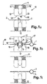
- Figure 1a illustrates a tool 10, consisting of a first tool half 11 and a second tool half 12. On each side of each tool half 11, 12 there is provided a combined ejector and rest 13 for a plate 1. The ejectors are each pre-tensioned pairwise against one another by means of a spring 14.
- Each tool half 11, 12 is equipped with a plurality of projections 15, which are best illustrated in Figure 2. Spaces 16 are formed between the projections.
- the tool halves 11, 12 are configured so that the projections 15 on the tool half 11 fit into the spaces 16 on the tool half 12, and vice versa.
- a plate 1 is inserted between the tool halves 11, 12, which plate comprises a main surface 2 and a number of side edges.
- the projections 15 of the second tool half 12 also project beyond the dividing plane 19 of the tool by the same length 1, but in the opposite direction. Therefore, an equally large amount of plate material, measured in the figured plane of Fig. 1b, is pressed out to each side of the dividing plane 19 of the tool, thereby ensuring that the plate is substantially free from tension, even after the convexities have been formed.
- the shape of the convexities 3, 4 can be adapted according to the application of the plate.
- the only condition set is that the convexities lying along the same straight line have the same length measured along the convexity from the main face of the plate on one side of the convexity to the main face of the plate on the other side of the convexity.
- all the convexities 3, 4 arranged pairwise opposite each other are of the same length measured along the convexity.
- convexities formed along different lines may be of different lengths.
- the extent of the convexities along the straight line from plate edge to plate edge and the height of arch of the convexities measured from the principal plane of the plate are of no importance and can be adjusted according to use.
- the convexities on the same line may have different cross-sectional shapes.
- the straight lines along which the convexities lie do not need to be parallel to each other, but may be at a randomly selected angle to each other.
- the row of convexities must extend from one side edge of the plate in a straight line to the other side edge of the plate.
- the plate will twist or bend to a very small degree, apart from the actual convexities, and the plate will be easy to bend into a desired shape once the convexities have been formed.
- recesses may optionally also be punched out in the plate. The recesses may be located between the convexities in one line, or they may be located between the convexities in two adjacent lines.
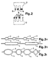
- a plate 1 which in general comprises a first side face 2a and a second side face 2b. From this plate 1, areas 3 are pressed out in a first direction, so that the areas 3 form a curved face at a distance from the first side face 2a. Other areas 4 are pressed out from the plate 1 in an opposite direction and form a second curved face at a distance from the second side face 2b, so that the areas 3 and 4 are in alternating relation in a row 5 across the plate.
- a plurality of such rows 5 can be arranged at a distance from each other, and define areas 6 between each other, which areas 6 are in the planar main portion 2 of the plate. Between each of the areas 3 and 4, openings 7 are formed for the insertion of, for example, a hook 8 (see Figure 6), bolts, thread, wires, cables, pipes and so forth.
- the alternating areas 3 and 4 are alternately formed having a short and a long length.
- the areas 3a have a longer length than the areas 3b, and likewise the areas 4a have a longer length than the areas 4b.
- the pressed-out areas 3 and 4 may have any chosen cross-sectional form, e.g., a circular cross-sectional form. With the circular cross-sectional form, it is possible to arrange hooks so as to be capable of swinging on the plate 1.
- Figure 6 shows a section of the plate 1 where the alternating areas 3 and 4 are plain to see.
- the areas are arranged in a row following a repetitive pattern: A short area 3b, a short area 4b, a long area 3a, a short area 4b, a short area 3b and a long area 4a.
- a short area 3b, a short area 4b, a long area 3a, a short area 4b, a short area 3b and a long area 4a Naturally, other patterns of alternating areas are also possible, depending upon what is to be secured to the plate.
- a plate is shown that is primarily intended as a suspension means for hooks or the like, this plate can be used in virtually any situation where it is desirable to hold together various elements.
- One example may be the fastening together of reinforcing rods for reinforcing, for instance, concrete.
- a plate may then, for example, be bent into a cylinder and held in this position by means of bars disposed substantially diametrically on the inside of the cylinder and secured in the openings 7, in the same way as the hooks 8.
- On the outside reinforcing rods can be inserted through the openings 7 along the rows 5.
- Several cylinders of this kind can be arranged along the reinforcing rods. In this way good reinforcement will be obtained for making, e.g., pillars or columns.
- the plate of the invention is therefore not limited to only the said areas of application, but can be used in any area whatsoever where it is desirable to have a tension-free plate provided with pressed-out portions in opposite directions.
Landscapes
- Mechanical Engineering (AREA)
- Engineering & Computer Science (AREA)
- Connection Of Plates (AREA)
- Shaping Metal By Deep-Drawing, Or The Like (AREA)
- Shaping Of Tube Ends By Bending Or Straightening (AREA)
- Table Devices Or Equipment (AREA)
- Food-Manufacturing Devices (AREA)
- Conveying And Assembling Of Building Elements In Situ (AREA)
- Mechanical Treatment Of Semiconductor (AREA)
- Load-Engaging Elements For Cranes (AREA)
- Laminated Bodies (AREA)
- Gripping Jigs, Holding Jigs, And Positioning Jigs (AREA)
- Lining Or Joining Of Plastics Or The Like (AREA)
Claims (7)
- Procédé pour former des convexités (3, 4) sur une grande surface d'un corps de plaque (1), tout en empêchant le corps de plaque (1) de se déformer du fait de la formation de convexités, corps de plaque (1) qui comporte une face principale (2) et une pluralité de faces latérales, ledit corps de plaque (1) étant inséré entre un outil muni de deux moitiés d'outils (11, 12) qui sont amenés ensemble et qui interagissent pour emboutir un premier ensemble de convexités (3) dans une première direction par rapport à la face principale (2) du corps de plaque (1), et un second ensemble de convexités (4) dans une seconde direction opposée par rapport à la face principale (2) du corps de plaque (1), les convexités (3, 4) étant formées le long d'une ligne droite à travers le corps de plaque (1) entre deux bords latéraux de celui-ci, caractérisé en ce qu'une pluralité de lignes munies de convexités sont formées sur le corps de plaque, en ce que pour chaque étape de formation, le corps de plaque (1) est fixé de manière ferme par l'intermédiaire d'éjecteurs agencés par paires (13) sur les deux côtés de saillies de formation de convexité (15) de chaque moitié d'outils (11, 12), les éjecteurs ayant une face (18) appuyant contre la face principale (2) du corps de plaque (1), et maintenant la face principale (2) dans son orientation dans le plan de division de l'outil, et chacune des convexités (3) du premier ensemble de convexités est emboutie vers l'extérieur par une longueur (1), mesurée à partir de la convexité (3) au niveau d'un point (20) situé sur la face principale (2) du corps de plaque (1) le long de la convexité (3) vers l'autre côté de ladite convexité (3) au niveau d'un point (21) situé sur la face principale (2) du corps de plaque (1), qui est sensiblement égale à la longueur correspondante (1) par laquelle chacune des convexités (4) du second ensemble de convexités est emboutie vers l'extérieur.
- Procédé selon la revendication 1, caractérisé en ce que des évidements sont poinçonnés dans le corps de plaque (1) en même temps que les convexités (3, 4) sont formées.
- Outil comportant une première moitié d'outil (11) et une seconde moitié d'outil (12), l'outil ayant un plan de division dans lequel les deux moitiés (11, 12) ont une pluralité de saillies (15) agencées le long d'une ligne droite, et sont séparées par une pluralité d'espaces (16), lesdites saillies (15) de la première moitié d'outil (1) s'agençant dans les espaces (16) situés sur la seconde moitié d'outil (12), et vice versa, caractérisé en ce que chacune des moitiés est munie d'éjecteurs agencés par paire (13) situés des deux côtés des saillies (15) de chaque moitié d'outils (11, 12), les éjecteurs ayant une face (18), la face (18) étant située dans le plan de division (19) de l'outil lorsque les moitiés d'outils (11, 12) sont amenées complètement ensemble, les moitiés d'outils immobilisant fermement un corps de plaque (1) entre les faces (18), de sorte que la face principale (2) du corps de plaque est maintenue dans le plan de division (19) de l'outil, et en ce que les saillies (15) de la première moitié d'outil (11) ont une longueur (1), mesurée à partir d'un point (20) situé dans le plan de division (19) de l'outil, à travers la partie supérieure de la saillie vers un point (21) situé dans le plan de division (19) sur le côté opposé de la saillie (15), qui est égale à la longueur correspondante (1) à travers les saillies (15) de la seconde moitié d'outil (12), pour faciliter la formation de convexités (3, 4) sur une grande surface du corps de plaque (1), tout en empêchant le corps de plaque (1) de se déformer du fait de la formation de convexités.
- Outil selon la revendication 3, caractérisé en ce que les éjecteurs (13) sont munis de ressorts (14), qui mettent sous tension préalable les éjecteurs (13) par paire l'un contre l'autre.
- Plaque comportant une face principale (2) et une pluralité de bords latéraux, plaque dans laquelle sont formés un premier ensemble de convexités (3) dans une première direction par rapport à la face principale (2) de la plaque (1), et un second ensemble de convexités (4) dans une seconde direction opposée par rapport à la face principale (2), les convexités (3) du premier ensemble de convexités étant d'une longueur (1), mesurée à partir d'un premier côté de la convexité (3) au niveau d'un point (20) situé sur la face principale (2) le long de la convexité (3) vers l'autre côté de ladite convexité (3) au niveau d'un point (21) situé sur la face principale (2) du corps de plaque (1), qui est sensiblement égale à la longueur correspondante (1) de chacune des convexités (4) du second ensemble de convexités, la plaque (1) étant munie de parties embouties selon un motif de répétition sur au moins une majeure partie de l'étendue de la plaque, et agencée en une pluralité de lignes, le motif de parties embouties étant constitué :ladite première zone (3) venant en butée sur la seconde zone (4), de sorte qu'une ouverture (7) est formée à travers la plaque (1) au niveau de la ligne de limite entre la première zone (3) et la seconde zone (4), ouverture (7) qui est dirigée sensiblement parallèlement à la partie plane de la plaque (2), où respectivement la première zone (3) et la seconde zone (4) sont connectées à la plaque (1) le long d'au moins une partie respectivement de la première (3) et seconde zone (4), et caractérisée en ce que le motif formé par les première et seconde zones apparaít sous la forme d'un motif de répétition identique des deux côtés de la plaque, le motif de plaque comportant des zones (3, 4) qui sont de longueurs différentes en alternance dans la direction desdites lignes.d'une première zone (3) qui forme une face incurvée faisant saillie à partir d'une première face latérale plane (2a) de la plaque,d'une seconde zone (4) qui forme une face incurvée faisant saillie à partir d'une seconde face latérale plane opposée (2b) de la plaque,
- Plaque selon la revendication 5, caractérisée en ce que les zones (3, 4) alternent selon le motif suivant :une zone courte (3b) faisant saillie à partir du premier côté (2a) de la plaque,une zone courte (4b) faisant saillie à partir du second côté opposé (2b) de la plaque,une zone longue (3a) faisant saillie à partir du premier côté (2a) de la plaque,une zone courte (4b) faisant saillie à partir du second côté opposé (2b) de la plaque,une zone courte (3b) faisant saillie à partir du premier côté (2a) de la plaque,une zone longue (4a) faisant saillie à partir du second côté opposé (2b) de la plaque.
- Plaque selon la revendication 5, combinée avec un crochet, de sorte que le motif de plaque comporte des zones (3, 4) qui sont de longueurs différentes en alternance dans la direction desdites lignes selon le motif suivant :une zone courte (4b) faisant saillie à partir du premier côté (2a) de la plaque,une zone courte (4b) faisant saillie à partir du second côté opposé (2b) de la plaque,le crochet ayant une partie de jambe devant être insérée entre des convexités desdits premier et second ensembles, ladite zone longue ayant une longueur qui est sensiblement égale à la longueur de ladite jambe, ou légèrement plus longue que celle-ci, ladite zone courte ayant une longueur qui est plus courte que la longueur de ladite jambe.
Applications Claiming Priority (3)
| Application Number | Priority Date | Filing Date | Title |
|---|---|---|---|
| NO961328 | 1996-04-01 | ||
| NO961328A NO302505B1 (no) | 1996-04-01 | 1996-04-01 | Plate og anvendelse av platen |
| PCT/NO1997/000080 WO1997036703A1 (fr) | 1996-04-01 | 1997-03-21 | Procede de formation de convexities dans un element de type plaque, outil utilise et plaque correspondante |
Publications (2)
| Publication Number | Publication Date |
|---|---|
| EP0892687A1 EP0892687A1 (fr) | 1999-01-27 |
| EP0892687B1 true EP0892687B1 (fr) | 2002-06-05 |
Family
ID=19899218
Family Applications (1)
| Application Number | Title | Priority Date | Filing Date |
|---|---|---|---|
| EP97916666A Expired - Lifetime EP0892687B1 (fr) | 1996-04-01 | 1997-03-21 | Procede de formation de convexities dans un element de type plaque, outil utilise et plaque correspondante |
Country Status (13)
| Country | Link |
|---|---|
| US (1) | US6460393B1 (fr) |
| EP (1) | EP0892687B1 (fr) |
| JP (1) | JP2000507507A (fr) |
| AT (1) | ATE218402T1 (fr) |
| AU (1) | AU712010B2 (fr) |
| CA (1) | CA2249267C (fr) |
| DE (1) | DE69713085T2 (fr) |
| DK (1) | DK0892687T3 (fr) |
| ES (1) | ES2177969T3 (fr) |
| NO (1) | NO302505B1 (fr) |
| PT (1) | PT892687E (fr) |
| TW (1) | TW327614B (fr) |
| WO (1) | WO1997036703A1 (fr) |
Families Citing this family (10)
| Publication number | Priority date | Publication date | Assignee | Title |
|---|---|---|---|---|
| NO984850L (no) | 1998-10-16 | 2000-05-10 | Sundhagen Lena | LÕsbart oppheng |
| US9708816B2 (en) | 2014-05-30 | 2017-07-18 | Sacks Industrial Corporation | Stucco lath and method of manufacture |
| US9752323B2 (en) | 2015-07-29 | 2017-09-05 | Sacks Industrial Corporation | Light-weight metal stud and method of manufacture |
| US9797142B1 (en) | 2016-09-09 | 2017-10-24 | Sacks Industrial Corporation | Lath device, assembly and method |
| EP3330657B1 (fr) | 2016-12-01 | 2020-10-28 | Modine Manufacturing Company | Lamelle d'évacuation de l'air d'un échangeur de chaleur et son procédé de fabrication |
| JP6596466B2 (ja) * | 2017-06-06 | 2019-10-23 | 株式会社Subaru | 車両用パネル構造 |
| JP7055465B2 (ja) | 2017-08-14 | 2022-04-18 | ストラクタ ワイヤー ユーエルシー | 可変長金属スタッド |
| US11351593B2 (en) | 2018-09-14 | 2022-06-07 | Structa Wire Ulc | Expanded metal formed using rotary blades and rotary blades to form such |
| USD949442S1 (en) * | 2019-04-23 | 2022-04-19 | Epic Metals Corporation | Roofing deck |
| CN222012451U (zh) * | 2023-12-14 | 2024-11-15 | 广东欧富隆自动货架科技有限公司 | 一种层架支撑滑轨 |
Family Cites Families (13)
| Publication number | Priority date | Publication date | Assignee | Title |
|---|---|---|---|---|
| US493791A (en) * | 1893-03-21 | Hermann sciiurig | ||
| GB510877A (en) * | 1938-02-07 | 1939-08-08 | Arthur William Trippas | Improvements relating to the manufacture of perforated metal for gaskets or other purposes |
| US2797817A (en) * | 1955-04-01 | 1957-07-02 | Vaco Products Co | Display and storage rack |
| US2784769A (en) * | 1955-06-06 | 1957-03-12 | Sturgis Posture Chair Company | Chair construction |
| US3062570A (en) * | 1959-11-04 | 1962-11-06 | Schwartz Metal Company Inc | Connector |
| US3111977A (en) * | 1961-03-29 | 1963-11-26 | Kruger Cornelius Johannes | Method and means for producing holes in metallic members |
| US3208505A (en) * | 1962-01-03 | 1965-09-28 | Robertshaw Controls Co | Holders for pilot burners, thermocouples and the like |
| US3851846A (en) | 1973-06-04 | 1974-12-03 | Westinghouse Electric Corp | Support and leveling arrangement |
| US4453364A (en) * | 1980-05-27 | 1984-06-12 | Ting Raymond M L | Corrugated steel decking section |
| US4522860A (en) * | 1983-01-10 | 1985-06-11 | Metalcore Limited | Material for reinforcing core in a structure |
| US4510786A (en) * | 1983-05-19 | 1985-04-16 | The Langenau Manufacturing Company | Method and apparatus of making double reverse corrugated material |
| GB8411943D0 (en) * | 1984-05-10 | 1984-06-13 | Fether K B | Bracket and post assembly |
| DK163026C (da) * | 1989-10-09 | 1992-06-01 | Concept Interioer A S | Skinne, isaer vaegskinne, fremgangsmaade til fremstilling heraf samt vaerktoej hertil |
-
1996
- 1996-04-01 NO NO961328A patent/NO302505B1/no not_active IP Right Cessation
-
1997
- 1997-03-21 WO PCT/NO1997/000080 patent/WO1997036703A1/fr not_active Ceased
- 1997-03-21 DE DE69713085T patent/DE69713085T2/de not_active Expired - Fee Related
- 1997-03-21 CA CA002249267A patent/CA2249267C/fr not_active Expired - Fee Related
- 1997-03-21 AT AT97916666T patent/ATE218402T1/de not_active IP Right Cessation
- 1997-03-21 ES ES97916666T patent/ES2177969T3/es not_active Expired - Lifetime
- 1997-03-21 US US09/142,804 patent/US6460393B1/en not_active Expired - Fee Related
- 1997-03-21 DK DK97916666T patent/DK0892687T3/da active
- 1997-03-21 EP EP97916666A patent/EP0892687B1/fr not_active Expired - Lifetime
- 1997-03-21 AU AU25230/97A patent/AU712010B2/en not_active Ceased
- 1997-03-21 JP JP9535161A patent/JP2000507507A/ja not_active Abandoned
- 1997-03-21 PT PT97916666T patent/PT892687E/pt unknown
- 1997-04-30 TW TW086105736A patent/TW327614B/zh active
Also Published As
| Publication number | Publication date |
|---|---|
| US20020124622A1 (en) | 2002-09-12 |
| WO1997036703A1 (fr) | 1997-10-09 |
| AU712010B2 (en) | 1999-10-28 |
| CA2249267C (fr) | 2001-12-11 |
| TW327614B (en) | 1998-03-01 |
| JP2000507507A (ja) | 2000-06-20 |
| NO961328D0 (no) | 1996-04-01 |
| DK0892687T3 (da) | 2003-04-14 |
| US6460393B1 (en) | 2002-10-08 |
| NO302505B1 (no) | 1998-03-16 |
| DE69713085D1 (de) | 2002-07-11 |
| ATE218402T1 (de) | 2002-06-15 |
| NO961328L (no) | 1997-10-02 |
| ES2177969T3 (es) | 2002-12-16 |
| PT892687E (pt) | 2002-10-31 |
| EP0892687A1 (fr) | 1999-01-27 |
| CA2249267A1 (fr) | 1997-10-09 |
| DE69713085T2 (de) | 2002-11-07 |
| AU2523097A (en) | 1997-10-22 |
Similar Documents
| Publication | Publication Date | Title |
|---|---|---|
| US6460393B1 (en) | Method for forming bucklings in a plate member, tool and plate | |
| US4471596A (en) | Vault grid | |
| US5579624A (en) | Profile bar for the attachment of flat objects | |
| ES2646626T3 (es) | Clip para moldura perimetral | |
| US11891804B2 (en) | Ceiling system | |
| CZ299185B6 (cs) | Závesný systém pro suchou zed | |
| US11608635B2 (en) | Support member for ceiling system | |
| EP1308577A3 (fr) | Système de plancher avec une pluralité de panneaux | |
| GB2387397A (en) | Cushion block for supporting e.g. floorboards | |
| EP1427081A2 (fr) | Dispositif d'attache de supports de cable en fils sur des sections de suport . | |
| CA2056109A1 (fr) | Profiles en te courbes pour plafonds suspendus | |
| CA2169183A1 (fr) | Suspente de tuyau en feuillard | |
| ITTO20010460A1 (it) | Dispositivo di illuminazione a luminanza controllata. | |
| US6446406B1 (en) | Direct attached grid | |
| IL104101A (en) | Members for reinforcing supporting and tying steel bars for reinforced concrete | |
| CA2171140A1 (fr) | Connecteur | |
| WO1988002072A1 (fr) | Procede d'ancrage d'un dispositif de fixation ou de suspension et dispositif de realisation dudit procede | |
| US6763642B2 (en) | Grid for a suspended ceiling | |
| EP1439921B1 (fr) | Procede et outil pour former des convexites | |
| KR200274780Y1 (ko) | 전선관 고정구 | |
| ITMI20020330U1 (it) | Dispositivo perfezionato per l'allacciamento di cavi fili metallici esimili | |
| US20050115192A1 (en) | Curved structural member | |
| EP4077824B1 (fr) | Connecteur à pince pour la liaison de deux poteaux | |
| US20060272254A1 (en) | Wall element | |
| RU96101659A (ru) | Устройство для изготовления зигзагообразного гофра и способ его работы |
Legal Events
| Date | Code | Title | Description |
|---|---|---|---|
| PUAI | Public reference made under article 153(3) epc to a published international application that has entered the european phase |
Free format text: ORIGINAL CODE: 0009012 |
|
| 17P | Request for examination filed |
Effective date: 19980929 |
|
| AK | Designated contracting states |
Kind code of ref document: A1 Designated state(s): AT BE CH DE DK ES FI FR GB GR IE IT LI LU MC NL PT SE |
|
| 17Q | First examination report despatched |
Effective date: 20000322 |
|
| GRAG | Despatch of communication of intention to grant |
Free format text: ORIGINAL CODE: EPIDOS AGRA |
|
| GRAG | Despatch of communication of intention to grant |
Free format text: ORIGINAL CODE: EPIDOS AGRA |
|
| GRAH | Despatch of communication of intention to grant a patent |
Free format text: ORIGINAL CODE: EPIDOS IGRA |
|
| GRAH | Despatch of communication of intention to grant a patent |
Free format text: ORIGINAL CODE: EPIDOS IGRA |
|
| GRAA | (expected) grant |
Free format text: ORIGINAL CODE: 0009210 |
|
| AK | Designated contracting states |
Kind code of ref document: B1 Designated state(s): AT BE CH DE DK ES FI FR GB GR IE IT LI LU MC NL PT SE |
|
| REF | Corresponds to: |
Ref document number: 218402 Country of ref document: AT Date of ref document: 20020615 Kind code of ref document: T |
|
| REG | Reference to a national code |
Ref country code: GB Ref legal event code: FG4D |
|
| REG | Reference to a national code |
Ref country code: CH Ref legal event code: EP |
|
| REG | Reference to a national code |
Ref country code: IE Ref legal event code: FG4D |
|
| REF | Corresponds to: |
Ref document number: 69713085 Country of ref document: DE Date of ref document: 20020711 |
|
| REG | Reference to a national code |
Ref country code: CH Ref legal event code: NV Representative=s name: PATENTANWAELTE SCHAAD, BALASS, MENZL & PARTNER AG |
|
| ET | Fr: translation filed | ||
| REG | Reference to a national code |
Ref country code: PT Ref legal event code: SC4A Free format text: AVAILABILITY OF NATIONAL TRANSLATION Effective date: 20020821 |
|
| REG | Reference to a national code |
Ref country code: GR Ref legal event code: EP Ref document number: 20020402890 Country of ref document: GR |
|
| REG | Reference to a national code |
Ref country code: ES Ref legal event code: FG2A Ref document number: 2177969 Country of ref document: ES Kind code of ref document: T3 |
|
| PG25 | Lapsed in a contracting state [announced via postgrant information from national office to epo] |
Ref country code: LU Free format text: LAPSE BECAUSE OF NON-PAYMENT OF DUE FEES Effective date: 20030321 |
|
| PG25 | Lapsed in a contracting state [announced via postgrant information from national office to epo] |
Ref country code: MC Free format text: LAPSE BECAUSE OF NON-PAYMENT OF DUE FEES Effective date: 20030331 |
|
| REG | Reference to a national code |
Ref country code: DK Ref legal event code: T3 |
|
| PLBE | No opposition filed within time limit |
Free format text: ORIGINAL CODE: 0009261 |
|
| STAA | Information on the status of an ep patent application or granted ep patent |
Free format text: STATUS: NO OPPOSITION FILED WITHIN TIME LIMIT |
|
| 26N | No opposition filed |
Effective date: 20030306 |
|
| PGFP | Annual fee paid to national office [announced via postgrant information from national office to epo] |
Ref country code: DK Payment date: 20040123 Year of fee payment: 8 |
|
| PGFP | Annual fee paid to national office [announced via postgrant information from national office to epo] |
Ref country code: FR Payment date: 20040227 Year of fee payment: 8 |
|
| PGFP | Annual fee paid to national office [announced via postgrant information from national office to epo] |
Ref country code: NL Payment date: 20040311 Year of fee payment: 8 Ref country code: GB Payment date: 20040311 Year of fee payment: 8 |
|
| PGFP | Annual fee paid to national office [announced via postgrant information from national office to epo] |
Ref country code: CH Payment date: 20040312 Year of fee payment: 8 |
|
| PGFP | Annual fee paid to national office [announced via postgrant information from national office to epo] |
Ref country code: FI Payment date: 20040315 Year of fee payment: 8 Ref country code: PT Payment date: 20040315 Year of fee payment: 8 |
|
| PGFP | Annual fee paid to national office [announced via postgrant information from national office to epo] |
Ref country code: IE Payment date: 20040319 Year of fee payment: 8 |
|
| PGFP | Annual fee paid to national office [announced via postgrant information from national office to epo] |
Ref country code: ES Payment date: 20040324 Year of fee payment: 8 Ref country code: AT Payment date: 20040324 Year of fee payment: 8 |
|
| PGFP | Annual fee paid to national office [announced via postgrant information from national office to epo] |
Ref country code: DE Payment date: 20040325 Year of fee payment: 8 Ref country code: SE Payment date: 20040325 Year of fee payment: 8 |
|
| PGFP | Annual fee paid to national office [announced via postgrant information from national office to epo] |
Ref country code: GR Payment date: 20040329 Year of fee payment: 8 |
|
| PGFP | Annual fee paid to national office [announced via postgrant information from national office to epo] |
Ref country code: BE Payment date: 20040330 Year of fee payment: 8 |
|
| PG25 | Lapsed in a contracting state [announced via postgrant information from national office to epo] |
Ref country code: IT Free format text: LAPSE BECAUSE OF NON-PAYMENT OF DUE FEES Effective date: 20050321 Ref country code: IE Free format text: LAPSE BECAUSE OF NON-PAYMENT OF DUE FEES Effective date: 20050321 Ref country code: GB Free format text: LAPSE BECAUSE OF NON-PAYMENT OF DUE FEES Effective date: 20050321 Ref country code: AT Free format text: LAPSE BECAUSE OF NON-PAYMENT OF DUE FEES Effective date: 20050321 |
|
| PG25 | Lapsed in a contracting state [announced via postgrant information from national office to epo] |
Ref country code: SE Free format text: LAPSE BECAUSE OF NON-PAYMENT OF DUE FEES Effective date: 20050322 Ref country code: ES Free format text: LAPSE BECAUSE OF NON-PAYMENT OF DUE FEES Effective date: 20050322 |
|
| PG25 | Lapsed in a contracting state [announced via postgrant information from national office to epo] |
Ref country code: LI Free format text: LAPSE BECAUSE OF NON-PAYMENT OF DUE FEES Effective date: 20050331 Ref country code: DK Free format text: LAPSE BECAUSE OF NON-PAYMENT OF DUE FEES Effective date: 20050331 Ref country code: CH Free format text: LAPSE BECAUSE OF NON-PAYMENT OF DUE FEES Effective date: 20050331 Ref country code: BE Free format text: LAPSE BECAUSE OF NON-PAYMENT OF DUE FEES Effective date: 20050331 |
|
| PG25 | Lapsed in a contracting state [announced via postgrant information from national office to epo] |
Ref country code: PT Free format text: LAPSE BECAUSE OF NON-PAYMENT OF DUE FEES Effective date: 20050921 |
|
| BERE | Be: lapsed |
Owner name: *SUNDHAGEN LENA Effective date: 20050331 |
|
| PG25 | Lapsed in a contracting state [announced via postgrant information from national office to epo] |
Ref country code: NL Free format text: LAPSE BECAUSE OF NON-PAYMENT OF DUE FEES Effective date: 20051001 Ref country code: DE Free format text: LAPSE BECAUSE OF NON-PAYMENT OF DUE FEES Effective date: 20051001 |
|
| PG25 | Lapsed in a contracting state [announced via postgrant information from national office to epo] |
Ref country code: GR Free format text: LAPSE BECAUSE OF NON-PAYMENT OF DUE FEES Effective date: 20051004 |
|
| EUG | Se: european patent has lapsed | ||
| REG | Reference to a national code |
Ref country code: CH Ref legal event code: PL |
|
| GBPC | Gb: european patent ceased through non-payment of renewal fee |
Effective date: 20050321 |
|
| PG25 | Lapsed in a contracting state [announced via postgrant information from national office to epo] |
Ref country code: FR Free format text: LAPSE BECAUSE OF NON-PAYMENT OF DUE FEES Effective date: 20051130 |
|
| NLV4 | Nl: lapsed or anulled due to non-payment of the annual fee |
Effective date: 20051001 |
|
| REG | Reference to a national code |
Ref country code: DK Ref legal event code: EBP |
|
| REG | Reference to a national code |
Ref country code: IE Ref legal event code: MM4A |
|
| REG | Reference to a national code |
Ref country code: FR Ref legal event code: ST Effective date: 20051130 |
|
| REG | Reference to a national code |
Ref country code: ES Ref legal event code: FD2A Effective date: 20050322 |
|
| BERE | Be: lapsed |
Owner name: *SUNDHAGEN LENA Effective date: 20050331 |