EP0892998B1 - Arbeitsgerät mit einem elektromotor als antrieb - Google Patents
Arbeitsgerät mit einem elektromotor als antrieb Download PDFInfo
- Publication number
- EP0892998B1 EP0892998B1 EP97917293A EP97917293A EP0892998B1 EP 0892998 B1 EP0892998 B1 EP 0892998B1 EP 97917293 A EP97917293 A EP 97917293A EP 97917293 A EP97917293 A EP 97917293A EP 0892998 B1 EP0892998 B1 EP 0892998B1
- Authority
- EP
- European Patent Office
- Prior art keywords
- plug
- bow
- battery
- appliance according
- charging
- Prior art date
- Legal status (The legal status is an assumption and is not a legal conclusion. Google has not performed a legal analysis and makes no representation as to the accuracy of the status listed.)
- Expired - Lifetime
Links
Images


Classifications
-
- H—ELECTRICITY
- H02—GENERATION; CONVERSION OR DISTRIBUTION OF ELECTRIC POWER
- H02K—DYNAMO-ELECTRIC MACHINES
- H02K11/00—Structural association of dynamo-electric machines with electric components or with devices for shielding, monitoring or protection
- H02K11/0094—Structural association with other electrical or electronic devices
-
- A—HUMAN NECESSITIES
- A01—AGRICULTURE; FORESTRY; ANIMAL HUSBANDRY; HUNTING; TRAPPING; FISHING
- A01D—HARVESTING; MOWING
- A01D69/00—Driving mechanisms or parts thereof for harvesters or mowers
- A01D69/02—Driving mechanisms or parts thereof for harvesters or mowers electric
-
- H—ELECTRICITY
- H02—GENERATION; CONVERSION OR DISTRIBUTION OF ELECTRIC POWER
- H02K—DYNAMO-ELECTRIC MACHINES
- H02K5/00—Casings; Enclosures; Supports
- H02K5/04—Casings or enclosures characterised by the shape, form or construction thereof
- H02K5/22—Auxiliary parts of casings not covered by groups H02K5/06-H02K5/20, e.g. shaped to form connection boxes or terminal boxes
- H02K5/225—Terminal boxes or connection arrangements
Definitions
- the invention relates to an implement, in particular on a garden tool, e.g. a lawn mower, with an electric motor as a drive and a replaceable, rechargeable Battery connected to electrical connections via a connector can be connected to the motor connections.
- a garden tool e.g. a lawn mower
- an electric motor as a drive
- a replaceable, rechargeable Battery connected to electrical connections via a connector can be connected to the motor connections.
- a battery pack which is equipped with plug contacts that are in counter connections the electric craft machine or a charger are.
- plug contacts and the counter connections each part of a plug-in coupling, part the connection means from contact pins protruding in the direction of insertion consists.
- Such a battery pack for electrical hand machine tools is known from DE 94 21 382.
- the electrical connection to the drive motor or Charger-producing plug contacts still form-locking connections provided that rule out polarity reversal.
- known accumulator package is when assembling the coupling parts inevitably the electrical connection is established.
- the electrical plug contacts of the battery pack at least provided electrical insulation on one side, whereby the short-circuit security should be improved.
- Lawnmowers with interchangeable battery packs are known where connections are arranged on the outside of the battery pack are when inserting the battery pack into a Battery routing of the device housing inevitably with the Contact the existing connections.
- a safety switch is a common feature on the lawn mower chassis near the battery Switch designed as a key switch.
- To the Charging the battery are connections in the device housing Insert a connector provided over the one Charger provides power to charge the battery. The battery can also be removed from the working device via the charger can be charged, which can be connected to the battery connections is.
- the invention has for its object to provide an implement to provide a safety plug contact connection device, in which the electrical contact connection between the Connections of a replaceable battery pack and motor connections or charger connections not just by inserting them of the battery pack in the implement can be used, but additional plug functions are required.
- the task is solved by the totality of the Characteristic part of claim 1 specified features. This is only done by plugging in the clip connector electrical connection possible, and this electrical connection It can only be closed using the bow connector when the battery pack is properly inserted into the implement so that the motor connections and the battery pack connections ready for exposure parallel to each other at the same height for the bracket plug.
- This bow connector causes one reliable electrical isolation between battery and motor, and only after removing the bow connector, i.e. after galvanic isolation, the battery pack can be out the corresponding guide of the device housing be, so that switching on the motor with certainty Replacing the battery pack is excluded.
- the find the same bow plug as a charging plug whereby this charging bracket connector to a multi-pin connector of the Battery pack is set and the connection to the charger manufactures.
- the charger or the connecting line with a connector corresponding to the connector bracket connector equipped on the multi-pin connector of the battery pack or charger can be plugged in and these are electrically connected to one another connects while connecting after the drive motor of the device is interrupted. Corresponding positive locking connections prevent incorrect polarity.
- the invention ensures that the stirrup connector arrangement can be used for the three functions, namely for Safety power cut, for power connection after Drive motor and for the power connection between the battery pack and charger.
- plug contacts for the multi-pin plug and the bow connector can conventional spring contacts and Contact sockets are used so that the plug connection is inexpensive to manufacture.
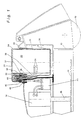
- the chassis 12 of a lawnmower carried by wheels 10 carries a DC electric motor 14, the vertical one Output shaft 16 rotating in a horizontal plane Knife 18 carries.
- a rechargeable battery 20 is made in two parts Lower part 22 and cover 24 housed existing battery case. This consists of battery 20, lower part 22 and cover 24 existing battery pack is in guides 26 of the chassis used a vertical removal of the battery pack and allow the battery case to be inserted into the chassis, with bevels a guide to the end position ensure in the form of the battery pack is supported on all sides.
- the cover 24 has on its lower, the motor facing end a bracket 28 for the protective sleeve 30th of a multi-pin plug, the two arranged parallel to each other Has spring contacts 32 with the battery terminals 34 are connected via cable 36.
- a further multipole plug consisting of protective sleeve 40 and Spring contacts 42, fixed. If the battery pack 20, 22, 24 is inserted into the lawn mower chassis, then the Spring contact pairs 32 and 42 parallel to each other and in the same Altitude.
- the spring contacts 32 and 42 of the two pairs are through one Bow connector 44 connectable.
- This bow connector has a Plug housing on that on the protective sleeves 30 and 40 of Battery pack or the device housing can be placed, wherein a suitable positive connection 46 on the stirrup connector housing or the polarity of the multi-pin plug is excluded.
- Plug 54 is connected to a charger 59 via a charging cable 56 connected.
- the charging plug 54 is equipped with contact blades 58, the one with the spring contacts 32 of the multipole plug 30 interact.
- Through the positive connection 46 ensures that the charging plug 54 only in the correct Angular position can be plugged in, in which the negative poles or the plus poles are connected.
- An electric one Connection after the drive motor is excluded.
- an electrical switch 60 housed.
- the invention has been described using a lawnmower however, this can also be used for other garden tools, e.g. Hedge trimmers or scarifiers, but also with others Find tools outside the garden sector.
- the Bow connector two pairs of contact springs attached at the same height. However, this could be done with appropriate training the bow connector also at different altitudes be arranged.
- the vertical insertion direction is for reasons preference for ease of use. Remain reserved but should also be a different direction.
Landscapes
- Engineering & Computer Science (AREA)
- Power Engineering (AREA)
- Life Sciences & Earth Sciences (AREA)
- Environmental Sciences (AREA)
- Battery Mounting, Suspending (AREA)
- Harvester Elements (AREA)
- Portable Nailing Machines And Staplers (AREA)
- Secondary Cells (AREA)
Description
- 10
- Räder
- 12
- Chassis
- 14
- Elektromotor
- 16
- Abtriebswelle
- 18
- Messer
- 20
- Batterie )
- 22
- Unterteil ) Batteriepaket
- 24
- Deckel )
- 26
- Führungen
- 28
- Halterung
- 30
- Schutzhülse
- 32
- Federkontakte
- 34
- Batterieanschlüsse
- 36
- Kabel
- 38
- Isolierstück
- 40
- Schutzhülse
- 42
- Federkontakte
- 44
- Bügelstecker
- 46
- Formschlußführung
- 48
- Formschlußverbindung
- 50
- Kontaktmesser
- 52
- Kabelbrücken
- 54
- Ladestecker
- 56
- Ladekabel
- 58
- Kontaktmesser
- 59
- Ladegerät
- 60
- Schaltelektrik
Claims (10)
- Arbeitsgerät mit einem Elektromotor (14) als Antrieb und einem Batteriepaket (20, 22, 24) mit einer aufladbaren Batterie (20), deren Anschlüsse (34) über eine Steckvorrichtung mit den Motoranschlüssen verbindbar sind, wobei die Steckvorrichtung zwei parallel zueinander angeordnete, mit den Batterieanschlüssen bzw. den Motoranschlüssen in Verbindung stehende mehrpolige Stecker und einen abziehbaren VerbindungsBügelstecker (44) für diese Stecker aufweist,
dadurch gekennzeichnet, daß der eine Stecker im Chassis (12) des Gerätes und der andere Stecker an dem Batteriepaket (20, 22, 24) festgelegt ist, das aus dem Chassis (12) entnehmbar und in dieses über eine Führung (26) einsetzbar ist. - Arbeitsgerät nach Anspruch 1,
dadurch gekennzeichnet, daß die Steckachse des Bügelsteckers (44) parallel zu der Führung (26) für das Batteriepaket (20, 22, 24) verläuft. - Arbeitsgerät nach Anspruch 2,
dadurch gekennzeichnet, daß die Stecker Federkontakte (32, 42) aufweisen, die von Schutzhülsen (30, 40) getragen werden, die im Deckel (24) des Batteriepaketes bzw. in einem im Gerätechassis eingesetzten Isolierstück (38) festgelegt sind. - Arbeitsgerät nach einem der Ansprüche 1 bis 3,
dadurch gekennzeichnet, daß die Führung (26) eine Formschlußverbindung (48) aufweist, die die gegenseitige Lage der Stecker im eingesetzten Zustand der Batterie festlegt. - Arbeitsgerät nach einem der Ansprüche 1 bis 4,
dadurch gekennzeichnet, daß der Bügelstecker (44) parallel zur Einsatzrichtung des Batteriepaketes (20, 22, 24) steckbar ist. - Arbeitsgerät nach einem der Ansprüche 1 bis 5,
gekennzeichnet durch einen dem Bügelstecker (44) entsprechenden Ladestecker (54), der über ein Ladekabel (56) mit einem Ladegerät (59) verbunden ist und Kontaktmesser (58) als Ladeanschlußkontakte aufweist. - Arbeitsgerät nach einem der Ansprüche 1 bis 6,
dadurch gekennzeichnet, daß Bügelstecker (44) und Ladestecker (54) eine Formschlußführung (46) aufweisen. - Arbeitsgerät nach einem der Ansprüche 1 bis 7,
dadurch gekennzeichnet, daß die Federkontakte (32, 42) vollständig von den Schutzhülsen (30, 40) umschlossen sind und mit Kontaktmessern (50, 58) des Bügelsteckers (44) bzw. des Ladesteckers (54) zusammenwirken. - Arbeitsgerät nach einem der Ansprüche 1 bis 8,
dadurch gekennzeichnet, daß es als Rasenmäher ausgebildet ist. - Arbeitsgerät nach einem der Ansprüche 1 bis 9,
dadurch gekennzeichnet, daß zwischen den Motoranschlüssen und den geräteseitigen Federkontakten (42) eine Schaltelektrik (60) angeordnet ist.
Applications Claiming Priority (3)
| Application Number | Priority Date | Filing Date | Title |
|---|---|---|---|
| DE19614199 | 1996-04-10 | ||
| DE19614199A DE19614199C1 (de) | 1996-04-10 | 1996-04-10 | Arbeitsgerät mit einem batteriebetriebenen Elektromotor |
| PCT/EP1997/001707 WO1997038468A1 (de) | 1996-04-10 | 1997-04-05 | Arbeitsgerät mit einem elektromotor als antrieb |
Publications (2)
| Publication Number | Publication Date |
|---|---|
| EP0892998A1 EP0892998A1 (de) | 1999-01-27 |
| EP0892998B1 true EP0892998B1 (de) | 1999-09-15 |
Family
ID=7790917
Family Applications (1)
| Application Number | Title | Priority Date | Filing Date |
|---|---|---|---|
| EP97917293A Expired - Lifetime EP0892998B1 (de) | 1996-04-10 | 1997-04-05 | Arbeitsgerät mit einem elektromotor als antrieb |
Country Status (5)
| Country | Link |
|---|---|
| US (1) | US6195970B1 (de) |
| EP (1) | EP0892998B1 (de) |
| AT (1) | ATE184734T1 (de) |
| DE (2) | DE19614199C1 (de) |
| WO (1) | WO1997038468A1 (de) |
Families Citing this family (12)
| Publication number | Priority date | Publication date | Assignee | Title |
|---|---|---|---|---|
| GB9717093D0 (en) * | 1997-08-12 | 1997-10-15 | Bosch Gmbh Robert | Improvements in or relating to vegetation cutters |
| GB2338392A (en) * | 1998-06-16 | 1999-12-22 | Black & Decker Inc | Switch for battery powered lawn mower. |
| DE19850147A1 (de) * | 1998-10-30 | 2000-07-06 | Otfried Bauer | Bewuchsschneidemaschine |
| US6921287B2 (en) * | 2003-09-02 | 2005-07-26 | Phoenixtec Power Co., Ltd. | Exchangeable module for an electric system |
| US7568538B2 (en) * | 2005-02-02 | 2009-08-04 | Mattel, Inc. | Children's ride-on vehicle charging assemblies with back feed protection |
| US7728534B2 (en) * | 2006-10-17 | 2010-06-01 | Mtd Products Inc | Hybrid electric lawnmower |
| WO2008048615A2 (en) | 2006-10-17 | 2008-04-24 | Desa Ip, Llc | Hybrid electric device |
| US20080120955A1 (en) * | 2006-10-17 | 2008-05-29 | Lucas Delbert R | Hybrid electric lawnmower |
| US8732896B2 (en) | 2006-10-17 | 2014-05-27 | Mtd Products Inc | Hybrid electric cleaning device |
| US7479754B2 (en) * | 2006-10-17 | 2009-01-20 | Desa Ip Llc | Hybrid electric lawnmower |
| US8076873B1 (en) | 2007-06-01 | 2011-12-13 | Mtd Products Inc | Hybrid outdoor power equipment |
| JP5694065B2 (ja) * | 2011-06-14 | 2015-04-01 | 株式会社マキタ | 電動芝刈機 |
Family Cites Families (11)
| Publication number | Priority date | Publication date | Assignee | Title |
|---|---|---|---|---|
| US3493915A (en) * | 1968-05-17 | 1970-02-03 | Lyall Electric | Safety plug for electrical devices |
| US3696593A (en) * | 1968-09-04 | 1972-10-10 | Toro Mfg Corp | Electric start for mowers |
| US3581480A (en) * | 1969-09-30 | 1971-06-01 | Black & Decker Mfg Co | Multiple-function receptacle and interconnecting plugs therefor |
| US5085043A (en) * | 1990-06-01 | 1992-02-04 | Black & Decker Inc. | Electro-mechanical interlock and module system for lawn mower or other electrical device |
| JP2512784Y2 (ja) * | 1990-09-20 | 1996-10-02 | 川崎重工業株式会社 | 内装ユニットの配線構造 |
| CA2089994C (en) * | 1992-04-17 | 1997-08-05 | Pamela M. St. John | Automatic backup battery connection |
| US5301494A (en) * | 1992-07-24 | 1994-04-12 | Ryobi Motor Products Corp. | Recharging system for a battery operated tool having an on-board transformer |
| US5606851A (en) * | 1993-09-22 | 1997-03-04 | Briggs & Stratton Corporation | Battery-powered lawn cutting system |
| US5449301A (en) * | 1993-11-17 | 1995-09-12 | Berg Technology, Inc. | Shunt connector |
| DE4406879A1 (de) | 1994-03-03 | 1995-09-07 | Bosch Gmbh Robert | Akkumulatorpaket für Elektrohandwerkzeugmaschinen |
| DE9421382U1 (de) * | 1994-03-03 | 1995-09-28 | Robert Bosch Gmbh, 70469 Stuttgart | Akkumulatorpaket für Elektrohandwerkzeugmaschinen |
-
1996
- 1996-04-10 DE DE19614199A patent/DE19614199C1/de not_active Expired - Fee Related
-
1997
- 1997-04-05 EP EP97917293A patent/EP0892998B1/de not_active Expired - Lifetime
- 1997-04-05 DE DE59700446T patent/DE59700446D1/de not_active Expired - Fee Related
- 1997-04-05 WO PCT/EP1997/001707 patent/WO1997038468A1/de not_active Ceased
- 1997-04-05 US US09/155,910 patent/US6195970B1/en not_active Expired - Fee Related
- 1997-04-05 AT AT97917293T patent/ATE184734T1/de not_active IP Right Cessation
Also Published As
| Publication number | Publication date |
|---|---|
| WO1997038468A1 (de) | 1997-10-16 |
| EP0892998A1 (de) | 1999-01-27 |
| US6195970B1 (en) | 2001-03-06 |
| DE19614199C1 (de) | 1997-10-23 |
| DE59700446D1 (de) | 1999-10-21 |
| ATE184734T1 (de) | 1999-10-15 |
Similar Documents
| Publication | Publication Date | Title |
|---|---|---|
| DE69321477T2 (de) | Vorrichtung zum wiederaufladen von batteriebetriebenen elektrischen geräte | |
| DE69900212T2 (de) | Elektrischer Schalter | |
| EP0372026B1 (de) | Motorbetriebene grasschere | |
| DE69936838T2 (de) | Leistungssteckverbinder für kinderfahrzeug | |
| EP0892998B1 (de) | Arbeitsgerät mit einem elektromotor als antrieb | |
| EP3154106B1 (de) | Elektrohandwerkzeuggerät | |
| DE112013006397B4 (de) | Manueller Service-Trennschalter für Batteriesysteme | |
| DE68923304T2 (de) | Batterielader und Batteriegehäuse. | |
| EP0485784B1 (de) | Ladeeinrichtung für wiederaufladbare Batterien | |
| DE202017006868U1 (de) | Batteriepack, Elektrogerät, das den Batteriepack verwendet, und Elektrogerätesystem | |
| EP0038376A2 (de) | Batteriebetriebenes Elektro-Handgerät | |
| DE29914147U1 (de) | Elektrisches Steckdosenbauteil mit Überhitzungs- und Überlastungsschutz | |
| DE10251706B4 (de) | Schutzvorrichtung zum Unterbrechen einer Stromversorgung | |
| DE10224752A1 (de) | Elektrisches Verbindungsgehäuse | |
| WO2019063212A1 (de) | Akkupack | |
| DE202009002787U1 (de) | Akkupack | |
| DE1051163B (de) | Elektrischer Rasierapparat | |
| DE102020200317A1 (de) | Akkupack für eine Handwerkzeugmaschine, Handwerkzeugmaschine und Ladegerät | |
| EP0863522B1 (de) | Notabschaltvorrichtung, insbesondere bei Elektro-Flurförderzeugen zum Trennen der Verbindung zwischen Motor oder dessen Steuereinheit und den Antriebsbatterien für diesen | |
| DE102007031859A1 (de) | Akkumulator | |
| EP3678216A1 (de) | Akkupack und garten- und/oder forstbearbeitunsgssystem | |
| DE19814810C1 (de) | Vernetzungsbaustein | |
| DE202017006869U1 (de) | Batteriepack, Elektrogerät, das den Batteriepack verwendet, und Elektrogerätesystem | |
| EP4402767A1 (de) | Schnittstellenmodul zum betreiben eines elektrischen verbrauchers mit zumindest einem wechselbaren energiespeicher sowie verfahren zur ansteuerung des elektrischen verbrauchers mittels des schnittstellenmoduls | |
| WO2022111958A1 (de) | Wechselakkupack mit zumindest einem schaltelement zur unterbrechung bzw. ermöglichung eines lade- oder entladestroms |
Legal Events
| Date | Code | Title | Description |
|---|---|---|---|
| PUAI | Public reference made under article 153(3) epc to a published international application that has entered the european phase |
Free format text: ORIGINAL CODE: 0009012 |
|
| 17P | Request for examination filed |
Effective date: 19980922 |
|
| AK | Designated contracting states |
Kind code of ref document: A1 Designated state(s): AT BE CH DE FI FR GB IT LI NL |
|
| GRAG | Despatch of communication of intention to grant |
Free format text: ORIGINAL CODE: EPIDOS AGRA |
|
| GRAG | Despatch of communication of intention to grant |
Free format text: ORIGINAL CODE: EPIDOS AGRA |
|
| GRAH | Despatch of communication of intention to grant a patent |
Free format text: ORIGINAL CODE: EPIDOS IGRA |
|
| 17Q | First examination report despatched |
Effective date: 19990301 |
|
| GRAH | Despatch of communication of intention to grant a patent |
Free format text: ORIGINAL CODE: EPIDOS IGRA |
|
| GRAA | (expected) grant |
Free format text: ORIGINAL CODE: 0009210 |
|
| ITF | It: translation for a ep patent filed | ||
| AK | Designated contracting states |
Kind code of ref document: B1 Designated state(s): AT BE CH DE FI FR GB IT LI NL |
|
| PG25 | Lapsed in a contracting state [announced via postgrant information from national office to epo] |
Ref country code: FI Free format text: LAPSE BECAUSE OF NON-PAYMENT OF DUE FEES Effective date: 19990915 |
|
| REF | Corresponds to: |
Ref document number: 184734 Country of ref document: AT Date of ref document: 19991015 Kind code of ref document: T |
|
| REG | Reference to a national code |
Ref country code: CH Ref legal event code: EP |
|
| GBT | Gb: translation of ep patent filed (gb section 77(6)(a)/1977) |
Effective date: 19990916 |
|
| REF | Corresponds to: |
Ref document number: 59700446 Country of ref document: DE Date of ref document: 19991021 |
|
| ET | Fr: translation filed | ||
| PLBE | No opposition filed within time limit |
Free format text: ORIGINAL CODE: 0009261 |
|
| STAA | Information on the status of an ep patent application or granted ep patent |
Free format text: STATUS: NO OPPOSITION FILED WITHIN TIME LIMIT |
|
| 26N | No opposition filed | ||
| PG25 | Lapsed in a contracting state [announced via postgrant information from national office to epo] |
Ref country code: LI Free format text: LAPSE BECAUSE OF NON-PAYMENT OF DUE FEES Effective date: 20010504 Ref country code: CH Free format text: LAPSE BECAUSE OF NON-PAYMENT OF DUE FEES Effective date: 20010504 |
|
| REG | Reference to a national code |
Ref country code: CH Ref legal event code: PL |
|
| REG | Reference to a national code |
Ref country code: GB Ref legal event code: IF02 |
|
| PGFP | Annual fee paid to national office [announced via postgrant information from national office to epo] |
Ref country code: DE Payment date: 20050310 Year of fee payment: 9 |
|
| PGFP | Annual fee paid to national office [announced via postgrant information from national office to epo] |
Ref country code: AT Payment date: 20050315 Year of fee payment: 9 |
|
| PGFP | Annual fee paid to national office [announced via postgrant information from national office to epo] |
Ref country code: NL Payment date: 20050316 Year of fee payment: 9 |
|
| PGFP | Annual fee paid to national office [announced via postgrant information from national office to epo] |
Ref country code: FR Payment date: 20050317 Year of fee payment: 9 |
|
| PGFP | Annual fee paid to national office [announced via postgrant information from national office to epo] |
Ref country code: BE Payment date: 20050321 Year of fee payment: 9 |
|
| PGFP | Annual fee paid to national office [announced via postgrant information from national office to epo] |
Ref country code: GB Payment date: 20050404 Year of fee payment: 9 |
|
| PG25 | Lapsed in a contracting state [announced via postgrant information from national office to epo] |
Ref country code: GB Free format text: LAPSE BECAUSE OF NON-PAYMENT OF DUE FEES Effective date: 20060405 Ref country code: AT Free format text: LAPSE BECAUSE OF NON-PAYMENT OF DUE FEES Effective date: 20060405 |
|
| PG25 | Lapsed in a contracting state [announced via postgrant information from national office to epo] |
Ref country code: BE Free format text: LAPSE BECAUSE OF NON-PAYMENT OF DUE FEES Effective date: 20060430 |
|
| PGFP | Annual fee paid to national office [announced via postgrant information from national office to epo] |
Ref country code: IT Payment date: 20060430 Year of fee payment: 10 |
|
| PG25 | Lapsed in a contracting state [announced via postgrant information from national office to epo] |
Ref country code: NL Free format text: LAPSE BECAUSE OF NON-PAYMENT OF DUE FEES Effective date: 20061101 Ref country code: DE Free format text: LAPSE BECAUSE OF NON-PAYMENT OF DUE FEES Effective date: 20061101 |
|
| GBPC | Gb: european patent ceased through non-payment of renewal fee |
Effective date: 20060405 |
|
| NLV4 | Nl: lapsed or anulled due to non-payment of the annual fee |
Effective date: 20061101 |
|
| REG | Reference to a national code |
Ref country code: FR Ref legal event code: ST Effective date: 20061230 |
|
| BERE | Be: lapsed |
Owner name: *WOLF-GERATE G.M.B.H. VERTRIEBSGESELLSCHAFT K.G. Effective date: 20060430 |
|
| PG25 | Lapsed in a contracting state [announced via postgrant information from national office to epo] |
Ref country code: FR Free format text: LAPSE BECAUSE OF NON-PAYMENT OF DUE FEES Effective date: 20060502 |
|
| PG25 | Lapsed in a contracting state [announced via postgrant information from national office to epo] |
Ref country code: IT Free format text: LAPSE BECAUSE OF NON-PAYMENT OF DUE FEES Effective date: 20070405 |