EP0893038B1 - Perfectionnements relatifs a des appareils menagers electriques de chauffage de liquides et a leurs organes de commande - Google Patents
Perfectionnements relatifs a des appareils menagers electriques de chauffage de liquides et a leurs organes de commande Download PDFInfo
- Publication number
- EP0893038B1 EP0893038B1 EP97916522A EP97916522A EP0893038B1 EP 0893038 B1 EP0893038 B1 EP 0893038B1 EP 97916522 A EP97916522 A EP 97916522A EP 97916522 A EP97916522 A EP 97916522A EP 0893038 B1 EP0893038 B1 EP 0893038B1
- Authority
- EP
- European Patent Office
- Prior art keywords
- heating element
- combination
- mounting
- electrical connection
- appliance
- Prior art date
- Legal status (The legal status is an assumption and is not a legal conclusion. Google has not performed a legal analysis and makes no representation as to the accuracy of the status listed.)
- Expired - Lifetime
Links
- 238000010438 heat treatment Methods 0.000 title claims description 58
- 239000007788 liquid Substances 0.000 title claims description 7
- 230000015572 biosynthetic process Effects 0.000 claims description 11
- 238000005755 formation reaction Methods 0.000 claims description 11
- 238000005485 electric heating Methods 0.000 claims description 2
- 229910052751 metal Inorganic materials 0.000 claims description 2
- 239000002184 metal Substances 0.000 claims description 2
- 230000001419 dependent effect Effects 0.000 claims 1
- 230000001012 protector Effects 0.000 description 5
- XLYOFNOQVPJJNP-UHFFFAOYSA-N water Substances O XLYOFNOQVPJJNP-UHFFFAOYSA-N 0.000 description 5
- 230000000295 complement effect Effects 0.000 description 2
- 230000000694 effects Effects 0.000 description 2
- 238000004519 manufacturing process Methods 0.000 description 2
- 239000004411 aluminium Substances 0.000 description 1
- 229910052782 aluminium Inorganic materials 0.000 description 1
- XAGFODPZIPBFFR-UHFFFAOYSA-N aluminium Chemical compound [Al] XAGFODPZIPBFFR-UHFFFAOYSA-N 0.000 description 1
- 230000002950 deficient Effects 0.000 description 1
- 238000011161 development Methods 0.000 description 1
- 230000018109 developmental process Effects 0.000 description 1
- 238000003754 machining Methods 0.000 description 1
- 238000012986 modification Methods 0.000 description 1
- 230000004048 modification Effects 0.000 description 1
- 230000001681 protective effect Effects 0.000 description 1
Images





Classifications
-
- H—ELECTRICITY
- H05—ELECTRIC TECHNIQUES NOT OTHERWISE PROVIDED FOR
- H05B—ELECTRIC HEATING; ELECTRIC LIGHT SOURCES NOT OTHERWISE PROVIDED FOR; CIRCUIT ARRANGEMENTS FOR ELECTRIC LIGHT SOURCES, IN GENERAL
- H05B1/00—Details of electric heating devices
- H05B1/02—Automatic switching arrangements specially adapted to apparatus ; Control of heating devices
- H05B1/0202—Switches
- H05B1/0213—Switches using bimetallic elements
-
- A—HUMAN NECESSITIES
- A47—FURNITURE; DOMESTIC ARTICLES OR APPLIANCES; COFFEE MILLS; SPICE MILLS; SUCTION CLEANERS IN GENERAL
- A47J—KITCHEN EQUIPMENT; COFFEE MILLS; SPICE MILLS; APPARATUS FOR MAKING BEVERAGES
- A47J27/00—Cooking-vessels
- A47J27/21—Water-boiling vessels, e.g. kettles
- A47J27/21166—Constructional details or accessories
-
- H—ELECTRICITY
- H05—ELECTRIC TECHNIQUES NOT OTHERWISE PROVIDED FOR
- H05B—ELECTRIC HEATING; ELECTRIC LIGHT SOURCES NOT OTHERWISE PROVIDED FOR; CIRCUIT ARRANGEMENTS FOR ELECTRIC LIGHT SOURCES, IN GENERAL
- H05B3/00—Ohmic-resistance heating
- H05B3/78—Heating arrangements specially adapted for immersion heating
- H05B3/82—Fixedly-mounted immersion heaters
Definitions
- This invention concerns improvements relating to electrically powered liquid heating appliances and controls therefor.
- the invention may be applied to liquid heating appliances such as electric kettles, hot water jugs, urns, pans, laboratory equipment etc., and will be described in the following with particular reference to electric kettles and hot water jugs, though it is to be well understood that the invention is not limited to such appliances.
- an element overtemperature protector is a device which is adapted to sense the occurrence in the heating element of an electric water heating appliance or the like of an overtemperature condition and to switch-off the supply of power to the element.
- Cordless connection systems are employed with so-called cordless electrical appliances in which power is supplied to the appliance proper through a base unit connected to the mains supply, the appliance proper and the base unit having complementary parts of an electrical connector system adapted to mate for the supply of power through the base unit to the appliance proper when the latter is set down upon the base unit.
- the invention of British patent application GB-A-2 306 801 abovementioned is particularly concerned with tolerance problems which can arise in the fitting of protective and connector devices to water heating appliances in the course of their manufacture.
- the bracket(s) serve(s) furthermore for the mounting of a bottom cover of the vessel in such a manner that the fixing of the bottom cover of the vessel causes the planar heating element to be drawn into the open bottom of the vessel and to seal against a flange provided in the bottom of the vessel.
- planar electric heating elements can be found in WO-A-9 418 807 and GB-A-2 283 156.
- the present invention concerns further developments that we have made in relation to the attachment of element overtemperature protector devices and/or cordless connector parts to planar heating elements in electrically powered water heating vessels.
- bracket and stud mounting arrangement described in British patent application GB-A 2 307 602 is modified to provide redundant mounting facilities useful in the event (however unlikely) that an element overtemperature protection device and/or cordless connector system part affixed to the element proves to be faulty or fails in use.
- the present invention proposes to at least duplicate such mounting studs and apertures so that, in the event of failure of a device attached by the bracket(s) and studs to the element, the failed device can be removed by machining off the already utilized studs and there will be other intact studs available for the fitting of a replacement device.
- the present invention provides a pair of such mounting studs and a pair of apertures in the mounting bracket(s).
- a pair of apertures in the mounting bracket(s) there could instead be an elongate aperture serving the same purpose.
- a laterally elongate formation could be provided to the same effect, such formation being adapted to be received in a complementary slot in the mounting bracket and enabling riveting of the bracket to the underside of the element by deformation of the formation selectively at a plurality of different locations along its length.
- Figs 1A-1C shown therein is an exemplary arrangement for mounting an element overtemperature protection control 1 to the underside of a planar electrical heating element 2 by means of a mounting bracket 3.
- the control 1 is an X2 control manufactured by us and is a modified form of the control that is described in GB-A-2194099 with reference to Figs 3A-3C thereof.
- the planar heating element 2 is based upon a conventional Bleckmann element and comprises a heating element proper 4 clenched to an aluminium plate 5.
- the mounting bracket 3 is shown in more detail in Figs 7A-7D.
- the heating element base plate 5 is formed with six post-like irreversibly deformable mounting studs 6 depending from the undersurface thereof.
- the mounting bracket 3 comprises an elongate flat metal base 8 having holes 9 formed therein for receiving the-upper row of four in-line mounting studs 6, and formed with mounting limbs 10 extending from and elevated above the base 8 for attachment to the element overtemperature protection control 1 and with an earth or ground connection tab terminal 11.
- Assembly of the illustrated arrangement is effected by first securing the limbs 10 of the bracket 3 to the element overtemperature control 1 by rivetting so as to form a sub-assembly which is then offered up to the underside of the heating element.
- the four holes 9 in the base 8 of the mounting bracket register with the upper row of the four posts 6 that depend from the undersurface of the heating element 2, and the other two posts 6 register with corresponding holes in a fixing bracket 12 formed as an integral part of the control 1.
- Two of the four in-line posts 6 can then be peened so as to deform and effectively rivet the mounting bracket 3 to the underside of the heating element, and similarly with one of the other two posts so as to secure the other side of the control 1.
- the already utilized posts 6 can be machined off so as to enable the control to be replaced, and three intact posts will still be available for attachment of the replacement control at the same location.
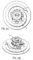
- FIGS 2A and 2B show an arrangement wherein an element overtemperature protection control 1 substantially as abovedescribed is affixed to a planar heating element 2 as abovedescribed with reference to Figure 1A in combination with a cordless connector system part 20, a bracket 21 as shown in Figures 6A-6D being utilized.
- the cordless connector system part 20 is described in British patent application GB-A-2 306 801 aforementioned and is manufactured and marketed by us as the CP7 cordless appliance connector inlet; this cordless connector system advantageously provides for connection between a cordless appliance proper and its base within any rotational relative orientation of the appliance proper and its base and is the subject of our British patent application no. 9504233.9 (GB-A-2285716).
- the bracket 21 of Figures 6A-6D has a base part 8 with holes 9 and offset limbs 10 just as in the mounting bracket 3 of Figures 7A-7D, and these perform the same functions as they perform in the mounting bracket 3.
- the bracket 21 has long legs 22 which extend from the ends of the base 8 and terminate in mounting feet 23 which, as can be seen from Figure 2B, serve for mounting the cordless connector system part 20 above (as viewed) the element overtemperature protection control 1.
- the legs 22 are slotted as shown so as to enhance their flexibility and the feet 23 have elongated spire nut formations 24 providing for lateral adjustability of the mounting of the connector part 20.
- the flexibility of the legs 22, coupled with the adjustability of the spire nut formations 24 provides compliance in three dimensional space of the mounting position of the connector part 20 which enables appliance manufacturing tolerances easily to be accommodated.
- Figures 3A, 3B and 3C show an alternative arrangement to that of Figures 2A and 2B wherein the element overtemperature protection control 1 and the cordless connector system part 20 are mounted in side-by-side relation rather than one above the other.
- This is enabled by virtue of the heating element proper 4 being disposed more about the periphery of the element plate 5, as shown in Figure 3A, than it is in the heating element of Figure 1A, this arrangement freeing up more space centrally of the element plate 5 and enabling the side-by-side arrangement of control 1 and connector part 20 to be accommodated.
- the control 1 and connector part 20 mounted side-by-side, also in the arrangement shown the current carrying terminals of the connector part 20 plug into the control 1 in the manner described in our British patent application GB-A-2 306 801.
- FIG 3A shows the underside of the heating element and it will be seen also that the mounting studs 6 are differently arranged as compared to the heating element of Figure 1A, the arrangement shown ensuring the accessibility of the studs once the sub-assembly of control 1, connector part 20 and mounting bracket 30 has been fitted thereto.
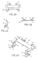
- the mounting bracket 30 is shown in detail in Figures 4A-4D and, as with the brackets hereinbefore described, comprises a base 8 with mounting holes 9 and, offset therefrom, limbs 10 enabling mounting of the overtemperature protection control 1.
- the bracket 30 has forward extensions 31 from the ends of base 8 and legs 32 depend from the extensions 31 and terminate in feet 33 provided with elongate spire nut formations 34, the legs 32 being slotted for enhanced flexibility in the manner of the legs 22 of the mounting bracket of Figures 6A-6D.
- the mounting posts provide redundancy so that a failed or ineffective control 1 and/or cordless connector system part 20 can be replaced without having to discard the heating element.
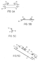
- Figures 5A-5D show an alternative mounting bracket 50 adapted for use with the heating element of Figure 3A when only an element overtemperature protection control 1 is required to be fitted.
- the arrangements hereinbefore described advantageously enable replacement of an element overtemperature protection control and/or a cordless connector part without the element having to be discarded.
- the attachment of an appliance bottom cover can be arranged to pull the planar heating element down into the bottom of the vessel and effect its mounting by virtue of pulling upon the mounting bracket.
- Alternative ways of securing the heating element could however be utilized.
- the arrangement can be such that the control and the connector system part plug into one another as taught in our British patent application GB-A-2 306 801 Alternatively they can be arranged to be interconnected by means of flying leads.
Landscapes
- Engineering & Computer Science (AREA)
- Food Science & Technology (AREA)
- Cookers (AREA)
- Central Heating Systems (AREA)
Claims (20)
- Elément de chauffage électrique plan (2) pour un appareil ménager électrique de chauffage de liquide, ledit élément de chauffage ayant des moyens (6) déformables de manière irréversible permettant la fixation à l'élément de chauffage (2) d'une commande (1) de protection contre la surchauffe de l'élément et/ou d'une partie (20) d'un système de connexion électrique, ledit élément de chauffage étant agencé par ailleurs de telle sorte que cette commande (1) et/ou cette partie (20) du système de connexion fixées à l'élément puissent être retirées si elles deviennent inopérantes et puissent être remplacées sans devoir mettre l'élément au rebut.
- Elément de chauffage selon la revendication 1, dans lequel lesdits moyens (6) déformables de manière irréversible comprennent des saillies (6) susceptibles d'être utilisées pour fixer la commande (1) et/ou la partie (20) du système de connexion et, en outre, lesdites saillies déformables de manière irréversible sont destinées à être utilisées pour fixer une commande de substitution et/ou une partie de substitution du système de connexion à l'élément, après que la commande et/ou la partie du système de connexion fixées et inopérantes ont été retirées.
- Elément de chauffage selon la revendication 2, dans lequel lesdites saillies (6) comprennent des goujons qui sont déformables à la manière d'un rivet.
- Elément de chauffage selon la revendication 2, dans lequel lesdites saillies sont allongées latéralement de manière à assurer une déformation sélective dans une pluralité de positions.
- Elément de chauffage selon la revendication 2 ou 3 ou 4, dans lequel les saillies (6) font partie intégrante de l'élément de chauffage plan (2).
- Elément de chauffage selon l'une quelconque des revendications précédentes, comprenant une plaque de métal (5) ayant un élément de chauffage à résistance électrique (4) fixé à une de ses surfaces.
- Elément de chauffage selon l'une quelconque des revendications précédentes en combinaison avec un support de montage (3, 21; 30; 50) fixé ou susceptible d'être fixé à l'élément, ledit support de montage servant à la fixation à l'élément de chauffage (2) d'une commande (1) de protection contre la surchauffe de l'élément et/ou d'une partie d'un système de connexion électrique (20), comme précitées.
- Combinaison selon la revendication 7, dans laquelle le support de montage (3; 50) n'est destiné qu'au montage d'une commande (1) de protection contre la surchauffe de l'élément comme précitée sur l'élément de chauffage (2).
- Combinaison selon la revendication 7, dans laquelle le support de montage (21; 30) est destiné au montage à la fois d'une commande (1) de protection contre la surchauffe de l'élément comme précité et/ou d'une partie d'un système de connexion électrique (20) comme précitée sur l'élément de chauffage (2).
- Combinaison selon la revendication 9, dans laquelle le support de montage (30) est agencé pour le montage de la commande (1) de protection contre la surchauffe de l'élément et la partie du système de connexion électrique (20) en relation côte à côte.
- Combinaison selon la revendication 9, dans laquelle le support de montage (21) est agencé pour le montage de la commande (1) de protection contre la surchauffe de l'élément et la partie du système de connexion électrique (20) en relation l'un au-dessus de l'autre.
- Combinaison selon la revendication 10 ou 11, dans laquelle le support de montage (21; 30) est agencé pour conformer dans la position de montage d'au moins la partie du système de connexion électrique (20).
- Combinaison selon l'une quelconque des revendications 7 à 12, comprenant par ailleurs une commande (1) de protection contre la surchauffe de l'élément comme précitée.
- Combinaison selon l'une quelconque des revendications 7 à 13, comprenant en outre une partie d'un système de connexion électrique (20) comme précitée.
- Combinaison selon la revendication 14, dans laquelle ladite partie d'un système de connexion électrique (20) est la partie d'entrée du connecteur d'un appareil ménager pour un système de connexion électrique à fil.
- Combinaison selon la revendication 14, dans laquelle ladite partie d'un système de connexion électrique (20) est la partie d'entrée du connecteur d'un appareil ménager pour un système de connexion électrique sans fil.
- Combinaison selon la revendication 16, dans laquelle ledit système de connexion électrique sans fil est agencé pour permettre l'alimentation énergétique de l'élément de chauffage par l'intermédiaire du système de connecteur sensiblement quelle que soit l'orientation relative en rotation des deux parties du système de connecteur électrique sans fil.
- Appareil ménager électrique de chauffage de liquide, dans lequel est ajusté un élément de chauffage selon l'une quelconque des revendications 1 à 6 ou une combinaison selon l'une quelconque des revendications 7 à 17.
- Appareil ménager selon la revendication 18, dans lequel la fixation d'un couvercle inférieur à l'appareil ménager sert à fixer l'élément de chauffage (2) dans l'appareil ménager.
- Appareil ménager selon la revendication 19, dans la mesure où elle dépend de la revendication 7, dans lequel ledit couvercle inférieur est fixé audit support ou à un composant qui est fixé audit support.
Applications Claiming Priority (3)
| Application Number | Priority Date | Filing Date | Title |
|---|---|---|---|
| GB9607413 | 1996-04-10 | ||
| GB9607413A GB2312142B (en) | 1996-04-10 | 1996-04-10 | Improvements relating to electrically powered liquid heating appliances and controls therefor |
| PCT/GB1997/000984 WO1997038557A1 (fr) | 1996-04-10 | 1997-04-09 | Perfectionnements relatifs a des appareils menagers electriques de chauffage de liquides et a leurs organes de commande |
Publications (2)
| Publication Number | Publication Date |
|---|---|
| EP0893038A1 EP0893038A1 (fr) | 1999-01-27 |
| EP0893038B1 true EP0893038B1 (fr) | 2001-06-27 |
Family
ID=10791810
Family Applications (1)
| Application Number | Title | Priority Date | Filing Date |
|---|---|---|---|
| EP97916522A Expired - Lifetime EP0893038B1 (fr) | 1996-04-10 | 1997-04-09 | Perfectionnements relatifs a des appareils menagers electriques de chauffage de liquides et a leurs organes de commande |
Country Status (6)
| Country | Link |
|---|---|
| EP (1) | EP0893038B1 (fr) |
| CN (1) | CN1138453C (fr) |
| AU (1) | AU2514497A (fr) |
| DE (1) | DE69705397T2 (fr) |
| GB (1) | GB2312142B (fr) |
| WO (1) | WO1997038557A1 (fr) |
Families Citing this family (3)
| Publication number | Priority date | Publication date | Assignee | Title |
|---|---|---|---|---|
| GB2342685B (en) * | 1998-10-13 | 2002-11-06 | Otter Controls Ltd | Improvements relating to the control of electric heating elements |
| GB2364890A (en) | 2000-07-25 | 2002-02-13 | Otter Controls Ltd | Securing planar heating element in liquid heating vessel |
| GB0302537D0 (en) * | 2003-02-04 | 2003-03-12 | Strix Ltd | Electric heaters |
Family Cites Families (6)
| Publication number | Priority date | Publication date | Assignee | Title |
|---|---|---|---|---|
| NL84262B (fr) * | 1936-09-23 | |||
| DE2932026A1 (de) * | 1979-08-07 | 1981-02-26 | Bosch Siemens Hausgeraete | Elektrische heizeinrichtung mit einem heizelement aus kaltleitermaterial |
| GB2092869B (en) * | 1981-02-10 | 1984-11-28 | Micropore International Ltd | An electric cooker |
| GB9302965D0 (en) * | 1993-02-15 | 1993-03-31 | Strix Ltd | Immersion heaters |
| GB2283156B (en) * | 1993-10-21 | 1997-09-17 | Otter Controls Ltd | Improvements relating to electrical heating elements and controls therefor |
| DE4403638C2 (de) * | 1994-02-05 | 1997-02-13 | Volz Abc Elektrogeraete | Gerät zum Erhitzen von Flüssigkeiten |
-
1996
- 1996-04-10 GB GB9607413A patent/GB2312142B/en not_active Revoked
-
1997
- 1997-04-09 WO PCT/GB1997/000984 patent/WO1997038557A1/fr not_active Ceased
- 1997-04-09 CN CNB971953481A patent/CN1138453C/zh not_active Expired - Fee Related
- 1997-04-09 AU AU25144/97A patent/AU2514497A/en not_active Abandoned
- 1997-04-09 DE DE69705397T patent/DE69705397T2/de not_active Expired - Fee Related
- 1997-04-09 EP EP97916522A patent/EP0893038B1/fr not_active Expired - Lifetime
Also Published As
| Publication number | Publication date |
|---|---|
| GB2312142B (en) | 2000-09-20 |
| AU2514497A (en) | 1997-10-29 |
| DE69705397D1 (de) | 2001-08-02 |
| CN1138453C (zh) | 2004-02-11 |
| GB2312142A (en) | 1997-10-15 |
| HK1018569A1 (en) | 1999-12-24 |
| EP0893038A1 (fr) | 1999-01-27 |
| GB9607413D0 (en) | 1996-06-12 |
| WO1997038557A1 (fr) | 1997-10-16 |
| DE69705397T2 (de) | 2001-10-11 |
| CN1221550A (zh) | 1999-06-30 |
Similar Documents
| Publication | Publication Date | Title |
|---|---|---|
| US6638076B2 (en) | Plug/socket assembly | |
| US20030192877A1 (en) | Method and apparatus for mounting a heater thermostat and temperature sensitive fuse | |
| US4588851A (en) | Thermostat cover | |
| TW413944B (en) | Mounting construction of a fuse for a circuit board | |
| EP0984714B1 (fr) | Element de chauffage electrique | |
| EP0893038A1 (fr) | Perfectionnements relatifs a des appareils menagers electriques de chauffage de liquides et a leurs organes de commande | |
| JP5208171B2 (ja) | 通電端子、および通電端子用アダプタ | |
| GB2315204A (en) | A kettle containing a removable planar heating element | |
| US4543445A (en) | Thermostat cover | |
| HK1018569B (en) | Improvements relating to electrically powered liquid heating appliances and controls therefor | |
| WO1997019627A9 (fr) | Ameliorations relatives aux appareils de chauffage de liquide electriques et systemes de securite correspondants | |
| CN108895521A (zh) | 一种电热膜取暖器及该取暖器的组装方法 | |
| WO1997019627A1 (fr) | Ameliorations relatives aux appareils de chauffage de liquide electriques et systemes de securite correspondants | |
| CN219953738U (zh) | 一种加热泵盖及加热泵 | |
| JPH07302679A (ja) | 電気ヒータのハウジング | |
| EP0869699A2 (fr) | Assemblage d'un élément électrique | |
| JP7564364B2 (ja) | 電気ケトル | |
| CN209845331U (zh) | 加热装置及具有该加热装置的泵 | |
| GB2342685A (en) | Twist-tab fastening, eg for electrical devices | |
| CN216357425U (zh) | 水输出装置、净水装置和水加热装置 | |
| CN220958562U (zh) | 手柄防触电结构及辐热炉 | |
| JP2025079563A (ja) | 電気機器 | |
| GB2564566A (en) | Powering and fastening a light emitting diode or chip-on-board component to a heatsink | |
| CN112243302B (zh) | 电控板组件、电加热器具及电加热装置 | |
| US20120125402A1 (en) | Solar cell mounting system |
Legal Events
| Date | Code | Title | Description |
|---|---|---|---|
| PUAI | Public reference made under article 153(3) epc to a published international application that has entered the european phase |
Free format text: ORIGINAL CODE: 0009012 |
|
| 17P | Request for examination filed |
Effective date: 19981028 |
|
| AK | Designated contracting states |
Kind code of ref document: A1 Designated state(s): DE FR GB IT |
|
| 17Q | First examination report despatched |
Effective date: 19990122 |
|
| GRAG | Despatch of communication of intention to grant |
Free format text: ORIGINAL CODE: EPIDOS AGRA |
|
| 17Q | First examination report despatched |
Effective date: 19990122 |
|
| GRAG | Despatch of communication of intention to grant |
Free format text: ORIGINAL CODE: EPIDOS AGRA |
|
| GRAG | Despatch of communication of intention to grant |
Free format text: ORIGINAL CODE: EPIDOS AGRA |
|
| GRAH | Despatch of communication of intention to grant a patent |
Free format text: ORIGINAL CODE: EPIDOS IGRA |
|
| GRAH | Despatch of communication of intention to grant a patent |
Free format text: ORIGINAL CODE: EPIDOS IGRA |
|
| GRAA | (expected) grant |
Free format text: ORIGINAL CODE: 0009210 |
|
| AK | Designated contracting states |
Kind code of ref document: B1 Designated state(s): DE FR GB IT |
|
| REF | Corresponds to: |
Ref document number: 69705397 Country of ref document: DE Date of ref document: 20010802 |
|
| ET | Fr: translation filed | ||
| ITF | It: translation for a ep patent filed | ||
| REG | Reference to a national code |
Ref country code: GB Ref legal event code: IF02 |
|
| PLBE | No opposition filed within time limit |
Free format text: ORIGINAL CODE: 0009261 |
|
| STAA | Information on the status of an ep patent application or granted ep patent |
Free format text: STATUS: NO OPPOSITION FILED WITHIN TIME LIMIT |
|
| 26N | No opposition filed | ||
| PG25 | Lapsed in a contracting state [announced via postgrant information from national office to epo] |
Ref country code: DE Free format text: LAPSE BECAUSE OF NON-PAYMENT OF DUE FEES Effective date: 20021101 |
|
| PG25 | Lapsed in a contracting state [announced via postgrant information from national office to epo] |
Ref country code: FR Free format text: LAPSE BECAUSE OF NON-PAYMENT OF DUE FEES Effective date: 20021231 |
|
| REG | Reference to a national code |
Ref country code: FR Ref legal event code: ST |
|
| PG25 | Lapsed in a contracting state [announced via postgrant information from national office to epo] |
Ref country code: IT Free format text: LAPSE BECAUSE OF NON-PAYMENT OF DUE FEES Effective date: 20050409 |
|
| PGFP | Annual fee paid to national office [announced via postgrant information from national office to epo] |
Ref country code: GB Payment date: 20100426 Year of fee payment: 14 |
|
| GBPC | Gb: european patent ceased through non-payment of renewal fee |
Effective date: 20110409 |
|
| PG25 | Lapsed in a contracting state [announced via postgrant information from national office to epo] |
Ref country code: GB Free format text: LAPSE BECAUSE OF NON-PAYMENT OF DUE FEES Effective date: 20110409 |