EP0893060B1 - Four pour le chauffage d'aliments - Google Patents
Four pour le chauffage d'aliments Download PDFInfo
- Publication number
- EP0893060B1 EP0893060B1 EP98401611A EP98401611A EP0893060B1 EP 0893060 B1 EP0893060 B1 EP 0893060B1 EP 98401611 A EP98401611 A EP 98401611A EP 98401611 A EP98401611 A EP 98401611A EP 0893060 B1 EP0893060 B1 EP 0893060B1
- Authority
- EP
- European Patent Office
- Prior art keywords
- air
- rack
- space
- lateral
- carcass
- Prior art date
- Legal status (The legal status is an assumption and is not a legal conclusion. Google has not performed a legal analysis and makes no representation as to the accuracy of the status listed.)
- Expired - Lifetime
Links
- 238000010438 heat treatment Methods 0.000 title claims description 13
- 238000009792 diffusion process Methods 0.000 claims description 5
- 238000010792 warming Methods 0.000 claims 1
- 238000007664 blowing Methods 0.000 description 21
- 238000012550 audit Methods 0.000 description 2
- 230000002093 peripheral effect Effects 0.000 description 2
- 238000010411 cooking Methods 0.000 description 1
- 244000045947 parasite Species 0.000 description 1
- 238000004064 recycling Methods 0.000 description 1
- 238000003303 reheating Methods 0.000 description 1
- 238000010257 thawing Methods 0.000 description 1
Images


Classifications
-
- A—HUMAN NECESSITIES
- A21—BAKING; EDIBLE DOUGHS
- A21B—BAKERS' OVENS; MACHINES OR EQUIPMENT FOR BAKING
- A21B1/00—Bakers' ovens
- A21B1/02—Bakers' ovens characterised by the heating arrangements
- A21B1/24—Ovens heated by media flowing therethrough
- A21B1/26—Ovens heated by media flowing therethrough by hot air
-
- F—MECHANICAL ENGINEERING; LIGHTING; HEATING; WEAPONS; BLASTING
- F24—HEATING; RANGES; VENTILATING
- F24C—DOMESTIC STOVES OR RANGES ; DETAILS OF DOMESTIC STOVES OR RANGES, OF GENERAL APPLICATION
- F24C15/00—Details
- F24C15/32—Arrangements of ducts for hot gases, e.g. in or around baking ovens
- F24C15/322—Arrangements of ducts for hot gases, e.g. in or around baking ovens with forced circulation
Definitions
- the present invention relates to an oven for heating of food.
- the oven of this invention is particularly suitable for defrosting, reheating and / or cooking precooked dishes on board aircraft.
- the air blown by the blowing machine and heated by said heating means forms two parallel flows, which are respectively blown towards the front in the two side spaces and then enter the front of the rack. They are sucked centrally in said rack by said blowing machine, returning rearward. Only a small fraction of the air blown through the machine passes transversely inside the rack by the perforations of its side walls so avoid air pockets.
- the longitudinally median part of said rack receives the two hot streams and is therefore more heated only the side parts of said rack, which does not receive only one of the two streams.
- others flow of hot blown air enters the rack through its upper and lower parts, adding their heating to that of the previous flows.
- FR 2 535 036 describes a hot air recycling oven of complex structure, the principle is based on alternating air circulation in two opposite directions.
- the object of the present invention is to remedy these drawbacks, and it relates to an oven of the type mentioned above, in which the temperature is uniform, whatever or the location of the food inside said rack.
- the oven of the type mentioned above is remarkable in that said means for guiding the air blown by said blowing machine and heated, direct said air only to said first space lateral and in that said blowing machine sucks up said air in said second lateral space.
- the blown air forms a single flow circulating in a only sense inside said oven.
- This unique flow blown in said first lateral space by said blowing machine, enters said rack through the wall corresponding side of the rack, the perforations of said wall dividing said flow into a plurality of currents uniformly heating the interior of said rack, then said currents pass through each other's perforations side wall of said rack for reconstituting said flow unique in said second lateral space, from where it is sucked by said blowing machine.
- a temperature is thus obtained uniform inside said oven.
- said means for guiding the blown air by the blowing machine have a diffuser, open towards said first lateral space to distribute evenly the air blown into it and prohibit said blown air to move towards said second lateral space.
- converging guide means addressing, on suction central of said blowing machine, the air circulating in said second lateral space.
- said diffuser and said converging guide means extend over the entire height of said lateral spaces.
- said box has strips longitudinal inside the side walls of said box.
- longitudinal bosses are provided in the side walls of said box so as to ensure homogeneous air distribution and guidance in said areas lateral spaces.
- two vertical lips each integral a side wall of said rack and substantially at an angle right in relation to it are provided at the end of the rack.
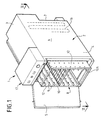
- Figure 1 is a perspective view of an example of realization of an oven according to the invention.
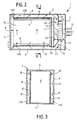
- Figure 2 is a top view, along the section plane II-II of Figure 1, of the oven according to the invention.
- Figure 3 is a cross section along the line III-III of Figure 2, of the oven of Figure 1.
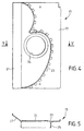
- Figure 4 is an elevational view of the diffuser.
- FIG. 5 is a section along the line V-V in FIG. 4.
- Figure 6 is an elevational view of the guide means converging.
- Figure 7 is a section along line VII-VII of the figure 6.
- Figure 8 is an exploded perspective view of the assembly diffuser-converging-blower guide means.
- the means of guiding 15 of the air blown by the blowing machine 14 direct said air only to said first lateral space 13A and the blowing machine 14 sucks said air into said second lateral space 13B, the air following the indicated path by the arrows in figure 2.
- longitudinal bosses 19 in the walls side 6 of the casing 2 provide air guidance in the lateral spaces 13A, 13B for a homogeneous distribution between the top and bottom of the cabinet.
- the means of guiding 15 of the air blown by the blowing machine 14 have a diffuser, extending over the entire height of the first lateral space 13A and open towards the said first lateral space to distribute the blown air evenly in this one and prohibit said blown air from moving towards the second lateral space 13B.
- the furnace 1 also includes converging guide means 20 extending over the entire height of the second space lateral 13B and addressing, to the central aspiration of the blowing machine 14, the air circulating in said second lateral space.
- lips 26 and 27 joined together, respectively, plates 21 and 22 and forming an angle with them, prohibit any air circulation between the first and second lateral spaces 13A, 13B at the rear of the rack 8.
Landscapes
- Engineering & Computer Science (AREA)
- Life Sciences & Earth Sciences (AREA)
- Food Science & Technology (AREA)
- Chemical & Material Sciences (AREA)
- Combustion & Propulsion (AREA)
- Mechanical Engineering (AREA)
- General Engineering & Computer Science (AREA)
- Baking, Grill, Roasting (AREA)
- Electric Stoves And Ranges (AREA)
- Devices For Warming Or Keeping Food Or Tableware Hot (AREA)
- Cold Air Circulating Systems And Constructional Details In Refrigerators (AREA)
Description
- un caisson délimitant une enceinte de chauffage et pourvu, outre d'un plafond et d'un plancher, d'une porte d'accès avant, de deux parois latérales opposées et d'une paroi arrière ;
- un râtelier servant d'étagères à des supports (plateaux, grilles, etc...) sur lesquels sont placés lesdits aliments et pourvu de deux parois latérales perforées opposées, ledit râtelier étant disposé à l'intérieur dudit caisson de façon à créer deux espaces latéraux opposés (ci-après désignés respectivement par premier et second espaces latéraux) entre lesdites parois latérales dudit râtelier et lesdites parois latérales dudit caisson ;
- une machine soufflante à aspiration centrale et à soufflage périphérique, montée sur ladite paroi arrière dudit caisson ;
- des moyens de guidage de l'air soufflé par ladite machine soufflante pour introduire latéralement cet air soufflé entre ledit râtelier et ledit caisson ; et
- des moyens de chauffage dudit air soufflé par ladite machine soufflante.
- deux plaques parallèles entre elles et à la paroi arrière dudit caisson ;
- une lame au moins approximativement en forme de V, emprisonnée entre lesdites plaques et délimitant avec elles un espace convergent qui s'évase en direction dudit second espace latéral et communique avec celui-ci par son extrémité évasée ;
- une ouverture pratiquée dans l'une desdites plaques au voisinage du sommet dudit espace convergent et susceptible de mettre en communication celui-ci avec l'aspiration centrale de ladite machine soufflante ; et
- une volute de diffusion disposée du côté de la plaque pourvue de ladite ouverture, opposé audit espace convergent, ladite volute étant ouverte à l'opposé dudit espace convergent, en direction dudit premier espace latéral.
- un caisson 2 délimitant une enceinte de chauffage et pourvu, outre d'un plafond 3 et d'un plancher 4, d'une porte d'accès avant 5, de deux parois latérales opposées 6 et d'une paroi arrière 7 ;
- un râtelier 8 servant d'étagères 9 à des supports 10 (plateaux, grilles, etc...) sur lesquels sont placés lesdits aliments, et pourvu seulement d'une paroi arrière 11 et de deux parois latérales perforées opposées 12, le râtelier 8 étant disposé à l'intérieur du caisson 2 de façon à créer des premier et second espaces latéraux opposés 13A, 13B entre les parois latérales 12 du râtelier 8 et les parois latérales 6 du caisson 2 ;
- une machine soufflante (ou turbine) 14 à aspiration centrale et à soufflage périphérique, montée de façon centrale sur la paroi arrière 7 du caisson ;
- des moyens de guidage 15 de l'air soufflé par la machine soufflante 14 pour l'introduire latéralement entre le râtelier 8 et le caisson 2 ; et
- des moyens de chauffage (symboliquement représentés par une résistance 16 sur la figure 1) de l'air soufflé par la machine soufflante, ainsi qu'un panneau de commande usuel pour four 17.
- assurent un centrage du râtelier 8 dans le caisson 2 pour respecter les sections de passage d'air des deux espaces latéraux 13A, 13B,
- évitent une fuite d'air entre l'intérieur du râtelier 8 et les deux espaces latéraux 13A, 13B par le haut du râtelier (on notera qu'une fuite d'air par le bas du râtelier n'est pas non plus possible car ce dernier est en appui direct sur le plancher 4 du caisson 2).
- deux plaques 21 et 22 parallèles entre elles et à la paroi arrière 7 du caisson ;
- une lame 23 au moins approximativement en forme de V, emprisonnée entre les plaques 21, 22 et délimitant avec elles un espace convergent qui s'évase en direction du second espace latéral 13B et communique avec celui-ci par son extrémité évasée ;
- une ouverture 24 pratiquée dans la plaque 22 au voisinage du sommet dudit espace convergent et susceptible de mettre en communication celui-ci avec l'aspiration centrale de la machine soufflante 14 ; et
- une volute de diffusion 25 disposée du côté de la plaque 22, pourvue de l'ouverture 24, opposé audit espace convergent (et donc à la lame 23 solidaire de la plaque 21), la volute 25 étant ouverte à l'opposé dudit espace convergent (lame 23), en direction du premier espace latéral 13A, et assurant essentiellement la répartition homogène de l'air du haut en bas du caisson.
Claims (8)
- Four pour le chauffage d'aliments, comportant :caractérisé :un caisson (2) délimitant une enceinte de chauffage et pourvu, outre d'un plafond (3) et d'un plancher (4), d'une porte d'accès avant (5), de deux parois latérales opposées (6) et d'une paroi arrière (7) ;un râtelier (8) servant d'étagères (9) à des supports (10) sur lesquels peuvent être placés lesdits aliments et pourvu de deux parois latérales perforées opposées (12), ledit râtelier (8) étant disposé à l'intérieur dudit caisson (2) de façon à créer des premier et second espaces latéraux (13A, 13B) opposés entre lesdites parois latérales (12) dudit râtelier (8) et lesdites parois latérales (6) dudit caisson (2) ;une machine soufflante (14) à aspiration centrale et à soufflage périphérique, montée sur ladite paroi arrière (7) dudit caisson ;des moyens de guidage (15) de l'air soufflé par ladite machine soufflante (14) pour l'introduire latéralement entre ledit râtelier (8) et ledit caisson (2) ; etdes moyens de chauffage (16) dudit air soufflé par ladite machine soufflante (14),en ce que lesdits moyens de guidage (15) de l'air soufflé par ladite machine soufflante (14) comportent un diffuseur, ouvert vers ledit premier espace latéral (13A) pour répartir uniformément l'air soufflé dans celui-ci et interdire audit air soufflé de se diriger vers ledit second espace latéral (13B);en ce qu'il comporte des moyens de guidage convergents (20) pour adresser, à l'aspiration centrale de ladite machine soufflante (14), l'air circulant dans ledit second espace latéral (13B), de sorte que lesdits moyens de guidage (15) de l'air, soufflé par ladite machine soufflante (14) et chauffé, sont destinés à adresser ledit air uniquement audit premier espace latéral (13A) et que ladite machine soufflante (14) est destinée à aspirer ledit air uniquement dans ledit second espace latéral (13B).
- Four selon la revendication 1,
caractérisé en ce que ledit diffuseur (15) s'étend sur toute la hauteur dudit premier espace latéral (13A). - Four selon la revendication 1,
caractérisé en ce que lesdits moyens de guidage convergents (20) s'étendent sur toute la hauteur dudit second espace latéral (13B). - Four selon l'une des revendications 1 à 3,
caractérisé en ce que ledit diffuseur et lesdits moyens de guidage convergents (20) forment un ensemble comportant :deux plaques (21, 22) parallèles entre elles et à la paroi arrière (7) dudit caisson (2) ;une lame (23) au moins approximativement en forme de V, emprisonnée entre lesdites plaques (21, 22) et délimitant avec elles un espace convergent qui s'évase en direction dudit second espace latéral (13B) et communique avec celui-ci par son extrémité évasée ;une ouverture (24) pratiquée dans l'une (22) desdites plaques au voisinage du sommet dudit espace convergent et susceptible de mettre en communication celui-ci avec l'aspiration centrale de ladite machine soufflante (14); etune volute de diffusion (25) disposée du côté de la plaque (22) pourvue de ladite ouverture (24), opposé audit espace convergent, ladite volute étant ouverte à l'opposé dudit espace convergent, en direction dudit premier espace latéral (13A). - Four selon l'une des revendications 1 à 4,
caractérisé en ce que ledit caisson (2) présente des réglettes longitudinales (18) à l'intérieur des parois latérales dudit caisson. - Four selon l'une des revendications 1 à 5,
caractérisé en ce que des bossages longitudinaux (19) sont prévus dans les parois latérales (6) dudit caisson (2) de façon à assurer un guidage et une répartition homogène de l'air dans lesdits espaces latéraux (13A, 13B). - Four selon l'une des revendications 1 à 6,
caractérisé en ce que deux lèvres verticales (12A), solidaires chacune d'une paroi latérale (12) dudit râtelier (8) et sensiblement à angle droit par rapport à celle-ci sont prévues en bout de râtelier, interdisant toute circulation d'air entre lesdits premier (13A) et second (13B) espaces latéraux à l'avant dudit râtelier (8). - Four selon la revendication 4,
caractérisé en ce que deux lèvres (26, 27) solidaires, respectivement, desdites plaques (21, 22) et formant un angle avec celles-ci, interdisent toute circulation d'air entre lesdits premier (13A) et second (13B) espaces latéraux à l'arrière dudit râtelier (8).
Applications Claiming Priority (2)
| Application Number | Priority Date | Filing Date | Title |
|---|---|---|---|
| FR9709207 | 1997-07-21 | ||
| FR9709207A FR2766260B1 (fr) | 1997-07-21 | 1997-07-21 | Four pour le chauffage d'aliments |
Publications (2)
| Publication Number | Publication Date |
|---|---|
| EP0893060A1 EP0893060A1 (fr) | 1999-01-27 |
| EP0893060B1 true EP0893060B1 (fr) | 2001-05-23 |
Family
ID=9509411
Family Applications (1)
| Application Number | Title | Priority Date | Filing Date |
|---|---|---|---|
| EP98401611A Expired - Lifetime EP0893060B1 (fr) | 1997-07-21 | 1998-06-29 | Four pour le chauffage d'aliments |
Country Status (7)
| Country | Link |
|---|---|
| US (1) | US6054686A (fr) |
| EP (1) | EP0893060B1 (fr) |
| JP (1) | JPH1194257A (fr) |
| CN (1) | CN1210702A (fr) |
| DE (1) | DE69800822T2 (fr) |
| ES (1) | ES2157115T3 (fr) |
| FR (1) | FR2766260B1 (fr) |
Families Citing this family (19)
| Publication number | Priority date | Publication date | Assignee | Title |
|---|---|---|---|---|
| US6119587A (en) * | 1995-05-11 | 2000-09-19 | Restaurant Technology, Inc. | Cooked food staging device and method |
| DE10163285B4 (de) * | 2001-12-21 | 2016-11-10 | Angelo Po Grandi Cucine S.P.A. | Einhänge- oder Hordengestell für Vorrichtungen zur Wärmebehandlung von Nahrungsmitteln |
| ITMI20021188A1 (it) * | 2002-05-31 | 2003-12-01 | De Longhi Spa | Apparecchio per la cottura di toast |
| US6796223B2 (en) * | 2002-08-13 | 2004-09-28 | Qi Fen Jiang | Food drying machine |
| US6870136B1 (en) | 2003-02-03 | 2005-03-22 | Manitowoc Foodservice Companies, Inc. | Proofing cabinet |
| NL1023990C2 (nl) * | 2003-07-24 | 2005-01-25 | Konink Fabriek Inventum B V | Frame voor een oven en daarmee uitgeruste oven, in het bijzonder voor toepassing in een vliegtuig. |
| CN1653911B (zh) * | 2004-02-12 | 2011-08-24 | 汉密尔顿海滩品牌有限公司 | 封闭式的烤面包机 |
| DE202004013093U1 (de) * | 2004-08-21 | 2004-12-30 | Blanco Gmbh + Co Kg | Speisentransportbehälter |
| CN101203714A (zh) * | 2005-04-22 | 2008-06-18 | 范松皇家油墨厂 | 在制备区内具有均匀热气流的烘箱 |
| NO325863B1 (no) * | 2006-10-23 | 2008-08-04 | Torgeir Hamsund | Anordning ved temperaturregulert skap |
| ES2310109B1 (es) * | 2007-01-17 | 2009-12-03 | Dobra Industrial, S.A. | Horno y metodo de coccion y deshumidificacion de pan parcialmente precocido o de deshumidificacion de pan cocido. |
| EP1983131B1 (fr) * | 2007-04-17 | 2012-10-17 | Sell Gmbh | Dispositif de verrouillage d'une porte d'un appareil de réchauffage dans des cuisines d'avions |
| AU2012269739B2 (en) * | 2011-06-17 | 2015-01-29 | Technobake Pty Ltd | Roasting oven |
| US8991383B2 (en) * | 2012-05-02 | 2015-03-31 | General Electric Company | Convection oven using rack support ducts for air flow |
| JP6450748B2 (ja) * | 2013-06-04 | 2019-01-09 | コーニンクレッカ フィリップス エヌ ヴェKoninklijke Philips N.V. | 空気フライ器具 |
| US20150056355A1 (en) * | 2013-08-23 | 2015-02-26 | B/E Aerospace, Inc. | Toaster Broiler for Aircraft Galley |
| US10378821B2 (en) * | 2017-04-20 | 2019-08-13 | Hamilton Beach Brands, Inc. | Food dehydrator with pivoting, sliding door |
| CN111075756A (zh) * | 2019-12-16 | 2020-04-28 | 广东美的厨房电器制造有限公司 | 风机、导流板、加热炉及微波加热装置 |
| PL440064A1 (pl) * | 2021-12-30 | 2023-07-03 | Jan Wicherski | Sposób pozyskiwania czystej wody pitnej z odwadnianych produktów biologicznych oraz urządzenie do odwadniania takich produktów |
Family Cites Families (10)
| Publication number | Priority date | Publication date | Assignee | Title |
|---|---|---|---|---|
| US3861378A (en) * | 1969-08-27 | 1975-01-21 | Lincoln Mfg Co | Reversible air flow oven |
| US3920859A (en) * | 1974-03-25 | 1975-11-18 | Lawrence H Foster | Method for reconstituting frozen food |
| US4384191A (en) * | 1979-11-27 | 1983-05-17 | Sunset Ltd. | Galley meal processing system |
| NL8003693A (nl) | 1980-06-26 | 1982-01-18 | Inventum Koninklijke Fab | Oven voor het verwarmen van zich in bakjes bevindend voedsel. |
| US4381443A (en) * | 1981-06-24 | 1983-04-26 | Sunset Ltd. | Portable unit for heating packaged food |
| FR2535036A1 (fr) * | 1982-10-25 | 1984-04-27 | Tibiletti Ste Nle | Four a recyclage d'air chaud a chariot fixe |
| DE3306972C2 (de) | 1983-02-28 | 1987-01-22 | Buderus Ag, 6330 Wetzlar | Gerät zur Wärmebehandlung von Lebensmitteln und Speisen |
| AT389423B (de) * | 1987-07-16 | 1989-12-11 | Koenig Helmut | Backofen |
| US5203315A (en) * | 1992-08-18 | 1993-04-20 | Raytheon Company | Gas convection oven with dual function burner |
| US5533444A (en) * | 1994-01-07 | 1996-07-09 | Food And Agrosystems, Inc. | High air velocity convection oven |
-
1997
- 1997-07-21 FR FR9709207A patent/FR2766260B1/fr not_active Expired - Fee Related
-
1998
- 1998-06-29 ES ES98401611T patent/ES2157115T3/es not_active Expired - Lifetime
- 1998-06-29 EP EP98401611A patent/EP0893060B1/fr not_active Expired - Lifetime
- 1998-06-29 DE DE69800822T patent/DE69800822T2/de not_active Expired - Fee Related
- 1998-07-21 CN CN98103384.9A patent/CN1210702A/zh active Pending
- 1998-07-21 JP JP10204144A patent/JPH1194257A/ja active Pending
- 1998-07-21 US US09/119,522 patent/US6054686A/en not_active Expired - Fee Related
Also Published As
| Publication number | Publication date |
|---|---|
| DE69800822D1 (de) | 2001-06-28 |
| US6054686A (en) | 2000-04-25 |
| EP0893060A1 (fr) | 1999-01-27 |
| ES2157115T3 (es) | 2001-08-01 |
| JPH1194257A (ja) | 1999-04-09 |
| DE69800822T2 (de) | 2001-09-27 |
| CN1210702A (zh) | 1999-03-17 |
| FR2766260B1 (fr) | 1999-10-01 |
| FR2766260A1 (fr) | 1999-01-22 |
Similar Documents
| Publication | Publication Date | Title |
|---|---|---|
| EP0893060B1 (fr) | Four pour le chauffage d'aliments | |
| US7708008B2 (en) | Double oven combination with an integrated cooling air and exhaust air flow arrangement | |
| EP0362022B1 (fr) | Four de cuisson mixte | |
| US7762250B2 (en) | Cooking appliance having a latch plate shield for improved guidance of cooling air and exhaust air | |
| CA2618943C (fr) | Four muni d'une porte avec deflecteur d'air | |
| US8857422B2 (en) | Oven door assembly having shield for drawing heat away from an oven door window | |
| EP1414327B1 (fr) | Meuble frigorifique, notamment meuble vertical, du type a rideaux d'air froid a l'avant du meuble | |
| US6069344A (en) | Convection feature for use in ovens | |
| US2957973A (en) | Portable infra red ray cooking device | |
| JP2009002627A (ja) | 加熱調理器 | |
| JP2017161152A (ja) | オーブントースター | |
| EP0648419B1 (fr) | Four à air à convection | |
| FR2463363A1 (fr) | Four de cuisson d'aliments multifonctionnel | |
| EP1580488B1 (fr) | Four à micro-ondes encastré avec ventilation interne | |
| FR2538509A1 (fr) | Four a rotir avec soufflante de circulation d'air | |
| US9903596B2 (en) | Broiler shield for a residential oven and residential oven incorporating same | |
| EP0663567A1 (fr) | Système de ventilation pour table de cuisson ou analogue | |
| FR2711053A1 (fr) | Barbecue à gaz à cuisson réglable. | |
| FR2463645A1 (fr) | ||
| JP6359481B2 (ja) | 炊飯器 | |
| KR100735184B1 (ko) | 전기 오븐 | |
| JP2012077932A (ja) | 加熱調理器 | |
| ES2413106B1 (es) | Horno con grill. | |
| CH618077A5 (en) | Proving cabinet for the bakery | |
| KR19990054673A (ko) | 가스렌지 |
Legal Events
| Date | Code | Title | Description |
|---|---|---|---|
| PUAI | Public reference made under article 153(3) epc to a published international application that has entered the european phase |
Free format text: ORIGINAL CODE: 0009012 |
|
| AK | Designated contracting states |
Kind code of ref document: A1 Designated state(s): DE ES GB IT NL |
|
| AX | Request for extension of the european patent |
Free format text: AL;LT;LV;MK;RO;SI |
|
| 17P | Request for examination filed |
Effective date: 19990210 |
|
| AKX | Designation fees paid |
Free format text: DE ES GB IT NL |
|
| RTI1 | Title (correction) |
Free format text: OVEN FOR HEATING FOOD |
|
| GRAG | Despatch of communication of intention to grant |
Free format text: ORIGINAL CODE: EPIDOS AGRA |
|
| RTI1 | Title (correction) |
Free format text: OVEN FOR HEATING FOOD |
|
| 17Q | First examination report despatched |
Effective date: 20000804 |
|
| GRAG | Despatch of communication of intention to grant |
Free format text: ORIGINAL CODE: EPIDOS AGRA |
|
| GRAH | Despatch of communication of intention to grant a patent |
Free format text: ORIGINAL CODE: EPIDOS IGRA |
|
| GRAH | Despatch of communication of intention to grant a patent |
Free format text: ORIGINAL CODE: EPIDOS IGRA |
|
| GRAA | (expected) grant |
Free format text: ORIGINAL CODE: 0009210 |
|
| AK | Designated contracting states |
Kind code of ref document: B1 Designated state(s): DE ES GB IT NL |
|
| GBT | Gb: translation of ep patent filed (gb section 77(6)(a)/1977) |
Effective date: 20010523 |
|
| REF | Corresponds to: |
Ref document number: 69800822 Country of ref document: DE Date of ref document: 20010628 |
|
| ITF | It: translation for a ep patent filed | ||
| REG | Reference to a national code |
Ref country code: ES Ref legal event code: FG2A Ref document number: 2157115 Country of ref document: ES Kind code of ref document: T3 |
|
| REG | Reference to a national code |
Ref country code: GB Ref legal event code: IF02 |
|
| PLBE | No opposition filed within time limit |
Free format text: ORIGINAL CODE: 0009261 |
|
| STAA | Information on the status of an ep patent application or granted ep patent |
Free format text: STATUS: NO OPPOSITION FILED WITHIN TIME LIMIT |
|
| 26N | No opposition filed | ||
| PGFP | Annual fee paid to national office [announced via postgrant information from national office to epo] |
Ref country code: GB Payment date: 20020626 Year of fee payment: 5 Ref country code: ES Payment date: 20020626 Year of fee payment: 5 |
|
| PGFP | Annual fee paid to national office [announced via postgrant information from national office to epo] |
Ref country code: NL Payment date: 20020628 Year of fee payment: 5 |
|
| PGFP | Annual fee paid to national office [announced via postgrant information from national office to epo] |
Ref country code: DE Payment date: 20020715 Year of fee payment: 5 |
|
| PG25 | Lapsed in a contracting state [announced via postgrant information from national office to epo] |
Ref country code: GB Free format text: LAPSE BECAUSE OF NON-PAYMENT OF DUE FEES Effective date: 20030629 |
|
| PG25 | Lapsed in a contracting state [announced via postgrant information from national office to epo] |
Ref country code: ES Free format text: LAPSE BECAUSE OF NON-PAYMENT OF DUE FEES Effective date: 20030630 |
|
| PG25 | Lapsed in a contracting state [announced via postgrant information from national office to epo] |
Ref country code: NL Free format text: LAPSE BECAUSE OF NON-PAYMENT OF DUE FEES Effective date: 20040101 Ref country code: DE Free format text: LAPSE BECAUSE OF NON-PAYMENT OF DUE FEES Effective date: 20040101 |
|
| GBPC | Gb: european patent ceased through non-payment of renewal fee |
Effective date: 20030629 |
|
| NLV4 | Nl: lapsed or anulled due to non-payment of the annual fee |
Effective date: 20040101 |
|
| REG | Reference to a national code |
Ref country code: ES Ref legal event code: FD2A Effective date: 20030630 |
|
| PG25 | Lapsed in a contracting state [announced via postgrant information from national office to epo] |
Ref country code: IT Free format text: LAPSE BECAUSE OF NON-PAYMENT OF DUE FEES Effective date: 20050629 |