EP0893080A2 - Rayonnage de stockage - Google Patents
Rayonnage de stockage Download PDFInfo
- Publication number
- EP0893080A2 EP0893080A2 EP98110124A EP98110124A EP0893080A2 EP 0893080 A2 EP0893080 A2 EP 0893080A2 EP 98110124 A EP98110124 A EP 98110124A EP 98110124 A EP98110124 A EP 98110124A EP 0893080 A2 EP0893080 A2 EP 0893080A2
- Authority
- EP
- European Patent Office
- Prior art keywords
- plug
- unit according
- shelf
- shelf unit
- clamping wedge
- Prior art date
- Legal status (The legal status is an assumption and is not a legal conclusion. Google has not performed a legal analysis and makes no representation as to the accuracy of the status listed.)
- Withdrawn
Links
Images






Classifications
-
- A—HUMAN NECESSITIES
- A47—FURNITURE; DOMESTIC ARTICLES OR APPLIANCES; COFFEE MILLS; SPICE MILLS; SUCTION CLEANERS IN GENERAL
- A47B—TABLES; DESKS; OFFICE FURNITURE; CABINETS; DRAWERS; GENERAL DETAILS OF FURNITURE
- A47B96/00—Details of cabinets, racks or shelf units not covered by a single one of groups A47B43/00 - A47B95/00; General details of furniture
- A47B96/06—Brackets or similar supporting means for cabinets, racks or shelves
-
- A—HUMAN NECESSITIES
- A47—FURNITURE; DOMESTIC ARTICLES OR APPLIANCES; COFFEE MILLS; SPICE MILLS; SUCTION CLEANERS IN GENERAL
- A47B—TABLES; DESKS; OFFICE FURNITURE; CABINETS; DRAWERS; GENERAL DETAILS OF FURNITURE
- A47B47/00—Cabinets, racks or shelf units, characterised by features related to dismountability or building-up from elements
- A47B47/02—Cabinets, racks or shelf units, characterised by features related to dismountability or building-up from elements made of metal only
- A47B47/021—Racks or shelf units
- A47B47/024—Racks or shelf units with shelves between uprights without separate horizontal shelf supports
-
- A—HUMAN NECESSITIES
- A47—FURNITURE; DOMESTIC ARTICLES OR APPLIANCES; COFFEE MILLS; SPICE MILLS; SUCTION CLEANERS IN GENERAL
- A47B—TABLES; DESKS; OFFICE FURNITURE; CABINETS; DRAWERS; GENERAL DETAILS OF FURNITURE
- A47B57/00—Cabinets, racks or shelf units, characterised by features for adjusting shelves or partitions
- A47B57/30—Cabinets, racks or shelf units, characterised by features for adjusting shelves or partitions with means for adjusting the height of detachable shelf supports
- A47B57/40—Cabinets, racks or shelf units, characterised by features for adjusting shelves or partitions with means for adjusting the height of detachable shelf supports consisting of hooks coacting with openings
- A47B57/404—Hooks with at least one upwardly directed engaging element
-
- A—HUMAN NECESSITIES
- A47—FURNITURE; DOMESTIC ARTICLES OR APPLIANCES; COFFEE MILLS; SPICE MILLS; SUCTION CLEANERS IN GENERAL
- A47B—TABLES; DESKS; OFFICE FURNITURE; CABINETS; DRAWERS; GENERAL DETAILS OF FURNITURE
- A47B57/00—Cabinets, racks or shelf units, characterised by features for adjusting shelves or partitions
- A47B57/30—Cabinets, racks or shelf units, characterised by features for adjusting shelves or partitions with means for adjusting the height of detachable shelf supports
- A47B57/48—Cabinets, racks or shelf units, characterised by features for adjusting shelves or partitions with means for adjusting the height of detachable shelf supports consisting of tongues, pins or similar projecting means coacting with openings
- A47B57/50—Cabinets, racks or shelf units, characterised by features for adjusting shelves or partitions with means for adjusting the height of detachable shelf supports consisting of tongues, pins or similar projecting means coacting with openings characterised by shape or orientation of opening, e.g. keyhole-shaped
Definitions
- the invention relates to a plug-in shelf consisting of vertical bars and shelves that can be arranged on the floors in particular from one angular profile whose horizontally aligned leg the support surface of the shelf and its vertically aligned bar at right angles side and forehead cheeks meet.
- Boltless shelves of the type mentioned are used to as quickly as possible to set up a storage or storage aid without doing significant Need assembly times.
- the known shelving systems of the prior art prove to be very unstable.
- the cohesion between shelves and Holmen is usually not solved without play, so that the entire shelf turns out to be very shaky results in no back braces, which are usually diagonal and the The shelf cannot be braced.
- the present invention is therefore based on the object of a shelf to improve the genus mentioned so that with a Minimum of assembly parts and in the shortest assembly time a shelf without tools is erectable that stiffens itself without additional struts.
- a clamping wedge engaging behind the front cheek and the side cheek and below the support surface of the shelf, and is suitable for receiving an approximately horizontally oriented retention adapter, which is caused by a relative vertical movement between the spar and Shelf these clamped together.
- the clamping wedge can either be wedge-shaped itself or have a wedge-like effect due to its size, in particular if it is larger than the area below or within the shelf in which it is inserted.
- the same number of shelves are arranged in a shelf field consisting of four spars, with one spar being found on all four edges of the shelf. In each corner area where the spars are to be installed, the clamping wedge is inserted below the contact surface of the shelf.
- the side and front cheeks of the shelf are knocked out in the corner areas, so that the clamping wedge can be positioned in relation to the exposed spar.
- the clamping wedge has a shape such that it engages behind the side and front cheeks, that is to say it is larger than the opening obtained by the notching. Since the clamping wedge is used here in the corner area, it extends diagonally to the two cheeks, so that it comes to lie approximately at a 45 ° angle to the spar. Both in the spar and in the clamping wedge, an opening suitable for carrying out and receiving a retention adapter is provided.
- Both openings are designed in such a way that the retention adapter, which is provided, for example, with mushroom-shaped approaches on both sides, can be passed through the openings and, in the case of vertical diffraction between the shelf and the spar, can each be guided into a narrowing region of the openings, so that it is larger than the shaft trained head of the retention adapter engages behind both the clamping wedge and the spar wall.
- the clamping wedge is trapezoidal.
- the clamping wedge comes to lie somewhat obliquely with respect to the vertical axis of the bar, the longer side of which is directed upwards and the shorter side is directed downwards.
- two downward-facing tabs are preferably arranged, which can engage in corresponding support shoulders formed on the front and side cheeks, in particular in the recesses provided there. This measure counteracts horizontally applied assembly forces so that the clamping wedge cannot be torn out of its position.
- a stabilizing web can also be arranged between the cheeks by means of suitable manufacturing processes.
- the retention adapter consists of a cylindrical shaft which is provided with widened heads at its ends, the head of one end being designed as a circular cylindrical approach and the other head as a conical approach, between which the cylindrical shaft is arranged with a smaller diameter than the two heads.
- An undercut groove is provided between the conical head and the cylindrical shaft, which has a smaller diameter than the cylindrical shaft. This allows the spar wall to be gripped behind.
- the undercut groove can be aligned both radially and linearly, parallel flanks then extending along the cylindrical shaft, narrowing it.
- the retention adapter can be designed as a flat plate and have a larger-sized grip part, on which a web corresponding to the cylindrical shaft with an enlarged head, which corresponds to the conical head of the previous retention adapter, is formed.
- the undercut groove that fulfills the same function can also be found here.
- An independent solution to the problem and thus an independent but subordinate form of the invention provides that in the corner area of two adjacent front and side cheeks, below the support surface of the shelf, a front wedge and the side cheek gripping wedge is arranged, one down has an open slot, by means of which an approximately vertically aligned arm of a carrying fork which can be hooked into the spar can be gripped behind, whereby for the purpose of hooking a predetermined number of carrying forks into the spars, the wall of which is provided with slots arranged one above the other and 'A receiving gap bracing the vertically downward moving clamping wedge is formed between the arm of the carrying fork and the outer wall of the spar.
- the receiving gap is preferably a slit which narrows downwards, such that the clamping wedge which is guided downwards with the shelf can be urged in the direction of the spar during its vertical movement.
- the same number of shelves are arranged in a shelf field consisting of four spars, with one spar being found on all four edges of the shelf.
- the clamping wedge is inserted below the contact surface of the shelf.
- the side and front cheeks of the shelf are knocked out in the corner areas, so that the clamping wedge can be positioned in relation to the exposed spar.
- the clamping wedge has a shape such that it engages behind the side and front cheeks, that is to say it is larger than the opening obtained by the notching.
- the clamping wedge preferably has a square or rectangular shape. Compared to the first proposed solution, the clamping wedge is aligned vertically here. Since the clamping wedge is inserted in the corner area of the shelf, it extends diagonally to the two cheeks, so that it comes to lie approximately at a 45 ° angle to the spar. On the downward-facing side of the clamping wedge, two downward-facing tabs are preferably arranged, which can engage in corresponding support shoulders formed on the front and side cheeks, in particular in the recesses provided there. This measure counteracts horizontally applied assembly forces so that the clamping wedge cannot be torn out of its position. Instead of the tabs formed on the clamping wedge, a stabilizing web can also be arranged between the cheeks by means of suitable manufacturing processes.
- the clamping wedge could also be part of the shelf, that is to be made in one piece with it.
- the slots arranged in the spars are aligned vertically, so that the carrying fork, which is somewhat thinner than the slot width, can be hooked into the spar in an equally vertically aligned position.
- the carrying fork is approximately H-shaped. It has a crosspiece on which legs that are vertically upward and downward are formed on both sides.
- One of these taverns namely the one that comes to rest outside of the spar when it is inserted into the spar and protrudes upwards, forms the arm that engages behind the clamping wedge, between the and the spar outer wall, which is preferably formed with a conically downwardly tapering receiving slot.
- a particularly preferred embodiment of the present invention provides that the carrying fork is designed asymmetrically, but at least the portion of the carrying fork lying outside the spar is larger and thus heavier than the inner portion.
- a clamping wedge to be used has at its tabs suitable for hooking into the support shoulders an undercut transverse groove so that the tabs are designed as hooks. This gives the clamping wedge an independent retension on the shelf, since the restoring force of the previously slightly compressed support legs to guide the tabs into the openings provided is sufficient to press under the tabs and thus hold the clamping wedge. Otherwise expedient refinements are characterized in the subclaims.
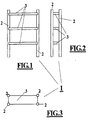
- Figures 1 to 3 show a boltless shelf, which in its entirety with the Reference numeral 1 is marked.
- a shelf field is made up of four bars 2 limited, between which one corresponds to the number of floors desired Number of shelves 3 is used.
- the shelf is by adding two additional spars, for example, expandable by a shelf field, etc.
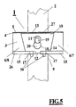
- FIGS. 4 and 5 show the rear spar 2 in the corner region 9.
- the shelf 3 consists of an angular profile, the horizontally oriented leg 4 of which forms the bearing surface 5 and the vertical leg 6 of which forms the front cheek 8 on the one hand and the side cheek 7 of the shelf 3 on the other hand, this represents a trough which is open at the bottom and which is rectangular in accordance with the shelf length and shelf depth.
- the clamping wedge 10 is inserted, which is of a trapezoidal shape.
- the clamping wedge 10 extends diagonally in the corner area 9 so that it is positioned in front of the spar 2 in front of the opening created by the notch 12.
- the clamping wedge 10 can be inserted into corresponding openings 17 of the support shoulder 15 formed horizontally at the free end of the vertical leg 6, so that a pre-fixation of the clamping wedge 10 to maintain its position is achieved here.
- the retention adapter identified by reference number 11 is then inserted into the widened region 20 of the opening 18 in the clamping wedge 10 and inserted into an equally shaped opening in the spar 2.
- the opening 18 in the clamping wedge 10 is incorporated in such a way that the widened region points downwards and the narrowed region 19 points upwards and has approximately the shape of an upside-down keyhole.
- the opening 21 shown in more detail in FIG. 8 is arranged rotated by 180 °, so that when the bearing surface 5 of the shelf 3 attached to the spar 2 of the shelf adapter 3 is pressed, the constricted areas 19 and 23 of the two openings 21 and 18 are included reaches behind its widened heads 24 (FIG. 9).
- FIG. 6 shows a front view of the clamping wedge 10. In a particularly preferred embodiment of the present invention, this consists of a trapezoidal plate, which subsequently serves as an approximately vertically orientable leg!
- An angle 27 is formed approximately at right angles to this, so that the clamping wedge 10 is formed approximately as an angular body, as shown in FIG. 7. It is also possible, instead of providing a rectangular embodiment, to bend the clamping wedge 10 slightly, so that between the angle 27 and the leg 28 an angle is formed at 90 °.
- the opening 18 can clearly be seen in FIG. 6, which has the shape of an upside-down keyhole, so that there is a narrowed area 19 and a widened area 20.
- the size of the widened area 20 is to be selected so that the head 24 (FIG. 9) of the retention adapter 11 can be passed through.
- the narrowed area 19, on the other hand, is to be made so narrow that here the shaft 25 of the retention adapter 11 (FIG.
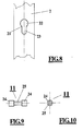
- FIG. 8 shows the spar 2. This can be provided with a multiplicity of openings 21 arranged one above the other in order to arrange any number of shelves at any desired location.
- the opening 21 has both a widened region 22 and a narrowed region 23, so that the same interaction with the retention adapter is ensured as with the opening in the clamping wedge.
- FIGS. 9 and 10 show the retention adapter 11. It essentially consists of a shaft 25 and heads 24 which are integrally formed on its two free ends.
- Both the shaft 25 and the heads 24 thereof can be of cylindrical cross section, the shaft having a smaller diameter than the heads have, so that both the implementation and the reaching behind the clamping wedge or the inner wall of the spar is ensured.
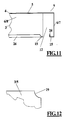
- FIG. 11 shows the shelf 3 without a clamping wedge inserted, so that the notch 12 incorporated in the corner area 9 is visible. Otherwise, the same elements are identified by the same reference numerals as in the previous drawings.
- Figure 12 shows the shelf 3 with a plan view of the support surface 5. Here it can be seen that the shelf 3 or the support surface 5 has a recess 29 corresponding to the shape of the spar, so that the shelf is pressed against the spar by the wedging can.
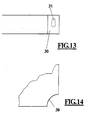
- FIG. 13 and 14 show a stabilizing web 30 arranged in the corner region 9 of the shelf 3, for example in order to avoid the tabs on the clamping wedge.
- the web 30 must have an opening 31 congruent with the opening in the clamping wedge.
- FIG. 15 shows the carrying fork 42. This is essentially H-shaped. Legs 48 and 49 projecting downwards and upwards from an approximately horizontally oriented crosspiece 47. Separate slots are formed between the two legs 48 and 49 by the crosspiece 47. The lower slot 50 is open at the bottom. which is hereinafter referred to as the receiving gap 46, is open at its upward-facing end.
- the receiving gap 46 is preferably of a trapezoidal shape and tapers in relation to the insertion opening 53 towards its bottom 54, which is the upper edge of the transverse web 47. There are therefore four arms 41, 55, 56 and 57, the receiving gap 46 remaining between the arm 41 and the outer wall 45 of the bar 2, since the arm 55 comes to lie within the bar 2.
- the receiving gap 46 therefore has approximately the width in its base area, which together corresponds to the thickness of the clamping wedge and the spar wall.
- the carrying fork 42 is inserted into the slot 21 of the bar 2 that can be seen in FIG. For this purpose, the carrying fork 42 is inclined so that the arm 55 lowers against the spar 2.
- FIG. 17 shows a front view of the clamping wedge 10.
- this consists of a square or rectangular plate.
- the slot 40 can be clearly seen in FIG. 17, which is designed to be open when the clamping wedge 10 is rotated by 180.degree.
- the clamping wedge 10 has on its underside 14 two spaced apart tabs 16 by means of which it can be inserted into the shelf.
- FIGS. 18 and 19 show the shelf 3 mounted on the spar 2.
- the support surface 5 is shown broken away. The clamping wedge 10 is inserted diagonally and vertically in the corner area 9.
- the shelf 3 has in the corner area 9 a diagonally extending notch 12, which is limited by the end edges 62 and 63 of the profile leg 6 and is of a smaller size than the diagonally extending surface of the clamping wedge 10 so that it engages behind the legs 6 and can hit it with its vertical edges 64 and 65.
- the minimum distance between the clamping wedge 10 and the spar 2 is thus limited.
- FIG. 20 shows the mounting position (without shelf) and shows how the clamping wedge 10 and the spar are clamped and clamped in the carrying fork 42, ie in the area of the bottom 54 of the receiving gap 46.
- the shelf is drawn with its corner area to the spar 2, as is the case in all the other variants shown.
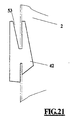
- FIG. 21 shows the possible play between the carrying fork 42 and the spar 2 after the fork has been inserted.
- FIG. 22 shows a particularly preferred embodiment of the clamping wedge 10.
- the tabs 16 are undercut with a transverse groove 52, so that they acquire a hook-like shape. This serves for self-locking of the clamping wedge 10 in the shelf 3.
- Corresponding openings 17 are provided in the support shoulders 15 of the shelf 3, through which the tabs 16 of the clamping wedge 10 can be inserted. The openings 17 are also aligned diagonally like the clamping wedge.
- FIGS. 23 and 24 show only a section, so that actually two tabs 16 arranged in mirror image fulfill this function.
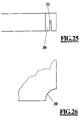
- FIGS. 25 and 26 show a stabilizing web 30 arranged in the corner region 9 of the shelf 3, for example in order to avoid the tabs on the clamping wedge.
- FIG. 27 shows a cylindrical retention adapter 11 in a further embodiment.
- a cylindrical shaft (70) which is provided with specially shaped heads at its free ends. The function of these corresponds to the retention adapter of the type already described above.
- the first head is a circular-cylindrical extension 71.
- the other head is a 72 in the shape of a cone. Between the two heads or lugs 71 and 72, the cylindrical shaft 70 is enclosed, which has a smaller diameter than both heads, so that it can be inserted and carried out through the openings of the clamping wedge and spar, which are modified accordingly.
- the groove 73 undercuts the shaft 70 and the head 72.
- FIG. 33 shows the retention adapter 11 as a flat plate.
- a narrower web 75 with an arrow-shaped head 76 connects to the grip disk 74.
- the groove 77 can be seen, which corresponds to the function of the groove 73.
- the embodiments shown in the figures are particularly preferred variants. Of course, instead of spars with circular cross-sections, angular or other cross-sectional profiles can also be used. Both metal and suitable plastics can be used as materials for the retention adapter or the clamping wedge.
Landscapes
- Cabinets, Racks, Or The Like Of Rigid Construction (AREA)
- Clamps And Clips (AREA)
Applications Claiming Priority (4)
| Application Number | Priority Date | Filing Date | Title |
|---|---|---|---|
| DE29713392U | 1997-07-25 | ||
| DE29713221U | 1997-07-25 | ||
| DE29713221U DE29713221U1 (de) | 1997-07-25 | 1997-07-25 | Steckregal |
| DE29713392U DE29713392U1 (de) | 1997-07-15 | 1997-07-25 | Steckregal |
Publications (2)
| Publication Number | Publication Date |
|---|---|
| EP0893080A2 true EP0893080A2 (fr) | 1999-01-27 |
| EP0893080A3 EP0893080A3 (fr) | 1999-03-24 |
Family
ID=26060535
Family Applications (1)
| Application Number | Title | Priority Date | Filing Date |
|---|---|---|---|
| EP98110124A Withdrawn EP0893080A3 (fr) | 1997-07-25 | 1998-06-03 | Rayonnage de stockage |
Country Status (1)
| Country | Link |
|---|---|
| EP (1) | EP0893080A3 (fr) |
Cited By (1)
| Publication number | Priority date | Publication date | Assignee | Title |
|---|---|---|---|---|
| EP1314376A1 (fr) * | 2001-11-23 | 2003-05-28 | Arnaud Duwicquet | Taquet support d'étagères |
Family Cites Families (5)
| Publication number | Priority date | Publication date | Assignee | Title |
|---|---|---|---|---|
| US2990067A (en) * | 1958-10-01 | 1961-06-27 | Harbor Metal Products Corp | Shelf structure |
| CH455191A (it) * | 1967-04-13 | 1968-04-30 | Omp Ohg Pavesi | Scaffalatura componibile |
| DE2038877A1 (de) * | 1970-08-05 | 1972-02-10 | Schaefer Gmbh Fritz | Regal |
| US4230052A (en) * | 1979-05-10 | 1980-10-28 | Cogan Wire & Metal Products (1974) Limited | Corner support for a shelving system |
| US4513669A (en) * | 1983-01-03 | 1985-04-30 | Lyon Metal Products, Incorporated | Shelving structure and clip used therein |
-
1998
- 1998-06-03 EP EP98110124A patent/EP0893080A3/fr not_active Withdrawn
Cited By (2)
| Publication number | Priority date | Publication date | Assignee | Title |
|---|---|---|---|---|
| EP1314376A1 (fr) * | 2001-11-23 | 2003-05-28 | Arnaud Duwicquet | Taquet support d'étagères |
| FR2832604A1 (fr) * | 2001-11-23 | 2003-05-30 | Franck Duwicquet | Taquet support d'etageres |
Also Published As
| Publication number | Publication date |
|---|---|
| EP0893080A3 (fr) | 1999-03-24 |
Similar Documents
| Publication | Publication Date | Title |
|---|---|---|
| DE3214727C2 (fr) | ||
| DE69529669T2 (de) | Tragelement für gitterstrukturen | |
| DE69514817T2 (de) | Tragvorrichtung für abgehängte decken | |
| DE1805523A1 (de) | Stuetzanordnung fuer Fachbretter od.dgl. | |
| EP1442942A1 (fr) | Raccord à brides entre un longeron de véhicule et un élément de support fixable à ce dernier | |
| DE1684219C3 (de) | Vorrichtung zum Verbinden von Gerüstteilen | |
| EP3440281A1 (fr) | Ferrure pour une plinthe d'un échafaudage | |
| DE20112447U1 (de) | Halterahmen zum Präsentieren von Waren, Gegenständen o.dgl. | |
| DE9013103U1 (de) | Befestigungsorgan für Heizkörper | |
| DE4109070C2 (fr) | ||
| EP4223180B1 (fr) | Système de rayonnage | |
| DE1988325U (de) | Langgestrecktes moebelteil mit steckverbindung. | |
| EP0893080A2 (fr) | Rayonnage de stockage | |
| DE69607893T2 (de) | Verbindungsvorrichtung für Leichtbau-Metallregale | |
| DE69011489T2 (de) | Verbindungselemente für Rückenlehnen mit dazugehörigen Sitzen. | |
| DE3207535C2 (de) | Gelenkarmmarkise mit Gehäuse | |
| DE29713392U1 (de) | Steckregal | |
| WO2006092156A1 (fr) | Element paroi | |
| DE4006110C2 (fr) | ||
| DE29619688U1 (de) | Regalrahmen | |
| DE29713221U1 (de) | Steckregal | |
| EP0213236A2 (fr) | Dispositif de type rayonnage | |
| DE29712455U1 (de) | Regal | |
| DE10043330A1 (de) | Wandhalter für Verkleidungstafeln, insbesondere Fassadenelemente | |
| DE6802280U (de) | Regal aus metall |
Legal Events
| Date | Code | Title | Description |
|---|---|---|---|
| PUAI | Public reference made under article 153(3) epc to a published international application that has entered the european phase |
Free format text: ORIGINAL CODE: 0009012 |
|
| AK | Designated contracting states |
Kind code of ref document: A2 Designated state(s): AT BE CH DE ES FR GB IT LI NL |
|
| AX | Request for extension of the european patent |
Free format text: AL;LT;LV;MK;RO;SI |
|
| PUAL | Search report despatched |
Free format text: ORIGINAL CODE: 0009013 |
|
| RTI1 | Title (correction) | ||
| AK | Designated contracting states |
Kind code of ref document: A3 Designated state(s): AT BE CH CY DE DK ES FI FR GB GR IE IT LI LU MC NL PT SE |
|
| AX | Request for extension of the european patent |
Free format text: AL;LT;LV;MK;RO;SI |
|
| AKX | Designation fees paid |
Free format text: AT BE CH DE ES FR GB IT LI NL |
|
| STAA | Information on the status of an ep patent application or granted ep patent |
Free format text: STATUS: THE APPLICATION IS DEEMED TO BE WITHDRAWN |
|
| 18D | Application deemed to be withdrawn |
Effective date: 19990925 |