EP0893195A2 - Wekzeugaufnahme für rundlaufende Zerspanungswerkzeuge - Google Patents
Wekzeugaufnahme für rundlaufende Zerspanungswerkzeuge Download PDFInfo
- Publication number
- EP0893195A2 EP0893195A2 EP98115795A EP98115795A EP0893195A2 EP 0893195 A2 EP0893195 A2 EP 0893195A2 EP 98115795 A EP98115795 A EP 98115795A EP 98115795 A EP98115795 A EP 98115795A EP 0893195 A2 EP0893195 A2 EP 0893195A2
- Authority
- EP
- European Patent Office
- Prior art keywords
- tool
- lubricant
- tool holder
- dispensing container
- drilling tool
- Prior art date
- Legal status (The legal status is an assumption and is not a legal conclusion. Google has not performed a legal analysis and makes no representation as to the accuracy of the status listed.)
- Granted
Links
Images
Classifications
-
- B—PERFORMING OPERATIONS; TRANSPORTING
- B23—MACHINE TOOLS; METAL-WORKING NOT OTHERWISE PROVIDED FOR
- B23B—TURNING; BORING
- B23B51/00—Tools for drilling machines
- B23B51/06—Drills with lubricating or cooling equipment
-
- B—PERFORMING OPERATIONS; TRANSPORTING
- B23—MACHINE TOOLS; METAL-WORKING NOT OTHERWISE PROVIDED FOR
- B23B—TURNING; BORING
- B23B51/00—Tools for drilling machines
- B23B51/06—Drills with lubricating or cooling equipment
- B23B51/068—Details of the lubricating or cooling channel
-
- B—PERFORMING OPERATIONS; TRANSPORTING
- B23—MACHINE TOOLS; METAL-WORKING NOT OTHERWISE PROVIDED FOR
- B23Q—DETAILS, COMPONENTS, OR ACCESSORIES FOR MACHINE TOOLS, e.g. ARRANGEMENTS FOR COPYING OR CONTROLLING; MACHINE TOOLS IN GENERAL CHARACTERISED BY THE CONSTRUCTION OF PARTICULAR DETAILS OR COMPONENTS; COMBINATIONS OR ASSOCIATIONS OF METAL-WORKING MACHINES, NOT DIRECTED TO A PARTICULAR RESULT
- B23Q11/00—Accessories fitted to machine tools for keeping tools or parts of the machine in good working condition or for cooling work; Safety devices specially combined with or arranged in, or specially adapted for use in connection with, machine tools
- B23Q11/10—Arrangements for cooling or lubricating tools or work
Definitions
- the drilling tool such as a drill, a reamer or generally a concentric tool (hereinafter referred to drill taken) heats up together with the workpiece material.
- a cooling lubrication with a Cooling lubricant hereinafter referred to as lubricant
- Wet machining is a high excess of lubricant in liquid form in the Drilled hole.
- this type of cooling lubrication is relatively high System costs and costs for lubricant disposal, cleaning etc.
- Lubrication systems are therefore used in which the lubricant with the help of conveyors over the spindle one Processing machine and at least one existing in the drill Lubricant channel the respective effective points, for example in the area of Main drill cutting or the rake face.
- Lubrication systems are relatively large Lubricant quantity required because the supply lines run from the Supply device to the processing machine, for example. lead to their spindle must be filled with lubricant.
- From DE 196 18 540 A1 is one Tool holder for coolant or lubricant-supplied tools known in of which a lubricant reservoir is integrated.
- the memory is in one Direction of delivery spring-loaded piston pressurized. Disadvantage of such In addition to the elaborate production, tool holder is above all that the lubricant in the reservoir is always essentially the same, pressure applied by the spring. An adaptation of the Pressure to different viscosities of the lubricant or a variation the amount of lubricant delivered into the effective range of the drilling tool different pressures are possible.
- the object of the invention is to propose a tool holder with which A technically simple way to lubricate small quantities with exact dosing is feasible.
- Lubricant flow can be done in general without great technical effort due to the size of the Outlet openings of the drilling tool can be controlled. Relating to one certain drilling tool speed can be relatively accurate in this way Determine the lubricant flow.
- a gas cushion of the proposed type can either in the Donor containers are available or are only generated when needed. Is to for example, the container through a separating piston into a lubricant chamber and separated into a gas generating room. Located in the gas generation room an electrolyte liquid into which a solid can be introduced if necessary, which reacts with the electrolyte liquid to produce gas.
- the dispensing container arranged in a tool holder can, depending on Need to be filled with more or less viscous lubricants.
- the fluidic connection between the dispenser and the Lubricant channel of the drilling tool with the help of a particular centrifugally operated shut-off valve is stoneable. A drilling tool can thus be replaced without lubricant from the dispenser runs out.
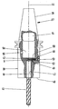
- a tool holder 37 according to the invention is shown in the illustration schematic sectional view shown. It has a conical shape Holding area 38 with which it fits into a corresponding fixing recess Machining or machine tool (not shown) can be used.
- a second area 39 adjoining the conical area 38 formed cylindrical and has one on its end face 40 Receiving bore 42 for a drill 43.
- a dispensing container 9a is arranged around the middle part of the Tool holder 38 and coaxial to the central longitudinal axis 44 of the Tool holder 38.
- the Receiving bore 42 area of the dispensing container 9a facing away is a expandable, ie pressurized gas cushion arranged.
- the Dispenser container can be filled with lubricant via a refill opening (55) bsw. refillable.
- a central lubricant channel 10 is arranged on the shaft-side end face 6 of the drill 43 opens out.
- a connecting channel 47 which extends from the dispensing container 9a to to the front side up to the end in the end face 6 of the drill 43 Lubricant channel 10 extends.
- the connecting channel 47 is one Centrifugally operated shutoff valve 48 is closed, which is designed as follows: In a slide 50 is arranged in a radially arranged receiving bore 49, which is acted upon by a compression spring 52 in the closing direction. The compression spring 52 is supported with its other end on a locking ball 53.
- the check valve 48 operates as follows: when the drill 43 rotates, the slide 50 due to centrifugal force moved radially outward against the action of the compression spring 52. As a result, it at least gives the cross-sectional area of the connecting channel 47 partially free. The lubricant under pressure in the dispensing container 9a becomes then via the connecting channel 47 into the lubricant channel 10 and finally to promoted the points of action in the area of the drill tip 7.
Landscapes
- Engineering & Computer Science (AREA)
- Mechanical Engineering (AREA)
- Auxiliary Devices For Machine Tools (AREA)
- Drilling And Boring (AREA)
- Drilling Tools (AREA)
- Earth Drilling (AREA)
- Cutting Tools, Boring Holders, And Turrets (AREA)
- Packaging Of Annular Or Rod-Shaped Articles, Wearing Apparel, Cassettes, Or The Like (AREA)
Abstract
Description
- 37
- Werkzeugaufnahme
- 38
- Haltebereich
- 39
- Bereich
- 40
- Stirnseite
- 41
- Durchmesser
- 42
- Aufnahmebohrung
- 43
- Bohrer
- 44
- Mittellängsachse
- 45
- Federraum
- 46
- Kolbenstange
- 47
- Verbindungskanal
- 48
- Sperrventil
- 49
- Aufnahmebohrung
- 50
- Schieber
- 51
- Schließkugel
- 52
- Druckfeder
- 53
- Rastkugel
- 54
- Luftpolster
- 55
- Nachfüllkanal
Claims (5)
- Werkzeugaufnahme zum Einspannen eines Bohrwerkzeugs, mit einem darin integrierten Spendebehälter (9a) für einen Schmierstoff, wobei der Spendebehälter bei eingespanntem Bohrwerkzeug (43) mit wenigstens einem internen Schmierstoffkanal (10) des Bohrwerkzeugs fluidisch verbunden und druckbeaufschlagt ist,
gekennzeichnet durch
eine Druckbeaufschlagung mit einem im Spendebehälter angeordneten expandierbaren Gaspolster. - Werkzeugaufnahme nach Anspruch 1,
dadurch gekennzeichnet,
daß das Gaspolster im Spendebehälter (9a) erzeugbar ist. - Werkzeugaufnahme nach Anspruch 1 oder 2,
gekennzeichnet durch
einen wiederbefüllbaren Spendebehälter (9). - Werkzeugaufnahme nach Anspruch 3,
gekennzeichnet durch
einen sich von der Außenseite der Werkzeugaufnahme in den Innenraum des Spendebehälters (9a) erstreckenden Nachfüllkanal (55). - Werkzeugaufnahme nach einem der Ansprüche 1 bis 4,
dadurch gekennzeichnet,
daß die fluidische Verbindung zwischen dem Spendebehälter (9) und dem Schmierstoffkanal (10) mit Hilfe eines fliehkraftbetätigten Sperrventils (48) steuerbar ist.
Applications Claiming Priority (5)
| Application Number | Priority Date | Filing Date | Title |
|---|---|---|---|
| DE29512745U | 1995-08-08 | ||
| DE29512745 | 1995-08-08 | ||
| DE29602997U | 1996-02-21 | ||
| DE29602997 | 1996-02-21 | ||
| EP96929217A EP0843609B1 (de) | 1995-08-08 | 1996-08-07 | Bohrwerkzeug, insbesondere Bohrer |
Related Parent Applications (1)
| Application Number | Title | Priority Date | Filing Date |
|---|---|---|---|
| EP96929217A Division EP0843609B1 (de) | 1995-08-08 | 1996-08-07 | Bohrwerkzeug, insbesondere Bohrer |
Publications (3)
| Publication Number | Publication Date |
|---|---|
| EP0893195A2 true EP0893195A2 (de) | 1999-01-27 |
| EP0893195A3 EP0893195A3 (de) | 1999-02-03 |
| EP0893195B1 EP0893195B1 (de) | 2002-05-02 |
Family
ID=26058116
Family Applications (2)
| Application Number | Title | Priority Date | Filing Date |
|---|---|---|---|
| EP98115795A Expired - Lifetime EP0893195B1 (de) | 1995-08-08 | 1996-08-07 | Werkzeugaufnahme für rundlaufende Zerspanungswerkzeuge |
| EP96929217A Expired - Lifetime EP0843609B1 (de) | 1995-08-08 | 1996-08-07 | Bohrwerkzeug, insbesondere Bohrer |
Family Applications After (1)
| Application Number | Title | Priority Date | Filing Date |
|---|---|---|---|
| EP96929217A Expired - Lifetime EP0843609B1 (de) | 1995-08-08 | 1996-08-07 | Bohrwerkzeug, insbesondere Bohrer |
Country Status (9)
| Country | Link |
|---|---|
| EP (2) | EP0893195B1 (de) |
| JP (2) | JPH11507880A (de) |
| CN (2) | CN1085128C (de) |
| AT (2) | ATE216938T1 (de) |
| CA (1) | CA2232333A1 (de) |
| DE (2) | DE59603239D1 (de) |
| ES (2) | ES2138829T3 (de) |
| RU (1) | RU2268110C2 (de) |
| WO (1) | WO1997005987A1 (de) |
Families Citing this family (35)
| Publication number | Priority date | Publication date | Assignee | Title |
|---|---|---|---|---|
| DE19945480B4 (de) * | 1999-09-22 | 2008-01-31 | MAPAL Fabrik für Präzisionswerkzeuge Dr. Kress KG | Werkzeug zur spanabtragenden Bearbeitung von Werkstücken |
| FR2866822B1 (fr) * | 2004-03-01 | 2007-04-06 | Rusch Outil De Prec | Outil de tournage |
| DE102006058217A1 (de) * | 2006-12-11 | 2008-06-19 | Kästner Präzisionswerkzeuge GmbH | Bohrwerkzeug, insbesondere Spiralbohrer |
| KR101107292B1 (ko) * | 2009-10-15 | 2012-01-20 | 이화다이아몬드공업 주식회사 | 천공용 공구 |
| RU2570965C2 (ru) * | 2009-10-20 | 2015-12-20 | Смит Энд Нефью, Инк. | Соединительная система |
| RU2481176C2 (ru) * | 2011-01-24 | 2013-05-10 | Константин Эдуардович Огоньков | Режущий инструмент (варианты) и способ резания |
| RU2481925C2 (ru) * | 2011-02-21 | 2013-05-20 | Константин Эдуардович Огоньков | Крепежное устройство для режущих пластин |
| RU2563396C2 (ru) * | 2011-05-30 | 2015-09-20 | Кабусики Кайся Миянага | Устройство подачи охлаждающей жидкости и электрическая буровая установка, содержащая такое устройство |
| JP5980619B2 (ja) * | 2012-08-15 | 2016-08-31 | 東芝機械株式会社 | ボーリング用工具およびボーリング用工作機械 |
| CN104174902A (zh) * | 2013-05-21 | 2014-12-03 | 苏州锑玛精密机械有限公司 | 一种高精度内冷阶梯钻 |
| DE102013210355B4 (de) | 2013-06-04 | 2022-11-17 | Kennametal Inc. | Zerspanungswerkzeug sowie Verfahren zur Herstellung eines Zerspanungswerkzeug |
| WO2015117079A1 (en) * | 2014-01-31 | 2015-08-06 | 5Me Ip, Llc | Rotary cutting tool with an internal cooling cavity |
| DE102014104192B3 (de) | 2014-03-26 | 2015-05-28 | Hochschule Furtwangen | Vorrichtung zur Aufnahme eines Werkzeugs |
| DE102014207507B4 (de) | 2014-04-17 | 2021-12-16 | Kennametal Inc. | Zerspanungswerkzeug sowie Verfahren zum Herstellen eines Zerspanungswerkzeugs |
| DE102014020086B4 (de) | 2014-04-17 | 2024-06-06 | Kennametal Inc. | Zerspanungswerkzeug sowie Verfahren zum Herstellen eines Zerspanungswerkzeugs |
| DE102014207510B4 (de) | 2014-04-17 | 2021-12-16 | Kennametal Inc. | Zerspanungswerkzeug sowie Verfahren zum Herstellen eines Zerspanungswerkzeugs |
| CN104785806A (zh) * | 2015-04-20 | 2015-07-22 | 中山市利群精密实业有限公司 | 数控机床的刀杆结构 |
| CN104786096A (zh) * | 2015-04-20 | 2015-07-22 | 中山市利群精密实业有限公司 | 数控机床的冷却装置 |
| DE202016004094U1 (de) | 2016-07-01 | 2017-04-06 | Alfred Martin Hand | Zerspanungswerkzeug |
| JP6362803B1 (ja) | 2018-01-23 | 2018-07-25 | 株式会社松浦機械製作所 | 切削工具 |
| CN108274048A (zh) * | 2018-05-01 | 2018-07-13 | 王旭东 | 一种用于包含台阶沉孔的通孔加工的内冷钻头 |
| CN108500855B (zh) * | 2018-05-09 | 2020-04-21 | 上海航天精密机械研究所 | 铣磨工具及其制作方法 |
| DE102018214189B4 (de) * | 2018-08-22 | 2025-10-02 | Gühring KG | Dehnspannfutter |
| JP7267766B2 (ja) * | 2019-02-14 | 2023-05-02 | 株式会社Subaru | 回転切削工具、回転切削ユニット及び被切削加工品を製作する方法 |
| JP7463674B2 (ja) * | 2019-08-27 | 2024-04-09 | 三菱マテリアル株式会社 | 刃先交換式クーラント孔付きエンドミルのエンドミル本体および刃先交換式クーラント孔付きエンドミル |
| CN110640845B (zh) * | 2019-10-30 | 2021-07-09 | 重庆涛扬建材有限公司 | 木托盘异形孔用打孔装置 |
| CN110682369B (zh) * | 2019-10-30 | 2021-06-18 | 重庆涛扬建材有限公司 | 一种木托盘异形孔的打孔工艺 |
| CN110860721B (zh) * | 2019-12-10 | 2021-01-26 | 深圳市鑫亚泰机械设备有限公司 | 一种具有冷却液回收和碎屑清洁功能的数控钻床 |
| CN111001840B (zh) * | 2019-12-10 | 2021-03-30 | 平湖市吉晨五金有限公司 | 一种数控钻孔装置 |
| RU198358U1 (ru) * | 2020-02-03 | 2020-07-02 | Федеральное государственное бюджетное образовательное учреждение высшего образования "Саратовский государственный технический университет имени Гагарина Ю.А." (СГТУ имени Гагарина Ю.А.) | Сверлильный инструмент |
| US12179276B2 (en) * | 2021-01-20 | 2024-12-31 | Iscar, Ltd. | Rotary cutting tool having an energy harvesting arrangement |
| CN112914675B (zh) * | 2021-04-06 | 2022-02-22 | 南京林业大学 | 一种皮质骨加工用医用热管钻头及其使用方法 |
| CN116352130B (zh) * | 2023-01-31 | 2023-10-31 | 淮北探宇冶金设备有限公司 | 一种高炉冷却壁冷却口钻孔装置 |
| CN117283350B (zh) * | 2023-11-10 | 2024-11-05 | 宁波轩驰轴承有限公司 | 一种轴承座加工铣削装置及其使用方法 |
| JP7636053B1 (ja) * | 2024-08-29 | 2025-02-26 | 株式会社近藤鉄工所 | 切り屑除去方法、および、切り屑除去システム |
Family Cites Families (7)
| Publication number | Priority date | Publication date | Assignee | Title |
|---|---|---|---|---|
| DE29794C (de) * | A. SÖDERSTRÖM in Stockholm | Neuerungen an Bohrhaltern und Bohrern. (Abhängig vom Patente Nr. 29046.) | ||
| DE133433C (de) * | ||||
| FR543024A (fr) * | 1921-11-04 | 1922-08-25 | Dispositif lubrificateur pour forets à trous longitudinaux d'arrosage | |
| US2847880A (en) * | 1953-06-29 | 1958-08-19 | Claude E Neidig | Cutting tool lubricators and cleaners |
| JPS58102613A (ja) * | 1981-12-04 | 1983-06-18 | Inax Corp | 貯液体孔あけ器具 |
| RO102494B1 (en) * | 1989-06-23 | 1992-02-01 | Tool with autonomous cooling system | |
| DE4327232C1 (de) * | 1993-08-13 | 1995-01-26 | Vaw Ver Aluminium Werke Ag | Vorrichtung zum Fließbohren |
-
1996
- 1996-08-07 WO PCT/EP1996/003489 patent/WO1997005987A1/de not_active Ceased
- 1996-08-07 JP JP9508129A patent/JPH11507880A/ja active Pending
- 1996-08-07 DE DE59603239T patent/DE59603239D1/de not_active Expired - Lifetime
- 1996-08-07 EP EP98115795A patent/EP0893195B1/de not_active Expired - Lifetime
- 1996-08-07 ES ES96929217T patent/ES2138829T3/es not_active Expired - Lifetime
- 1996-08-07 ES ES98115795T patent/ES2174361T3/es not_active Expired - Lifetime
- 1996-08-07 EP EP96929217A patent/EP0843609B1/de not_active Expired - Lifetime
- 1996-08-07 AT AT98115795T patent/ATE216938T1/de not_active IP Right Cessation
- 1996-08-07 CN CN96196184A patent/CN1085128C/zh not_active Expired - Fee Related
- 1996-08-07 AT AT96929217T patent/ATE185100T1/de not_active IP Right Cessation
- 1996-08-07 RU RU98103981/63A patent/RU2268110C2/ru not_active IP Right Cessation
- 1996-08-07 DE DE59609169T patent/DE59609169D1/de not_active Expired - Lifetime
- 1996-08-07 CA CA002232333A patent/CA2232333A1/en not_active Abandoned
-
1998
- 1998-09-21 CN CN98119523A patent/CN1081508C/zh not_active Expired - Fee Related
- 1998-10-21 JP JP29976598A patent/JP3260707B2/ja not_active Expired - Fee Related
Also Published As
| Publication number | Publication date |
|---|---|
| DE59609169D1 (de) | 2002-06-06 |
| CN1081508C (zh) | 2002-03-27 |
| ES2174361T3 (es) | 2002-11-01 |
| CN1212196A (zh) | 1999-03-31 |
| JPH11226843A (ja) | 1999-08-24 |
| ATE216938T1 (de) | 2002-05-15 |
| EP0843609A1 (de) | 1998-05-27 |
| EP0893195A3 (de) | 1999-02-03 |
| CN1085128C (zh) | 2002-05-22 |
| JPH11507880A (ja) | 1999-07-13 |
| RU2268110C2 (ru) | 2006-01-20 |
| WO1997005987A1 (de) | 1997-02-20 |
| CA2232333A1 (en) | 1997-02-20 |
| ES2138829T3 (es) | 2000-01-16 |
| JP3260707B2 (ja) | 2002-02-25 |
| DE59603239D1 (de) | 1999-11-04 |
| EP0843609B1 (de) | 1999-09-29 |
| ATE185100T1 (de) | 1999-10-15 |
| EP0893195B1 (de) | 2002-05-02 |
| CN1192709A (zh) | 1998-09-09 |
Similar Documents
| Publication | Publication Date | Title |
|---|---|---|
| EP0893195B1 (de) | Werkzeugaufnahme für rundlaufende Zerspanungswerkzeuge | |
| DE19538762C1 (de) | Verfahren zur Kühlung und Schmierung eines spanend arbeitenden, rotierenden Werkzeuges mit geometrisch definierter Schneide und/oder des Werkstückes im Bearbeitungsbereich u. Bearbeitungsspindel zur Durchführung des Verfahrens | |
| DE19632472C2 (de) | Kühl-/Schmiervorrichtung für eine Werkzeugmaschine | |
| EP0835173B1 (de) | Werkzeugaufnahme für kühl- bzw. schmiermittelversorgte werkzeuge und zugeordneter kühl- bzw. schmiermittelspeicher | |
| EP3023179B1 (de) | Stechklinge und Ein- und Abstechwerkzeug | |
| DE3822506C1 (de) | ||
| EP0353427B1 (de) | Walzeinheit | |
| DE10132857A1 (de) | Steuereinrichtung für die Zufuhr eines Schmiermittels und Verfahren zum Bestimmen der Schmiermittelmenge | |
| DE102021131072B3 (de) | Komponenten einer Werkzeugmaschine zur (automatisierten) Spannzangenwartung und -reinigung | |
| DE19618540A1 (de) | Werkzeugaufnahme für kühl- bzw. schmiermittelversorgte Werkzeuge und zugeordneter Kühl- bzw. Schmiermittelspeicher | |
| EP1514637B1 (de) | Vorrichtung zur Zufuhr von Schmiermitteln für Zerspanwerkzeuge | |
| DE60315854T2 (de) | Werkzeug mit gezielt vorgespanntem glied und verfahren zur herstellung eines nicht achsensymmetrischen merkmals | |
| DE19735420A1 (de) | Spangebende Bearbeitungseinrichtung mit einem Werkzeughalter | |
| DE2538786A1 (de) | Selbsttaetiger spender von gleit- schmier- und kuehlmittel, insbesondere fuer die spanabhebende metallbearbeitung | |
| DE10235996B4 (de) | Schmierstoffabgabevorrichtung | |
| DE10129501B4 (de) | Vorrichtung zur Kühlung und Schmierung eines spanend arbeitenden, rotierenden Werkzeuges | |
| DE4327232C1 (de) | Vorrichtung zum Fließbohren | |
| EP1925395B1 (de) | Verfahren zur Schmierung von gesteuert verfahrbaren Werkzeugen sowie Schmiermittelspender | |
| DE102013006111B4 (de) | Werkzeugaufnahme für ein Rotationswerkzeug | |
| DE10210630B4 (de) | Punktier-Prägekopf | |
| EP0404793A1 (de) | Verfahren zur innenzufuhr von kühl-, schmier- oder schneidmittel zu den schneidkanten oder führungsleisten eines sich drehenden bearbeitungswerkzeuges. | |
| WO2005011910A1 (de) | Drehdurchführung für minimalmengenschmierung | |
| EP2323806B1 (de) | Einwechselaggregat mit minimalmengenschmierung, vorrichtung und verfahren | |
| RU2174896C2 (ru) | Устройство для закрепления вращающихся режущих инструментов | |
| DE19820148A1 (de) | Zerspanungswerkzeug |
Legal Events
| Date | Code | Title | Description |
|---|---|---|---|
| PUAI | Public reference made under article 153(3) epc to a published international application that has entered the european phase |
Free format text: ORIGINAL CODE: 0009012 |
|
| PUAL | Search report despatched |
Free format text: ORIGINAL CODE: 0009013 |
|
| AC | Divisional application: reference to earlier application |
Ref document number: 843609 Country of ref document: EP |
|
| AK | Designated contracting states |
Kind code of ref document: A2 Designated state(s): AT BE CH DE ES FR GB IT LI LU NL SE |
|
| AK | Designated contracting states |
Kind code of ref document: A3 Designated state(s): AT BE CH DE ES FR GB IT LI LU NL SE |
|
| 17P | Request for examination filed |
Effective date: 19990303 |
|
| RAP1 | Party data changed (applicant data changed or rights of an application transferred) |
Owner name: KENNAMETAL INC. |
|
| GRAG | Despatch of communication of intention to grant |
Free format text: ORIGINAL CODE: EPIDOS AGRA |
|
| 17Q | First examination report despatched |
Effective date: 20011018 |
|
| REG | Reference to a national code |
Ref country code: GB Ref legal event code: IF02 |
|
| GRAG | Despatch of communication of intention to grant |
Free format text: ORIGINAL CODE: EPIDOS AGRA |
|
| GRAH | Despatch of communication of intention to grant a patent |
Free format text: ORIGINAL CODE: EPIDOS IGRA |
|
| GRAH | Despatch of communication of intention to grant a patent |
Free format text: ORIGINAL CODE: EPIDOS IGRA |
|
| GRAA | (expected) grant |
Free format text: ORIGINAL CODE: 0009210 |
|
| AC | Divisional application: reference to earlier application |
Ref document number: 843609 Country of ref document: EP |
|
| AK | Designated contracting states |
Kind code of ref document: B1 Designated state(s): AT BE CH DE ES FR GB IT LI LU NL SE |
|
| REF | Corresponds to: |
Ref document number: 216938 Country of ref document: AT Date of ref document: 20020515 Kind code of ref document: T |
|
| REG | Reference to a national code |
Ref country code: GB Ref legal event code: FG4D Free format text: NOT ENGLISH |
|
| REG | Reference to a national code |
Ref country code: CH Ref legal event code: EP |
|
| REF | Corresponds to: |
Ref document number: 59609169 Country of ref document: DE Date of ref document: 20020606 |
|
| REG | Reference to a national code |
Ref country code: CH Ref legal event code: NV Representative=s name: E. BLUM & CO. PATENTANWAELTE |
|
| GBT | Gb: translation of ep patent filed (gb section 77(6)(a)/1977) |
Effective date: 20020720 |
|
| PGFP | Annual fee paid to national office [announced via postgrant information from national office to epo] |
Ref country code: BE Payment date: 20020822 Year of fee payment: 7 Ref country code: AT Payment date: 20020822 Year of fee payment: 7 |
|
| PGFP | Annual fee paid to national office [announced via postgrant information from national office to epo] |
Ref country code: LU Payment date: 20020823 Year of fee payment: 7 Ref country code: CH Payment date: 20020823 Year of fee payment: 7 |
|
| ET | Fr: translation filed | ||
| REG | Reference to a national code |
Ref country code: ES Ref legal event code: FG2A Ref document number: 2174361 Country of ref document: ES Kind code of ref document: T3 |
|
| PLBE | No opposition filed within time limit |
Free format text: ORIGINAL CODE: 0009261 |
|
| STAA | Information on the status of an ep patent application or granted ep patent |
Free format text: STATUS: NO OPPOSITION FILED WITHIN TIME LIMIT |
|
| 26N | No opposition filed |
Effective date: 20030204 |
|
| PGFP | Annual fee paid to national office [announced via postgrant information from national office to epo] |
Ref country code: NL Payment date: 20030728 Year of fee payment: 8 |
|
| PG25 | Lapsed in a contracting state [announced via postgrant information from national office to epo] |
Ref country code: LU Free format text: LAPSE BECAUSE OF NON-PAYMENT OF DUE FEES Effective date: 20030807 Ref country code: AT Free format text: LAPSE BECAUSE OF NON-PAYMENT OF DUE FEES Effective date: 20030807 |
|
| PGFP | Annual fee paid to national office [announced via postgrant information from national office to epo] |
Ref country code: ES Payment date: 20030808 Year of fee payment: 8 |
|
| PG25 | Lapsed in a contracting state [announced via postgrant information from national office to epo] |
Ref country code: LI Free format text: LAPSE BECAUSE OF NON-PAYMENT OF DUE FEES Effective date: 20030831 Ref country code: CH Free format text: LAPSE BECAUSE OF NON-PAYMENT OF DUE FEES Effective date: 20030831 Ref country code: BE Free format text: LAPSE BECAUSE OF NON-PAYMENT OF DUE FEES Effective date: 20030831 |
|
| BERE | Be: lapsed |
Owner name: *KENNAMETAL INC. Effective date: 20030831 |
|
| REG | Reference to a national code |
Ref country code: CH Ref legal event code: PL |
|
| PGFP | Annual fee paid to national office [announced via postgrant information from national office to epo] |
Ref country code: GB Payment date: 20040730 Year of fee payment: 9 |
|
| PG25 | Lapsed in a contracting state [announced via postgrant information from national office to epo] |
Ref country code: ES Free format text: LAPSE BECAUSE OF NON-PAYMENT OF DUE FEES Effective date: 20040809 |
|
| PGFP | Annual fee paid to national office [announced via postgrant information from national office to epo] |
Ref country code: SE Payment date: 20040809 Year of fee payment: 9 Ref country code: FR Payment date: 20040809 Year of fee payment: 9 |
|
| PG25 | Lapsed in a contracting state [announced via postgrant information from national office to epo] |
Ref country code: NL Free format text: LAPSE BECAUSE OF NON-PAYMENT OF DUE FEES Effective date: 20050301 |
|
| NLV4 | Nl: lapsed or anulled due to non-payment of the annual fee |
Effective date: 20050301 |
|
| PG25 | Lapsed in a contracting state [announced via postgrant information from national office to epo] |
Ref country code: IT Free format text: LAPSE BECAUSE OF NON-PAYMENT OF DUE FEES;WARNING: LAPSES OF ITALIAN PATENTS WITH EFFECTIVE DATE BEFORE 2007 MAY HAVE OCCURRED AT ANY TIME BEFORE 2007. THE CORRECT EFFECTIVE DATE MAY BE DIFFERENT FROM THE ONE RECORDED. Effective date: 20050807 Ref country code: GB Free format text: LAPSE BECAUSE OF NON-PAYMENT OF DUE FEES Effective date: 20050807 |
|
| PG25 | Lapsed in a contracting state [announced via postgrant information from national office to epo] |
Ref country code: SE Free format text: LAPSE BECAUSE OF NON-PAYMENT OF DUE FEES Effective date: 20050808 |
|
| REG | Reference to a national code |
Ref country code: ES Ref legal event code: FD2A Effective date: 20040809 |
|
| EUG | Se: european patent has lapsed | ||
| GBPC | Gb: european patent ceased through non-payment of renewal fee |
Effective date: 20050807 |
|
| PG25 | Lapsed in a contracting state [announced via postgrant information from national office to epo] |
Ref country code: FR Free format text: LAPSE BECAUSE OF NON-PAYMENT OF DUE FEES Effective date: 20060428 |
|
| REG | Reference to a national code |
Ref country code: FR Ref legal event code: ST Effective date: 20060428 |
|
| PGFP | Annual fee paid to national office [announced via postgrant information from national office to epo] |
Ref country code: DE Payment date: 20150827 Year of fee payment: 20 |
|
| REG | Reference to a national code |
Ref country code: DE Ref legal event code: R071 Ref document number: 59609169 Country of ref document: DE |