EP0893216A2 - Procédé d'alimentation et goulotte d'alimentation pour une ecorceuse a disque - Google Patents
Procédé d'alimentation et goulotte d'alimentation pour une ecorceuse a disque Download PDFInfo
- Publication number
- EP0893216A2 EP0893216A2 EP98660071A EP98660071A EP0893216A2 EP 0893216 A2 EP0893216 A2 EP 0893216A2 EP 98660071 A EP98660071 A EP 98660071A EP 98660071 A EP98660071 A EP 98660071A EP 0893216 A2 EP0893216 A2 EP 0893216A2
- Authority
- EP
- European Patent Office
- Prior art keywords
- chute
- logs
- feeding
- disc
- blade
- Prior art date
- Legal status (The legal status is an assumption and is not a legal conclusion. Google has not performed a legal analysis and makes no representation as to the accuracy of the status listed.)
- Granted
Links
Images






Classifications
-
- B—PERFORMING OPERATIONS; TRANSPORTING
- B27—WORKING OR PRESERVING WOOD OR SIMILAR MATERIAL; NAILING OR STAPLING MACHINES IN GENERAL
- B27L—REMOVING BARK OR VESTIGES OF BRANCHES; SPLITTING WOOD; MANUFACTURE OF VENEER, WOODEN STICKS, WOOD SHAVINGS, WOOD FIBRES OR WOOD POWDER
- B27L11/00—Manufacture of wood shavings, chips, powder, or the like; Tools therefor
- B27L11/002—Transporting devices for wood or chips
Definitions
- the present invention concerns a feeding method and a feeding chute of a disc chipper fed by means of the gravity.
- a disc chipper is generally used for chipping wood prior to further processing.
- the logs are fed along an inclined chute against the blade disc of the chipper.
- the blade disc rotates around a horizontal or less than 20° inclined axle.
- the logs slide against the blade disc due to the gravity. Knives are attached to the blade disc in about the direction of the radius, chipping the wood against a stationary counter blade.
- the logs encounter the blade disc at a feeding angle which in a chute fed chipper is the angle between the plane of the disc and the plane including the log and perpendicular to the plane of the disc.
- Test have shown that the quality of chips improves when the feeding angle between the log and the blade disc is decreased.
- the decreasing of the feeding angle is, however, restricted by the increase of the size of the shearing ellipse of the head of the log, which results in the decrease of the cross section the feeding funnel, if the feeding opening cannot be enlarged at the same time.
- practice has proven that smaller feeding angles increase feeding problems of the chipper, as the shearing surface of the log increases and the balancing effect of the gravity on the feed decreases.
- FIG. 1 shows a disc chipper presently used for the chipping of wood.
- the chipper comprises a blade disc 1, a shaft 2, a feeding chute 3, a housing 4 and bearings 5.
- the drive of the chipper consists of a coupling 6 and a motor 7.
- the logs 10 to be chipped are fed into the chipper so that the angle between the fed log 10 and the blade disc is a.
- the angle in question is traditionally 38°, and the logs rest relatively stable against the bottom 8 of the feeding funnel.
- the angle a is only 32°, and thus, the surface pressure of the logs against the bottom of the feeding chute is significantly smaller, while the shearing area of the head of the log is significantly larger. This results in that the logs easily turn during the chipping, so that the quality advantage achieved by the change of the feeding angle is reduced.
- FIG. 2 shows a conventional blade arrangement of a chipper. Wear plates 11 are attached by means of bolts 9 to the blade disc 1. The knives 12 of the chipper are kept in their position by means of a knife base 13 and knife bolts 14.
- the support construction 17 of the bottom 8 of the feeding chute forms a support base for a counter blade 15, the upper surface thereof having the shape of the bottom of the chute 8 and forming an extension to the chute, receiving the chipping forces and, being subject to strong wearing, easily changeable because it is fixed by bolts 16 to the base 17.
- the logs 10 are fed against the wear plate 11, and the knives 12 cut off chips 18 which are discharged along an opening 19 in the blade disc 1. Good quality of chips requires that the logs 10 encounter the blade disc in a correct position so that the angle a remains stable and no lateral angles occur.
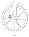
- Figure 3 shows a plane of the blade disc 1 with knives 12.
- the housing of the feeding chute 3 is shown with a dashed line 20, and the surface plane of the counter blade forming the lower end of the chute is shown with a line 21.
- the shearing area of the log is shown by an ellipse 22.
- the chipping force FH forms supporting forces F K1 and F K2 on the surface of the counter blade.
- the surface shape of the counter blade in accordance with figure 3 provides a stable feeding to the log 10 by means the two supporting forces FK, but a disadvantage is the fact that F K1 + F K2 > F H .
- the chipper of figure 3 has a "radial knife” which "chops" off the chips and there is no cutting movement in the direction of the cutting edge of the knife.
- chippers are provided with knives 12 that are placed ahead of or after the radius.
- One chipper of this kind is e.g. the traditional Carthage chipper of the 50's, constructed in accordance with figure 4, with a knife 12 arranged after the radius.
- the knives are placed behind to the extent of an auxiliary circle R.
- the radius R forms a circle, on the tangent of which the points of the knives are arranged.
- the radius R defines the cutting speed in the direction of the cutting edge of the knife.
- the feeding chute of figure 8 is provided with knives arranged ahead of the radius, and the cutting force acting on the direction of the cutting edge of the knife pulls the logs towards the shaft so that FH acts on the corner between the counter blade and the inner side of the feeding chute, so that F K1 and F K2 form a strong friction force creating problems to the feeding of the wood.
- the chute of figure 8 operates well with big logs and with a relatively small production.
- chippers that can chip a great number of logs at the same time. Therefore chippers e.g. shown in figure 5 have been constructed, having a large feeding opening and almost a horizontal chipping surface 21 of the counter blade. This levelled bottom construction does not provide guiding of the logs by the gravity, and the radial knives do not give cutting forces in the direction of the cutting edge of the knife. The logs are only guided by the "scissors forces" which are dependent on the diameter of the log. This has the result that the "scissors force” tends to move big logs from the inner circle to the outer periphery and vice versa.
- the feeding method and the construction of the feeding chute in accordance with the invention is based on the analyzing of the operation problems of the mass production chippers and on the utilization of the phenomena disturbing the chipping.
- a significant feature of the invention is the fact that the feeding of the wood in a traditional well functioning chipper is implemented in a plurality of chipping positions so that a good and stable guiding of the log is achieved also with a large feeding chute. This is achieved by shaping the bottom of the feeding chute and the counter blade in such a way that the chipping force is directed so that the friction force against the bottom of the feeding chute and the counter blade of the lower part thereof is increased only a little by dividing the chipping force into a great main supporting force and a considerably smaller guiding side support force.
- a feeding chute in accordance with the invention is shown in figure 6, where logs 10 and 10' are guided into the right chipping direction in different chipping positions which are arranged side by side on the upper surface of the counter blade.
- the surface 21' of the counter blade facing next to the shaft forms an angle ⁇ ' with the horizontal centre line 25 of the surface of the blade disc of the chipper.
- the outer surface 21" of the counter blade forms a bigger angle ⁇ " with respect to the centre line 25 of the blade disc of the chipper.
- the deviation angle ⁇ ' and ⁇ " of the chipping force F H from perpendicular to the counter blade defines the magnitude of the laterally guiding support force.
- Figure 6a shows a counter blade of the chipper with three adjacent chipping positions for logs 10, 10' and 10".
- the support surface ofthe counter blade is formed by three successive portions 21', 21" and 21' ", which have the angles ⁇ ', ⁇ " and ⁇ ' " with respect to the horizontal centre line 25 of the blade disc.
- the size order of said angles is such that ⁇ ' ⁇ ⁇ " ⁇ ⁇ ' ", and they are chosen according to the diameter distribution of the logs and the desired "scissors force" effect.
- a step in other words a short side wall portion 24 or 24', the height thereof being chosen in accordance with the diameter of the log.
- a suitable height for example for the log 10' of ⁇ 200 mm is 25 mm.
- a suitable angle e.g. between the surface of the step 24 and the surface of the counter blade 21" is about 120 - 160°, so that the surface 24 forms a firm shoulder.
- the bottom 8 of the feeding chute has the shapes corresponding to the counter blade 15, and two feeding grooves 31, 32 are formed therein, as shown in figure 9a.
- the feeding of the logs fed into the chipper takes place so that the most of the logs slide by the effect of the gravity towards the blade disc at the position shown by the log 10.
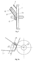
- the head of the log 10 encounters the blade disc 1 as shown in figure 7, and when the chipping begins, a small shearing surface 26 is formed, and the shearing force F H in accordance with figure 7a acts towards the counter blade 21 so that the angle ⁇ between the force FH and the counter blade 21 is significantly less than 90°, and the log 10 slides outwards from the centre 29 of the blade disc in the direction of an arrow S 1 , due to the "scissors force".
- the guiding function of the feeding chute and the counter blade is significantly improved, especially with short logs and with the tails of long logs.
- the method in accordance with the invention is of significant advantage when the production capacity of the chipper is more than 100 m 3 /hour with small logs and more than 200 m 3 /hour with big logs.
Landscapes
- Engineering & Computer Science (AREA)
- Life Sciences & Earth Sciences (AREA)
- Manufacturing & Machinery (AREA)
- Mechanical Engineering (AREA)
- Wood Science & Technology (AREA)
- Forests & Forestry (AREA)
- Debarking, Splitting, And Disintegration Of Timber (AREA)
- Feeding And Watering For Cattle Raising And Animal Husbandry (AREA)
- Mixers Of The Rotary Stirring Type (AREA)
- Measuring Pulse, Heart Rate, Blood Pressure Or Blood Flow (AREA)
- Diaphragms For Electromechanical Transducers (AREA)
- Feeding Of Articles To Conveyors (AREA)
- Crushing And Pulverization Processes (AREA)
Applications Claiming Priority (2)
| Application Number | Priority Date | Filing Date | Title |
|---|---|---|---|
| FI973078A FI102820B (fi) | 1997-07-22 | 1997-07-22 | Menetelmä ja syöttösuiste puiden syöttämiseksi kiekkohakkuun |
| FI973078 | 1997-07-22 |
Publications (3)
| Publication Number | Publication Date |
|---|---|
| EP0893216A2 true EP0893216A2 (fr) | 1999-01-27 |
| EP0893216A3 EP0893216A3 (fr) | 2000-04-12 |
| EP0893216B1 EP0893216B1 (fr) | 2003-01-29 |
Family
ID=8549285
Family Applications (1)
| Application Number | Title | Priority Date | Filing Date |
|---|---|---|---|
| EP98660071A Expired - Lifetime EP0893216B1 (fr) | 1997-07-22 | 1998-07-20 | Procédé d'alimentation et goulotte d'alimentation pour une ecorceuse a disque |
Country Status (8)
| Country | Link |
|---|---|
| US (1) | US5975169A (fr) |
| EP (1) | EP0893216B1 (fr) |
| AT (1) | ATE231776T1 (fr) |
| BR (1) | BR9802545A (fr) |
| CA (1) | CA2243380A1 (fr) |
| DE (1) | DE69811006T2 (fr) |
| ES (1) | ES2189119T3 (fr) |
| FI (1) | FI102820B (fr) |
Cited By (2)
| Publication number | Priority date | Publication date | Assignee | Title |
|---|---|---|---|---|
| FR2794678A1 (fr) * | 1999-06-09 | 2000-12-15 | Armay Borey | Machine pour le broyage de bois en copeaux |
| WO2002074508A1 (fr) * | 2001-03-16 | 2002-09-26 | Metso Paper, Inc. | Procede de reglage de la position d'alimentation dans une dechiqueteuse a disque en fonction de la taille des rondins tailles et dechiqueteuse a disque adaptee pour mettre en oeuvre le procede |
Families Citing this family (5)
| Publication number | Priority date | Publication date | Assignee | Title |
|---|---|---|---|---|
| FI104157B1 (fi) * | 1998-05-08 | 1999-11-30 | Sunds Defibrator Woodhandling | Menetelmä puun hakettamiseksi ja kiekkohakkuri |
| US7472854B1 (en) * | 2005-07-11 | 2009-01-06 | Bb&F Enterprises, Llc | Brush chipper having improved mechanical coupling arrangement for feed motor |
| US7669621B2 (en) * | 2006-08-14 | 2010-03-02 | Cem Machine, Inc. | Stationary bedknife for disc chipper apparatus |
| DE102008044866B4 (de) | 2008-08-28 | 2010-04-29 | Procon Gmbh Maschinen- U. Industrieanlagen | Mobile Holzverarbeitungsanlage |
| US8051887B2 (en) * | 2009-11-04 | 2011-11-08 | Cem Machine, Inc. | Primary and counter knife assembly for use in wood chipper |
Family Cites Families (6)
| Publication number | Priority date | Publication date | Assignee | Title |
|---|---|---|---|---|
| US3392763A (en) * | 1967-05-15 | 1968-07-16 | Ledergerber Karl | Wood chipper construction |
| FI88371C (fi) * | 1991-11-11 | 2000-05-03 | Sunds Defibrator Rauma Woodhandling Oy | Menetelmä pitkänomaisten puukappaleiden syöttämiseksi kiekkohakkuun ja kiekkohakku |
| US5139063A (en) * | 1991-12-06 | 1992-08-18 | Carthage Machine Company | Chipper sliver trimmer |
| US5261469A (en) * | 1992-11-13 | 1993-11-16 | Severson Harvey M | Apparatus for forming curled wood shavings |
| FI933131A0 (fi) * | 1993-07-08 | 1993-07-08 | Sunds Defibrator Woodhandling | Skaersystem, skaer, styrdel och fyllningsdel foer maskin anvaend i flishuggning samt foerfarande foer bytning av skaer |
| US5417263A (en) * | 1993-08-11 | 1995-05-23 | Jorgensen; Ray B. | Log chipper for lowering peak power requirements and raising chip quality |
-
1997
- 1997-07-22 FI FI973078A patent/FI102820B/fi not_active IP Right Cessation
-
1998
- 1998-07-20 AT AT98660071T patent/ATE231776T1/de active
- 1998-07-20 ES ES98660071T patent/ES2189119T3/es not_active Expired - Lifetime
- 1998-07-20 EP EP98660071A patent/EP0893216B1/fr not_active Expired - Lifetime
- 1998-07-20 DE DE69811006T patent/DE69811006T2/de not_active Expired - Fee Related
- 1998-07-20 CA CA002243380A patent/CA2243380A1/fr not_active Abandoned
- 1998-07-21 US US09/119,229 patent/US5975169A/en not_active Expired - Lifetime
- 1998-07-22 BR BR9802545-7A patent/BR9802545A/pt not_active IP Right Cessation
Cited By (2)
| Publication number | Priority date | Publication date | Assignee | Title |
|---|---|---|---|---|
| FR2794678A1 (fr) * | 1999-06-09 | 2000-12-15 | Armay Borey | Machine pour le broyage de bois en copeaux |
| WO2002074508A1 (fr) * | 2001-03-16 | 2002-09-26 | Metso Paper, Inc. | Procede de reglage de la position d'alimentation dans une dechiqueteuse a disque en fonction de la taille des rondins tailles et dechiqueteuse a disque adaptee pour mettre en oeuvre le procede |
Also Published As
| Publication number | Publication date |
|---|---|
| US5975169A (en) | 1999-11-02 |
| ES2189119T3 (es) | 2003-07-01 |
| FI973078A0 (fi) | 1997-07-22 |
| CA2243380A1 (fr) | 1999-01-22 |
| EP0893216B1 (fr) | 2003-01-29 |
| ATE231776T1 (de) | 2003-02-15 |
| DE69811006D1 (de) | 2003-03-06 |
| FI102820B1 (fi) | 1999-02-26 |
| EP0893216A3 (fr) | 2000-04-12 |
| BR9802545A (pt) | 1999-10-13 |
| DE69811006T2 (de) | 2003-11-27 |
| FI102820B (fi) | 1999-02-26 |
Similar Documents
| Publication | Publication Date | Title |
|---|---|---|
| US3069101A (en) | Wood chipper | |
| US2710635A (en) | Wood chipper | |
| US8051887B2 (en) | Primary and counter knife assembly for use in wood chipper | |
| EP0911127A2 (fr) | Couteau avec des nervures déflecteurs espacés pour déchiqueteur | |
| EP0893216B1 (fr) | Procédé d'alimentation et goulotte d'alimentation pour une ecorceuse a disque | |
| US4796818A (en) | Chip slicer improvement | |
| US4155384A (en) | Disk type wood chipper | |
| CA2331731C (fr) | Procede permettant de mettre en copeaux le bois et dechiqueteuse a disque | |
| EP1409215B1 (fr) | Couteau | |
| US5857508A (en) | Method of fastening a wear plate and a knife base to a disc chipper, and a disc chipper | |
| US4184526A (en) | Disc-shaped chipper with detachable cutting members | |
| US5937923A (en) | Chip slicer | |
| US7708039B2 (en) | Chipping apparatus having an adjustable cutting angle | |
| US20040060616A1 (en) | Method for setting the feed position in a disc chipper based on the size of logs being chipped and disc chipper suited for implementing the method | |
| CA2520887C (fr) | Couteau fixe de dechiqueteuse | |
| EP1513659B1 (fr) | Lame de dechiqueteuse | |
| US5236024A (en) | Counter blade for a disc chipper | |
| CA1280953C (fr) | Dispositif avance-grumes | |
| EP3233402B1 (fr) | Procédé de désintégration de matériau lignocellulosique dans une déchiqueteuse à tambour | |
| US6260592B1 (en) | Cutting piece and cutting arm for a debarking machine of a hollow-rotor type | |
| EP2873502A1 (fr) | Déchiqueteuse à disque avec un couteau réglable | |
| US3047244A (en) | Feed spouts for wood chippers | |
| US4706721A (en) | Double-drum wood chipper apparatus | |
| EP0177504A1 (fr) | Machine a fabriquer des copeaux |
Legal Events
| Date | Code | Title | Description |
|---|---|---|---|
| PUAI | Public reference made under article 153(3) epc to a published international application that has entered the european phase |
Free format text: ORIGINAL CODE: 0009012 |
|
| AK | Designated contracting states |
Kind code of ref document: A2 Designated state(s): AT DE ES FR GB SE |
|
| AX | Request for extension of the european patent |
Free format text: AL;LT;LV;MK;RO;SI |
|
| PUAL | Search report despatched |
Free format text: ORIGINAL CODE: 0009013 |
|
| AK | Designated contracting states |
Kind code of ref document: A3 Designated state(s): AT BE CH CY DE DK ES FI FR GB GR IE IT LI LU MC NL PT SE |
|
| AX | Request for extension of the european patent |
Free format text: AL;LT;LV;MK;RO;SI |
|
| 17P | Request for examination filed |
Effective date: 20001005 |
|
| AKX | Designation fees paid |
Free format text: AT BE CH CY DE DK LI |
|
| RBV | Designated contracting states (corrected) |
Designated state(s): AT DE ES FR GB SE |
|
| GRAH | Despatch of communication of intention to grant a patent |
Free format text: ORIGINAL CODE: EPIDOS IGRA |
|
| RAP1 | Party data changed (applicant data changed or rights of an application transferred) |
Owner name: METSO WOODHANDLING OY |
|
| GRAH | Despatch of communication of intention to grant a patent |
Free format text: ORIGINAL CODE: EPIDOS IGRA |
|
| GRAA | (expected) grant |
Free format text: ORIGINAL CODE: 0009210 |
|
| AK | Designated contracting states |
Designated state(s): AT DE ES FR GB SE |
|
| REG | Reference to a national code |
Ref country code: GB Ref legal event code: FG4D |
|
| REF | Corresponds to: |
Ref document number: 69811006 Country of ref document: DE Date of ref document: 20030306 Kind code of ref document: P |
|
| RAP2 | Party data changed (patent owner data changed or rights of a patent transferred) |
Owner name: METSO PAPER PORI OY |
|
| REG | Reference to a national code |
Ref country code: SE Ref legal event code: TRGR |
|
| REG | Reference to a national code |
Ref country code: ES Ref legal event code: FG2A Ref document number: 2189119 Country of ref document: ES Kind code of ref document: T3 |
|
| ET | Fr: translation filed | ||
| REG | Reference to a national code |
Ref country code: FR Ref legal event code: TP |
|
| PLBE | No opposition filed within time limit |
Free format text: ORIGINAL CODE: 0009261 |
|
| STAA | Information on the status of an ep patent application or granted ep patent |
Free format text: STATUS: NO OPPOSITION FILED WITHIN TIME LIMIT |
|
| 26N | No opposition filed |
Effective date: 20031030 |
|
| PGFP | Annual fee paid to national office [announced via postgrant information from national office to epo] |
Ref country code: GB Payment date: 20040630 Year of fee payment: 7 |
|
| PGFP | Annual fee paid to national office [announced via postgrant information from national office to epo] |
Ref country code: DE Payment date: 20040706 Year of fee payment: 7 |
|
| PGFP | Annual fee paid to national office [announced via postgrant information from national office to epo] |
Ref country code: FR Payment date: 20040708 Year of fee payment: 7 |
|
| PGFP | Annual fee paid to national office [announced via postgrant information from national office to epo] |
Ref country code: ES Payment date: 20040719 Year of fee payment: 7 |
|
| PG25 | Lapsed in a contracting state [announced via postgrant information from national office to epo] |
Ref country code: GB Free format text: LAPSE BECAUSE OF NON-PAYMENT OF DUE FEES Effective date: 20050720 |
|
| PG25 | Lapsed in a contracting state [announced via postgrant information from national office to epo] |
Ref country code: ES Free format text: LAPSE BECAUSE OF NON-PAYMENT OF DUE FEES Effective date: 20050721 |
|
| PG25 | Lapsed in a contracting state [announced via postgrant information from national office to epo] |
Ref country code: DE Free format text: LAPSE BECAUSE OF NON-PAYMENT OF DUE FEES Effective date: 20060201 |
|
| GBPC | Gb: european patent ceased through non-payment of renewal fee |
Effective date: 20050720 |
|
| PG25 | Lapsed in a contracting state [announced via postgrant information from national office to epo] |
Ref country code: FR Free format text: LAPSE BECAUSE OF NON-PAYMENT OF DUE FEES Effective date: 20060331 |
|
| REG | Reference to a national code |
Ref country code: FR Ref legal event code: ST Effective date: 20060331 |
|
| REG | Reference to a national code |
Ref country code: ES Ref legal event code: FD2A Effective date: 20050721 |
|
| PGFP | Annual fee paid to national office [announced via postgrant information from national office to epo] |
Ref country code: AT Payment date: 20170720 Year of fee payment: 20 Ref country code: SE Payment date: 20170719 Year of fee payment: 20 |
|
| REG | Reference to a national code |
Ref country code: SE Ref legal event code: EUG |
|
| REG | Reference to a national code |
Ref country code: AT Ref legal event code: MK07 Ref document number: 231776 Country of ref document: AT Kind code of ref document: T Effective date: 20180720 |