EP0893221B1 - Moule pour le moulage par injection ou compression - Google Patents
Moule pour le moulage par injection ou compression Download PDFInfo
- Publication number
- EP0893221B1 EP0893221B1 EP98113463A EP98113463A EP0893221B1 EP 0893221 B1 EP0893221 B1 EP 0893221B1 EP 98113463 A EP98113463 A EP 98113463A EP 98113463 A EP98113463 A EP 98113463A EP 0893221 B1 EP0893221 B1 EP 0893221B1
- Authority
- EP
- European Patent Office
- Prior art keywords
- contour
- plates
- plate
- carrier
- tool
- Prior art date
- Legal status (The legal status is an assumption and is not a legal conclusion. Google has not performed a legal analysis and makes no representation as to the accuracy of the status listed.)
- Expired - Lifetime
Links
- 238000001746 injection moulding Methods 0.000 title claims abstract description 20
- 239000007924 injection Substances 0.000 title claims description 15
- 238000000748 compression moulding Methods 0.000 title 1
- 238000000034 method Methods 0.000 claims abstract description 10
- 238000004512 die casting Methods 0.000 claims abstract description 8
- 238000002347 injection Methods 0.000 claims description 14
- 238000010438 heat treatment Methods 0.000 claims description 13
- 238000001816 cooling Methods 0.000 claims description 6
- 238000000465 moulding Methods 0.000 claims description 2
- ZPUCINDJVBIVPJ-LJISPDSOSA-N cocaine Chemical compound O([C@H]1C[C@@H]2CC[C@@H](N2C)[C@H]1C(=O)OC)C(=O)C1=CC=CC=C1 ZPUCINDJVBIVPJ-LJISPDSOSA-N 0.000 claims 1
- 239000000463 material Substances 0.000 description 8
- 238000003825 pressing Methods 0.000 description 4
- 238000011161 development Methods 0.000 description 2
- 230000018109 developmental process Effects 0.000 description 2
- 229920001971 elastomer Polymers 0.000 description 2
- 239000013536 elastomeric material Substances 0.000 description 2
- 238000004519 manufacturing process Methods 0.000 description 2
- 229910000838 Al alloy Inorganic materials 0.000 description 1
- 238000007664 blowing Methods 0.000 description 1
- 238000012512 characterization method Methods 0.000 description 1
- 239000011243 crosslinked material Substances 0.000 description 1
- 238000009826 distribution Methods 0.000 description 1
- 239000000806 elastomer Substances 0.000 description 1
- 230000012447 hatching Effects 0.000 description 1
- 238000005304 joining Methods 0.000 description 1
- 239000007788 liquid Substances 0.000 description 1
- 239000004033 plastic Substances 0.000 description 1
- 238000009420 retrofitting Methods 0.000 description 1
- 238000007789 sealing Methods 0.000 description 1
- 239000000243 solution Substances 0.000 description 1
- 238000005507 spraying Methods 0.000 description 1
- 229920001169 thermoplastic Polymers 0.000 description 1
- 239000012815 thermoplastic material Substances 0.000 description 1
- 239000004416 thermosoftening plastic Substances 0.000 description 1
- 230000007704 transition Effects 0.000 description 1
- 238000010792 warming Methods 0.000 description 1
Images






Classifications
-
- B—PERFORMING OPERATIONS; TRANSPORTING
- B29—WORKING OF PLASTICS; WORKING OF SUBSTANCES IN A PLASTIC STATE IN GENERAL
- B29C—SHAPING OR JOINING OF PLASTICS; SHAPING OF MATERIAL IN A PLASTIC STATE, NOT OTHERWISE PROVIDED FOR; AFTER-TREATMENT OF THE SHAPED PRODUCTS, e.g. REPAIRING
- B29C33/00—Moulds or cores; Details thereof or accessories therefor
- B29C33/30—Mounting, exchanging or centering
- B29C33/303—Mounting, exchanging or centering centering mould parts or halves, e.g. during mounting
-
- B—PERFORMING OPERATIONS; TRANSPORTING
- B29—WORKING OF PLASTICS; WORKING OF SUBSTANCES IN A PLASTIC STATE IN GENERAL
- B29C—SHAPING OR JOINING OF PLASTICS; SHAPING OF MATERIAL IN A PLASTIC STATE, NOT OTHERWISE PROVIDED FOR; AFTER-TREATMENT OF THE SHAPED PRODUCTS, e.g. REPAIRING
- B29C33/00—Moulds or cores; Details thereof or accessories therefor
- B29C33/30—Mounting, exchanging or centering
- B29C33/305—Mounting of moulds or mould support plates
-
- B—PERFORMING OPERATIONS; TRANSPORTING
- B29—WORKING OF PLASTICS; WORKING OF SUBSTANCES IN A PLASTIC STATE IN GENERAL
- B29C—SHAPING OR JOINING OF PLASTICS; SHAPING OF MATERIAL IN A PLASTIC STATE, NOT OTHERWISE PROVIDED FOR; AFTER-TREATMENT OF THE SHAPED PRODUCTS, e.g. REPAIRING
- B29C45/00—Injection moulding, i.e. forcing the required volume of moulding material through a nozzle into a closed mould; Apparatus therefor
- B29C45/17—Component parts, details or accessories; Auxiliary operations
- B29C45/1742—Mounting of moulds; Mould supports
-
- B—PERFORMING OPERATIONS; TRANSPORTING
- B29—WORKING OF PLASTICS; WORKING OF SUBSTANCES IN A PLASTIC STATE IN GENERAL
- B29C—SHAPING OR JOINING OF PLASTICS; SHAPING OF MATERIAL IN A PLASTIC STATE, NOT OTHERWISE PROVIDED FOR; AFTER-TREATMENT OF THE SHAPED PRODUCTS, e.g. REPAIRING
- B29C45/00—Injection moulding, i.e. forcing the required volume of moulding material through a nozzle into a closed mould; Apparatus therefor
- B29C45/17—Component parts, details or accessories; Auxiliary operations
- B29C45/1756—Handling of moulds or mould parts, e.g. mould exchanging means
-
- B—PERFORMING OPERATIONS; TRANSPORTING
- B29—WORKING OF PLASTICS; WORKING OF SUBSTANCES IN A PLASTIC STATE IN GENERAL
- B29C—SHAPING OR JOINING OF PLASTICS; SHAPING OF MATERIAL IN A PLASTIC STATE, NOT OTHERWISE PROVIDED FOR; AFTER-TREATMENT OF THE SHAPED PRODUCTS, e.g. REPAIRING
- B29C45/00—Injection moulding, i.e. forcing the required volume of moulding material through a nozzle into a closed mould; Apparatus therefor
- B29C45/17—Component parts, details or accessories; Auxiliary operations
- B29C45/26—Moulds
- B29C45/2602—Mould construction elements
- B29C45/2606—Guiding or centering means
-
- B—PERFORMING OPERATIONS; TRANSPORTING
- B29—WORKING OF PLASTICS; WORKING OF SUBSTANCES IN A PLASTIC STATE IN GENERAL
- B29C—SHAPING OR JOINING OF PLASTICS; SHAPING OF MATERIAL IN A PLASTIC STATE, NOT OTHERWISE PROVIDED FOR; AFTER-TREATMENT OF THE SHAPED PRODUCTS, e.g. REPAIRING
- B29C45/00—Injection moulding, i.e. forcing the required volume of moulding material through a nozzle into a closed mould; Apparatus therefor
- B29C45/17—Component parts, details or accessories; Auxiliary operations
- B29C45/40—Removing or ejecting moulded articles
-
- B—PERFORMING OPERATIONS; TRANSPORTING
- B29—WORKING OF PLASTICS; WORKING OF SUBSTANCES IN A PLASTIC STATE IN GENERAL
- B29C—SHAPING OR JOINING OF PLASTICS; SHAPING OF MATERIAL IN A PLASTIC STATE, NOT OTHERWISE PROVIDED FOR; AFTER-TREATMENT OF THE SHAPED PRODUCTS, e.g. REPAIRING
- B29C45/00—Injection moulding, i.e. forcing the required volume of moulding material through a nozzle into a closed mould; Apparatus therefor
- B29C45/17—Component parts, details or accessories; Auxiliary operations
- B29C45/40—Removing or ejecting moulded articles
- B29C45/43—Removing or ejecting moulded articles using fluid under pressure
-
- B—PERFORMING OPERATIONS; TRANSPORTING
- B29—WORKING OF PLASTICS; WORKING OF SUBSTANCES IN A PLASTIC STATE IN GENERAL
- B29C—SHAPING OR JOINING OF PLASTICS; SHAPING OF MATERIAL IN A PLASTIC STATE, NOT OTHERWISE PROVIDED FOR; AFTER-TREATMENT OF THE SHAPED PRODUCTS, e.g. REPAIRING
- B29C33/00—Moulds or cores; Details thereof or accessories therefor
- B29C33/02—Moulds or cores; Details thereof or accessories therefor with incorporated heating or cooling means
- B29C2033/023—Thermal insulation of moulds or mould parts
-
- B—PERFORMING OPERATIONS; TRANSPORTING
- B29—WORKING OF PLASTICS; WORKING OF SUBSTANCES IN A PLASTIC STATE IN GENERAL
- B29C—SHAPING OR JOINING OF PLASTICS; SHAPING OF MATERIAL IN A PLASTIC STATE, NOT OTHERWISE PROVIDED FOR; AFTER-TREATMENT OF THE SHAPED PRODUCTS, e.g. REPAIRING
- B29C49/00—Blow-moulding, i.e. blowing a preform or parison to a desired shape within a mould; Apparatus therefor
- B29C49/42—Component parts, details or accessories; Auxiliary operations
- B29C49/48—Moulds
- B29C2049/4856—Mounting, exchanging or centering moulds or parts thereof
- B29C2049/4858—Exchanging mould parts, e.g. for changing the mould size or geometry for making different products in the same mould
Definitions
- the invention relates to a tool for spraying or Die casting according to the preamble of claim 1 and a process for changing an injection molding or die casting Tool according to the preamble of the claim 15.
- This tool two contour plates form the recesses have the shape of a workpiece when lying against each other result, together with one or more carrier plates each a half of a tool in an injection molding machine can be arranged.
- the following is always spoken of injection molds.
- the invention is but also for die casting processes (for aluminum alloys) applicable.
- a ring 1 injected from elastomeric material (see FIG. 2).
- This Material is liquid in the cold state and is by means of cooled nozzles brought into shape. It is networked there and becomes firm.
- the shape of the ring 1, i.e. the workpiece, is through the recesses 1 ', 1 "in the contour plates 11, 12 defined.
- the injection mold 2 consists of mold halves 3, 4, the along a dash-dotted plane 5 are separable.
- the two tool halves are firm (however detachable) with the plates 6, 7 of the injection molding machine screwed.
- the plates 6, 7 are in the injection molding process pressed against each other with high pressure. For demoulding moving them away from each other. This is usually the right plate 6 stationary and the left plate 7 movable.
- the left tool half 3 is supported by a base plate 8, an insulating plate 9, a support plate (heating plate) 10 and a contour plate 11 is formed.
- the right tool half 4 is by a contour plate 12, a support plate (Hot plate) 13 formed. This is followed by the Dash-dotted injection unit 14, to that too an insulating plate 9 'belongs to.
- the Carrier plates 10, 13 and through them the contour plates 11, 12 cooled so that the material in the plastic state in the Form occurs and solidifies there. Therefore they have Backing plates depending on the type of material processed Function of heating or cooling plates.
- the nozzles 15 extend through openings 15 ', 15 "in the Contour plate 12 and the support plate 13 from the Injection unit 14 through.
- the nozzles are surrounded by elastomers with a cooling jacket (cf. e.g. DE 44 19 861 C1).
- the injection unit contains the Channels (not shown) for feeding the material.
- the workpieces (ring 1) are removed from the mold, e.g. by Brushes 20, but also by ejector or the like.
- the tool half 4 is screwed with screws 16 and with the injection unit 14 connected (not shown). This is firmly connected to the plate 6.
- the tool half 3 is screwed with the screw 17 and fixed to the plate 7 connected.
- the tool half 4 is over a Quick release system (not shown, see catalog EOC) connected to the injection unit and this in turn with the machine plate 6.
- the right tool half 4 points to the left above level 5 Guide pin 18 on the positioning of the Tool halves 3, 4 in the closed state in Cooperation with guide sleeves 19 which on the Tool half 3 are provided, effect.
- DE 83 090 096 U showed four pairs Centering units, with the two plates together can be centered.
- DE 39 32 039 A shows one Rubber injection press with one of two tool halves existing tool, in which each tool half by a Molding and a hot plate is formed and the Poured heating elements as heating coils in the heating plate are.
- US-A-4 500 275 shows a quick release device for injection molding machines.
- EP-A-0 111 570 shows one special clamping device for the mold halves Injection mold.
- the invention has for its object the cost of to reduce such tools and change times shorten that when converting from the production of a Workpiece of a certain geometry on production a workpiece with a different geometry are required.
- contour plates can be made much easier replaced and the tool changed over faster become.
- the time saved enables retrofitting instead of four to six hours in just fifteen to thirty minutes.
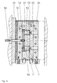
- contour plates 21, 22 are provided, in which the recesses 1 ', 1 "are made, which give the shape for a workpiece, here a ring 1.
- the contour plates 21, 22 are, however no longer - as in the prior art - screwed to the heating plates 23, 24, but are pressed into the working position (FIG. 3) by means of quick-release elements 27 on the heating plates 23, 24, ie are releasably connected to them
- the quick-action clamping elements 27 also have pivot levers 31, as can be seen in FIG Rotation by 90 ° in the counterclockwise direction, the pressing lugs 28 are brought out of engagement with the pressing surfaces 29 and the contour plates 21, 22 are thus separated or released from the carrier plates 23, 24
- the quick release elements 27 are rotatably received by means of pins 32 in holding blocks 33, which in turn are screwed to the carrier plates 23 and 24 by means of screws 34.
- a quickly detachable and quickly recoverable Connection of the carrier and contour plates is also with others Connection facilities possible.
- the carrier plate is inside the left tool half 25 23 with the insulating plate 35 and the base plate 36 screwed. This in turn is part of the plate 7 the injection molding machine is screwed. In detail are these screw connections are not all executed. An expert however, based on the information provided, it is clear how that he follows.
- the contour plate is within the right tool half 26 22 by means of quick release elements 27 with the carrier plate 24 releasably connected, the quick release element 27 with the Heating plate 24 is screwed.
- the radiators 38 which are arranged in the bores 39 of the carrier plates, are shown in dashed lines.
- the carrier plates are heated in the execution examples explained here, that is, designed as heating plates.
- thermoplastics they are cooled, i.e. they are designed as cooling plates.
- the contour plates 21, 22 can be separated from the underlying carrier plates 23, 24 and replaced as a unit after a simple loosening of the quick-action clamping elements 27, as shown in FIG. This means that only the contour plates 21, 22 have to be exchanged for different workpieces, so that the remaining parts of the tool, ie carrier plates and insulating plates, remain in the injection molding machine within certain product groups.
- Steps (a) to (e) of the tool exchange process are shown schematically in FIGS. 14/1 and 14/2.
- the contour plates 21 detach from the carrier plates 23 and 24, respectively.
- the contour plates 21 and 22 can immediately be removed as a unit and placed elsewhere for cooling.
- - Figure 14/2 (d) - new contour plates 21 ', 22' are inserted and fixed after the machine has been moved together by the quick-action clamping elements, see Figure 14/2 (e).
- Centering means 40, 41 are provided on the two contour plates 21, 22 (see FIGS. 3 to 5), which center the contour plates upon moving the machine to each other.
- the centering means are formed by projections and recesses which are matched to one another.
- centering means 42, 43 and 46, 47 are provided for centering the contour plates to the carrier plates 23, 24 when the tool is exchanged , which, in cooperation, form a cross centering .
- Such a centering unit is a total of four times, ie on each of the two axes of symmetry, x-axis and y-axis, each contour plate provided twice.
- the two centering units 42, 43 are along the y axis, that is, symmetrical to the x-axis. They center in x direction, since they don't expand in that direction, because the x-axis is the axis of symmetry. They have in the y direction however game so that they correspond to the Can shift thermal expansion against each other.
- the Centering units 46, 47 are symmetrical on the x-axis to the y-axis, provided and center in the y-direction while them in the direction of thermal expansion, in the x direction, play to have.
- the centering units along the x-axis are marked by a block 46 and a groove 47 are formed.
- the workpiece 2 is in this embodiment Brushes 20 demolded.
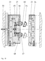
- the workpieces are ejected, which is realized by an ejector pin 50, an ejector plate 51 and ejector pins 53 fastened thereon by means of a further holding plate 52.
- the ejector pin 50 and the ejector plate 51 move in a recess 56 in the contour plate 21 which is open towards the carrier plate 23.
- the ejector plates can also be arranged behind the carrier plate.
- the ejector pin 50 is actuated from the machine side after the injection molding machine has opened. The ejector remains in the machine when the contour plates 21 and 22 are exchanged as a unit.
- the third exemplary embodiment according to FIGS. 8 and 9 shows the demolding by means of a scraper plate 54, which is also connected to an ejector pin 50 and is actuated from the machine side after the injection molding machine has been opened.
- the tool is somewhat different from that of FIGS. 3 to 7, in that a mandrel 55 is provided which projects into the recess 1 "in the contour plate 22 and together with the recess and the contour plate the shape for the workpiece, in the example case defines a ring 1 (see FIG. 9)
- the stripper plate 54 is received in a recess 56 which is open towards the center of the machine, ie towards the other contour plate 22.
- the fourth exemplary embodiment according to FIGS. 10 and 11 shows the demolding by means of a pushing-out or a blowing-out device.
- the workpiece is an annular sealing ring 57 provided with two lips.
- the shape for the workpiece is determined by the contour of the mold plate 58, which is fastened to the ejector bolt 50, the mold core 55, by the base surface 59 of the recess 71 and the end face 60 of the contour plate 22 formed.
- the ejector pin 50 moves into the Position shown in Figure 11 so that the ejector plate 58, in which the workpiece 57 is located, from the recess 71 is pulled out. Now either one from the outside Push-out device 61 retracted (arrow 62) and then like this moves (arrow 63) that the workpiece 57 from the Form plate 58 pushes out ( Figure 11, upper half), or - as an alternative - a blow-out device 61 from the side retracted here and then pressurized with compressed air so that it blows the workpiece 57 out of the mold plate 58.
- the Examples of the invention shown above can each according to the geometry and problem of the workpiece combine as shown below.
- the fifth exemplary embodiment according to FIGS. 12 and 13 shows a tool for injecting a cap 64, which is removed from the mold by a combination of blowing out and ejecting.
- An ejector plate 51 and a holding plate 52, on which valve ejector pins 65 are fastened, are seated on the ejector pin 50. They can be moved in the opening 66 'of a mold core 66 which is arranged in the mold plate 21. Compressed air is supplied to the annular gap 67 between the opening 66 'and the valve ejector pin 65 via the line 68.
- the ejector plate 51 moves in a recess 69 in the contour plate 21 and presses the head of the valve ejector pins 65 against the cap 64 from the inside. At the same time, this ejection movement is supported by the compressed air, which then emerges from the annular gap 67 in the mandrel 66.
Landscapes
- Engineering & Computer Science (AREA)
- Mechanical Engineering (AREA)
- Manufacturing & Machinery (AREA)
- Moulds For Moulding Plastics Or The Like (AREA)
- Diaphragms For Electromechanical Transducers (AREA)
- Encapsulation Of And Coatings For Semiconductor Or Solid State Devices (AREA)
Claims (15)
- Moule pour moulage par injection ou moulage sous pression, formé par deux demi-moules (25, 26) qui sont susceptibles d'être assemblés avec les plaques (6, 7) d'une presse d'injection et sont munis chacun d'une plaque de support (23, 24) et d'une plaque de formage (21, 22), les plaques de formage (21, 22) comportant des évidements (1', 1") qui, conjointement, permettent d'obtenir la forme de la pièce moulée (1), et pouvant être assemblées avec les plaques de support par des éléments de serrage (27, 28), dans lequel sont prévus en outre des dispositifs (38, 39) pour chauffer ou refroidir les demi-moules, caractérisé en ce que les dispositifs de chauffage et de refroidissement (38, 39) sont prévus dans les plaques de support (23, 34) et en ce que des premiers moyens de centrage (42, 43 ; 46, 47), agissant dans le sens x et y, sont prévus respectivement entre les plaques de formage (21, 22) et la plaque de support (23, 24) qui leur est associée et des deuxièmes moyens de centrage (40, 41), agissant dans le sens x et y, sont prévus entre les deux plaques de formage (21, 22).
- Moule selon la revendication 1, caractérisé en ce qu'au moins une plaque de formage (22) comporte au moins un orifice (15'), à travers lequel passe une buse (15) destinée à l'admission de la matière, qui s'étend jusque dans l'évidement (1', 1").
- Moule selon la revendication 1 ou 2, caractérisé en ce que les éléments de serrage (27) sont disposés de manière rotative contre les plaques (6, 7), mobiles l'une par rapport à l'autre, de la presse d'injection ou de la machine de moulage sous pression ou contre les plaques de support (23, 24).
- Moule selon la revendication 3, caractérisé en ce que les éléments de serrage comportent des taquets de pression (28), qui agissent sur des surfaces de pression (29) dans des évidements (30) des plaques de formage (21, 22) et qui peuvent pivoter vers cette position, ainsi que hors de celle-ci.
- Moule selon la revendication 1 ou l'une des revendications suivantes, caractérisé en ce que les deux plaques de formage (21, 22) peuvent être assemblées conjointement avec un dispositif de manipulation (37).
- Moule selon la revendication 1 ou l'une des revendications suivantes, caractérisé en ce que dans le côté d'une plaque de formage (21), opposé à l'autre plaque de formage (22) ou dans la plaque de support disposée derrière celle-ci est prévu un évidement (56) dans lequel peut coulisser un élément d'éjection (50 à 53) et dont l'élément de commande (50) s'étend à travers des orifices réalisés dans la plaque de support (23), et en ce que les éléments d'éjection (53) peuvent coulisser à travers des orifices réalisés dans la plaque de formage (21).
- Moule selon la revendication 1 ou l'une des revendications suivantes, caractérisé en ce que dans le côté d'une plaque de formage (21), orienté vers l'autre plaque de formage (22), est prévu un évidement (56) dans lequel peut coulisser un élément de démoulage (54), dont l'élément de commande (50) s'étend à travers des orifices réalisés dans la plaque de support (23) et dans la plaque de formage (21).
- Moule selon la revendication 1 ou l'une des revendications suivantes, caractérisé en ce qu'un noyau du moule (55) est agencé dans la plaque de formage (21), lequel coopère avec les évidements (1', 1") dans la plaque de formage (21, 22) pour obtenir la forme de la pièce moulée (57).
- Moule selon la revendication 1 ou l'une des revendications suivantes, caractérisé en ce que la forme de la pièce moulée est obtenue partiellement par une plaque-modèle, qui peut coulisser dans un évidement (71) de la plaque de formage (21) et dont l'élément de commande (50) s'étend à travers la plaque de support (23) et la plaque de formage (21), et en ce que, lorsque la plaque-modèle est extraite de l'évidement (71), la pièce moulée (57) est démoulée au moyen d'un élément éjecteur (61) ou d'un élément à buse éjectrice (61').
- Moule selon la revendication 1 ou l'une des revendications suivantes, caractérisé en ce que sur le côté de la plaque de formage (21) orienté vers l'autre plaque de formage (22) est agencé un noyau du moule (66), à travers lequel s'étend une tige d'éjection (65), dont l'extrémité (65') est conçue sous forme de corps de soupape, par lequel la fente annulaire (67) entre la tige d'éjection (65) et le noyau du moule (66) est obturée et elle est dégagée lorsque ledit corps de soupape est actionné par un élément de commande (50), en ce que de l'air comprimé est acheminé vers la fente annulaire (67) et en ce que l'élément de commande (50) s'étend à travers la plaque de support (23).
- Moule selon la revendication 1 ou l'une des revendications suivantes, caractérisé par des moyens de centrage (42, 43 ; 46, 47) disposés en croix pour l'ajustement des plaques de formage (21, 22) au niveau des plaques de support (23, 24).
- Moule selon la revendication 11, caractérisé en ce que des premiers moyens de centrage (46, 47) entre une plaque de formage (21, 22) et une plaque de support (23, 24) sont prévus le long d'un premier axe de symétrie (axe des x) du moule et des plaques de formage (21, 22) ou des plaques de support (23, 24), lesquels, pour permettre un mouvement relatif de la plaque de formage par rapport à la plaque de support, sont conçus avec un jeu dans le sens de ce premier axe de symétrie, mais pas dans le sens perpendiculaire à celui-ci (sens de l'axe des y), et en ce que des deuxièmes moyens de centrage (42, 43) sont prévus le long d'un deuxième axe de symétrie (axe des y), lesquels sont conçus avec un jeu dans le sens de ce deuxième axe de symétrie, mais pas dans le sens perpendiculaire à celui-ci (sens de l'axe des x).
- Moule selon la revendication 11 ou 12, caractérisé en ce que les moyens de centrage sont formés par un boulon (42, 46), qui est disposé au niveau de l'un des composants de la plaque de formage/plaque de support et qui peut coulisser dans l'autre composant de la plaque de formage/plaque de support dans un sens (42') permettant de garantir le jeu et est logé sans jeu dans l'autre sens (42").
- Moule selon la revendication 11, 12 ou 13,
caractérisé en ce qu'il est prévu au moins trois moyens de centrage, deux moyens de centrage étant agencés le long de l'un des axes de symétrie et au moins un autre moyen de centrage étant agencé le long de l'autre axe de symétrie. - Procédé pour le remplacement d'un moule pour moulage par injection ou d'un moule pour injection sous pression, qui est formé par deux demi-moules (25, 26), qui sont munis chacun de dispositifs de chauffage (38, 39), d'une plaque de support (23, 24) et d'une plaque de formage (21, 22) pouvant être bloquée sur celle-ci au moyen d'éléments de serrage (27), les demi-moules (25, 26) pouvant être fixés contre les plaques, mobiles l'une par rapport à l'autre, d'une presse d'injection ou d'une machine de moulage sous pression, caractérisé en ce que(a) lorsque la presse d'injection est en position insérée, les plaques de formage (21, 22) sont assemblées conjointement avec un dispositif de transport (37) ; ensuite(b) l'assemblage entre les plaques de formage (21, 22) et les plaques de support (23, 24), réalisé au moyen des éléments de serrage (27, 28), est désolidarisé ; ensuite(c) la presse d'injection est amenée en position extraite, dans laquelle les plaques de formage (21, 22) assemblées conjointement avec le dispositif de transport (37) sont désolidarisées des plaques de support et sont éloignées de celles-ci ; ensuite(d) une autre paire de plaques de formage (21', 22'), qui sont assemblées au moyen d'un dispositif de transport (37), sont acheminées entre les plaques de support (23, 24) ; et ensuite(e) la presse d'injection est à nouveau amenée en position insérée, le dispositif de transport (37) est écarté et les plaques de formage (21', 22') sont assemblées avec les plaques de support (23, 24) au moyen des éléments de serrage (27).
Applications Claiming Priority (2)
| Application Number | Priority Date | Filing Date | Title |
|---|---|---|---|
| DE19731536A DE19731536C2 (de) | 1997-07-23 | 1997-07-23 | Werkzeug für Spritz- oder Druckguß |
| DE19731536 | 1997-07-23 |
Publications (3)
| Publication Number | Publication Date |
|---|---|
| EP0893221A2 EP0893221A2 (fr) | 1999-01-27 |
| EP0893221A3 EP0893221A3 (fr) | 2000-12-13 |
| EP0893221B1 true EP0893221B1 (fr) | 2003-02-12 |
Family
ID=7836568
Family Applications (1)
| Application Number | Title | Priority Date | Filing Date |
|---|---|---|---|
| EP98113463A Expired - Lifetime EP0893221B1 (fr) | 1997-07-23 | 1998-07-20 | Moule pour le moulage par injection ou compression |
Country Status (3)
| Country | Link |
|---|---|
| EP (1) | EP0893221B1 (fr) |
| AT (1) | ATE232443T1 (fr) |
| DE (2) | DE19731536C2 (fr) |
Families Citing this family (18)
| Publication number | Priority date | Publication date | Assignee | Title |
|---|---|---|---|---|
| DE19914439B4 (de) * | 1999-03-30 | 2006-11-02 | Volkswagen Ag | Guss-Kokille |
| DE19949851C2 (de) * | 1999-10-15 | 2001-09-13 | Hekuma Herbst Maschb Gmbh | Kunststoff-Spritzgießmaschine, Handlingsystem sowie Verfahren zum Überführen eines Gegenstandes |
| BR0111603A (pt) * | 2000-06-16 | 2003-05-06 | Dme Co | Dispositivo de engatamento para moldes de injeção com inserções removìveis |
| DE10033207C1 (de) * | 2000-07-07 | 2001-12-06 | Peter Derksen | Einsatzanordnung für ein Formwerkzeug sowie Formwerkzeug mit einer solchen |
| DE10045384B4 (de) * | 2000-09-14 | 2006-07-06 | Bayerische Motoren Werke Ag | Führungsvorrichtung |
| US8061005B2 (en) * | 2009-03-13 | 2011-11-22 | Carefusion 303, Inc. | Method for employing quick change injection molding tooling |
| DE202009018781U1 (de) * | 2009-09-02 | 2013-07-08 | Krones Ag | Vorrichtung zur Montage und/oder Demontage von Blasformen |
| DE102009039696A1 (de) | 2009-09-02 | 2011-03-24 | Krones Ag | Vorrichtung zum Umformen von Kunststoffbehältnissen mit einer Blasform |
| FR2949707A1 (fr) * | 2009-09-07 | 2011-03-11 | Sidel Participations | Dispositif de moulage pour une machine de fabrication de recipients, notamment des bouteilles |
| FR2949705B1 (fr) * | 2009-09-07 | 2016-09-16 | Sidel Participations | Dispositif de moulage equipe de moyens de fixation par accrochage d'un demi-moule sur un porte-moule |
| MX2012002242A (es) | 2009-09-07 | 2012-04-11 | Sidel Participations | Metodo para cambiar un molde. |
| FR2949708B1 (fr) * | 2009-09-07 | 2017-01-13 | Sidel Participations | Procede de changement d'un moule pour la fabrication de recipients et dispositifs de fixation pour la mise en oeuvre d'un tel procede |
| DE102015210300B4 (de) | 2015-06-03 | 2023-06-01 | Volkswagen Aktiengesellschaft | Verfahren zur Herstellung von Druckgussteilen und Druckgussform hierzu |
| DE102016011060A1 (de) | 2016-09-12 | 2018-03-15 | Preh Car Connect Gmbh | Gussstück, Baugruppe mit Gussstück, Gusswerkzeug und Gussverfahren |
| DE202019100162U1 (de) | 2019-01-14 | 2019-02-07 | bekuplast Gesellschaft mit beschränkter Haftung | Spritzgusswerkzeug für die Herstellung von Behältern aus Kunststoff |
| ES3014207T3 (en) * | 2020-07-15 | 2025-04-21 | Gerresheimer Regensburg Gmbh | Centering system |
| DE102023120189A1 (de) * | 2023-07-28 | 2025-01-30 | Elringklinger Ag | Aufnahme für ein Einsteckelement und Spritzgusswerkzeug |
| DE102023128064A1 (de) | 2023-10-13 | 2025-04-17 | CycleTemp GmbH | Verfahren zur Herstellung von gekühlten Gießwerkzeugen und Gießwerkzeug |
Family Cites Families (15)
| Publication number | Priority date | Publication date | Assignee | Title |
|---|---|---|---|---|
| GB1064268A (en) * | 1963-12-18 | 1967-04-05 | Desma Werke Gmbh | Improvements in injection-moulding or vulcanising apparatus |
| DE1908427A1 (de) * | 1969-02-20 | 1970-09-17 | Geyer & Co | Normaliensatz fuer Spritzgussformen |
| DE2233207B2 (de) * | 1972-07-06 | 1974-08-15 | Hasco-Normalien Hasenclever & Co, 5880 Luedenscheid | Ausrichtvorrichtung für Formelemente von Werkzeugformen |
| JPS58222827A (ja) * | 1982-06-22 | 1983-12-24 | Sumitomo Heavy Ind Ltd | 射出成形用金型の自動交換装置 |
| DE8309096U1 (de) * | 1983-03-26 | 1986-10-23 | Strack-Norma Gmbh, 5600 Wuppertal | Spritzgußform |
| US4500275A (en) * | 1983-12-23 | 1985-02-19 | Sharp Die & Mold Company, Inc., A Subsidiary Of R & R Plastic Material, Inc. | Quick change locator clamp assembly for plastic molding machine |
| JPH0346894Y2 (fr) * | 1986-12-16 | 1991-10-04 | ||
| DE3704913A1 (de) * | 1987-02-17 | 1988-08-25 | Rainer Huber Gmbh | Schnellspannvorrichtung fuer spritzgiessmaschinen |
| US4750876A (en) * | 1987-09-24 | 1988-06-14 | Motorola Inc. | Guide pin assemblies for use in mold presses |
| DE3932039A1 (de) * | 1989-09-26 | 1991-04-11 | Werner & Pfleiderer | Gummi-spritz-presse |
| DE3934495C1 (fr) * | 1989-10-16 | 1990-12-13 | Marianne 8780 Gemuenden De Wieser | |
| JP3114944B2 (ja) * | 1991-07-12 | 2000-12-04 | 株式会社スター精機 | 成形機における金型自動交換方法 |
| JP3183535B2 (ja) * | 1991-08-08 | 2001-07-09 | 株式会社スター精機 | 金型自動交換システムにおける金型自動固定装置 |
| DE4340661C1 (de) * | 1993-11-30 | 1995-08-17 | Armin Spiess | Handhabungssystem für Gießformen |
| DE19518480C2 (de) * | 1995-05-19 | 1997-07-17 | Krauss Maffei Ag | Vorrichtung zum Zentrieren der Werkzeuge für Spritzgießmaschinen |
-
1997
- 1997-07-23 DE DE19731536A patent/DE19731536C2/de not_active Expired - Fee Related
-
1998
- 1998-07-20 AT AT98113463T patent/ATE232443T1/de not_active IP Right Cessation
- 1998-07-20 EP EP98113463A patent/EP0893221B1/fr not_active Expired - Lifetime
- 1998-07-20 DE DE59807163T patent/DE59807163D1/de not_active Expired - Fee Related
Also Published As
| Publication number | Publication date |
|---|---|
| EP0893221A3 (fr) | 2000-12-13 |
| DE19731536A1 (de) | 1999-01-28 |
| EP0893221A2 (fr) | 1999-01-27 |
| DE19731536C2 (de) | 2000-05-18 |
| DE59807163D1 (de) | 2003-03-20 |
| ATE232443T1 (de) | 2003-02-15 |
Similar Documents
| Publication | Publication Date | Title |
|---|---|---|
| DE19731536C2 (de) | Werkzeug für Spritz- oder Druckguß | |
| DE69626025T2 (de) | Verbessertes schnellwechsel-formwerkzeug | |
| EP1035959B1 (fr) | Machine de moulage par injection comportant des moules pouvant etre deplaces, et dispositif de fixation et porte-moule destines a une telle machine de moulage par injection | |
| EP2607044B1 (fr) | Outil de moulage par injection et procédé de rééquipement d'un tel outil de moulage par injection dans une machine de moulage par injection | |
| DE69010477T2 (de) | Tandem-Spritzmaschine mit direkter Zufuhr zu Formen. | |
| DE68921902T2 (de) | Sequentielle Spritzgiessmaschine. | |
| EP0397674B1 (fr) | Procede et installation pour fabriquer des pieces moulees en matiere plastique | |
| DE102007051701B4 (de) | Vorrichtung und Verfahren zur Herstellung mehrkomponentiger Kunststoff-Formteile | |
| EP2625019B1 (fr) | Machine de moulage par injection | |
| DE102020106314B4 (de) | Spritzgießmaschine | |
| EP0074473A1 (fr) | Procédé et dispositif pour la fabrication de pièces de forme ou des objets en matière plastique | |
| EP3498451B1 (fr) | Machine de moulage par soufflage à accouplement de sol pouvant être actionné automatiquement | |
| DE1679963B2 (de) | Vorrichtung zum Steuern der Öffnungsund Schließbewegung der Halsformteile und der Abstreifeinrichtung bei einer Spritz blasmaschine | |
| DE102013216008A1 (de) | Spritzgießmaschine für mehrere Spritzgießvorgänge | |
| DE4227336C1 (de) | Kunststoff-Spritzgießmaschine | |
| DE3637166C2 (fr) | ||
| DE4432163A1 (de) | Vorrichtung zum Herstellen von Spritzguss-Formteilen | |
| DE3534937A1 (de) | Spritzgiessform fuer kunststoff-spritzgiessmaschine mit verriegelungseinrichtung | |
| DE19627176A1 (de) | Vorrichtung zum Spritzgießen | |
| DE4306892A1 (en) | Accurate alignment of mould parts for synthetics - has one half located in approximate position against spring before closing mould on mating projection | |
| EP0303834A1 (fr) | Moule d'injection | |
| DE4435012C1 (de) | Verfahren und Vorrichtung zum Herstellen von Kunststoffgegenständen aus thermoplastischem Material | |
| DE29724134U1 (de) | Werkzeug für Spritz- oder Druckguss | |
| DE29506094U1 (de) | Wechseleinrichtung von Spritzköpfen | |
| DE4021856A1 (de) | Spritzgiesswerkzeug |
Legal Events
| Date | Code | Title | Description |
|---|---|---|---|
| PUAI | Public reference made under article 153(3) epc to a published international application that has entered the european phase |
Free format text: ORIGINAL CODE: 0009012 |
|
| AK | Designated contracting states |
Kind code of ref document: A2 Designated state(s): AT BE CH CY DE DK ES FI FR GB GR IE IT LI LU MC NL PT SE |
|
| AX | Request for extension of the european patent |
Free format text: AL;LT;LV;MK;RO;SI |
|
| PUAL | Search report despatched |
Free format text: ORIGINAL CODE: 0009013 |
|
| AK | Designated contracting states |
Kind code of ref document: A3 Designated state(s): AT BE CH CY DE DK ES FI FR GB GR IE IT LI LU MC NL PT SE |
|
| AX | Request for extension of the european patent |
Free format text: AL;LT;LV;MK;RO;SI |
|
| 17P | Request for examination filed |
Effective date: 20010605 |
|
| AKX | Designation fees paid |
Free format text: AT BE CH CY DE DK ES FI FR GB GR IE IT LI LU MC NL PT SE |
|
| 17Q | First examination report despatched |
Effective date: 20011116 |
|
| GRAG | Despatch of communication of intention to grant |
Free format text: ORIGINAL CODE: EPIDOS AGRA |
|
| GRAG | Despatch of communication of intention to grant |
Free format text: ORIGINAL CODE: EPIDOS AGRA |
|
| GRAH | Despatch of communication of intention to grant a patent |
Free format text: ORIGINAL CODE: EPIDOS IGRA |
|
| GRAH | Despatch of communication of intention to grant a patent |
Free format text: ORIGINAL CODE: EPIDOS IGRA |
|
| GRAA | (expected) grant |
Free format text: ORIGINAL CODE: 0009210 |
|
| AK | Designated contracting states |
Designated state(s): AT BE CH CY DE DK ES FI FR GB GR IE IT LI LU MC NL PT SE |
|
| PG25 | Lapsed in a contracting state [announced via postgrant information from national office to epo] |
Ref country code: IE Free format text: LAPSE BECAUSE OF FAILURE TO SUBMIT A TRANSLATION OF THE DESCRIPTION OR TO PAY THE FEE WITHIN THE PRESCRIBED TIME-LIMIT Effective date: 20030212 Ref country code: GR Free format text: LAPSE BECAUSE OF FAILURE TO SUBMIT A TRANSLATION OF THE DESCRIPTION OR TO PAY THE FEE WITHIN THE PRESCRIBED TIME-LIMIT Effective date: 20030212 Ref country code: GB Free format text: LAPSE BECAUSE OF FAILURE TO SUBMIT A TRANSLATION OF THE DESCRIPTION OR TO PAY THE FEE WITHIN THE PRESCRIBED TIME-LIMIT Effective date: 20030212 Ref country code: FR Free format text: LAPSE BECAUSE OF FAILURE TO SUBMIT A TRANSLATION OF THE DESCRIPTION OR TO PAY THE FEE WITHIN THE PRESCRIBED TIME-LIMIT Effective date: 20030212 Ref country code: FI Free format text: LAPSE BECAUSE OF FAILURE TO SUBMIT A TRANSLATION OF THE DESCRIPTION OR TO PAY THE FEE WITHIN THE PRESCRIBED TIME-LIMIT Effective date: 20030212 |
|
| REG | Reference to a national code |
Ref country code: GB Ref legal event code: FG4D Free format text: NOT ENGLISH |
|
| REG | Reference to a national code |
Ref country code: CH Ref legal event code: EP |
|
| REF | Corresponds to: |
Ref document number: 59807163 Country of ref document: DE Date of ref document: 20030320 Kind code of ref document: P |
|
| PG25 | Lapsed in a contracting state [announced via postgrant information from national office to epo] |
Ref country code: SE Free format text: LAPSE BECAUSE OF FAILURE TO SUBMIT A TRANSLATION OF THE DESCRIPTION OR TO PAY THE FEE WITHIN THE PRESCRIBED TIME-LIMIT Effective date: 20030512 Ref country code: PT Free format text: LAPSE BECAUSE OF FAILURE TO SUBMIT A TRANSLATION OF THE DESCRIPTION OR TO PAY THE FEE WITHIN THE PRESCRIBED TIME-LIMIT Effective date: 20030512 Ref country code: DK Free format text: LAPSE BECAUSE OF FAILURE TO SUBMIT A TRANSLATION OF THE DESCRIPTION OR TO PAY THE FEE WITHIN THE PRESCRIBED TIME-LIMIT Effective date: 20030512 |
|
| REG | Reference to a national code |
Ref country code: CH Ref legal event code: NV Representative=s name: SAEGER & PARTNER |
|
| REG | Reference to a national code |
Ref country code: IE Ref legal event code: FG4D Free format text: GERMAN |
|
| PG25 | Lapsed in a contracting state [announced via postgrant information from national office to epo] |
Ref country code: LU Free format text: LAPSE BECAUSE OF NON-PAYMENT OF DUE FEES Effective date: 20030720 Ref country code: CY Free format text: LAPSE BECAUSE OF FAILURE TO SUBMIT A TRANSLATION OF THE DESCRIPTION OR TO PAY THE FEE WITHIN THE PRESCRIBED TIME-LIMIT Effective date: 20030720 |
|
| PG25 | Lapsed in a contracting state [announced via postgrant information from national office to epo] |
Ref country code: MC Free format text: LAPSE BECAUSE OF NON-PAYMENT OF DUE FEES Effective date: 20030731 |
|
| GBV | Gb: ep patent (uk) treated as always having been void in accordance with gb section 77(7)/1977 [no translation filed] |
Effective date: 20030212 |
|
| PG25 | Lapsed in a contracting state [announced via postgrant information from national office to epo] |
Ref country code: ES Free format text: LAPSE BECAUSE OF FAILURE TO SUBMIT A TRANSLATION OF THE DESCRIPTION OR TO PAY THE FEE WITHIN THE PRESCRIBED TIME-LIMIT Effective date: 20030828 |
|
| REG | Reference to a national code |
Ref country code: IE Ref legal event code: FD4D Ref document number: 0893221E Country of ref document: IE |
|
| PLBE | No opposition filed within time limit |
Free format text: ORIGINAL CODE: 0009261 |
|
| STAA | Information on the status of an ep patent application or granted ep patent |
Free format text: STATUS: NO OPPOSITION FILED WITHIN TIME LIMIT |
|
| EN | Fr: translation not filed | ||
| PGFP | Annual fee paid to national office [announced via postgrant information from national office to epo] |
Ref country code: NL Payment date: 20040131 Year of fee payment: 6 |
|
| PGFP | Annual fee paid to national office [announced via postgrant information from national office to epo] |
Ref country code: DE Payment date: 20040202 Year of fee payment: 6 Ref country code: BE Payment date: 20040202 Year of fee payment: 6 |
|
| 26N | No opposition filed |
Effective date: 20031113 |
|
| PGFP | Annual fee paid to national office [announced via postgrant information from national office to epo] |
Ref country code: AT Payment date: 20040211 Year of fee payment: 6 |
|
| PGFP | Annual fee paid to national office [announced via postgrant information from national office to epo] |
Ref country code: CH Payment date: 20040217 Year of fee payment: 6 |
|
| REG | Reference to a national code |
Ref country code: CH Ref legal event code: PL Ref country code: CH Ref legal event code: AEN Free format text: DAS PATENT IST AUFGRUND DES WEITERBEHANDLUNGSANTRAGS VOM 10.02.2004 REAKTIVIERT WORDEN. |
|
| PG25 | Lapsed in a contracting state [announced via postgrant information from national office to epo] |
Ref country code: AT Free format text: LAPSE BECAUSE OF NON-PAYMENT OF DUE FEES Effective date: 20040720 |
|
| PG25 | Lapsed in a contracting state [announced via postgrant information from national office to epo] |
Ref country code: LI Free format text: LAPSE BECAUSE OF NON-PAYMENT OF DUE FEES Effective date: 20040731 Ref country code: CH Free format text: LAPSE BECAUSE OF NON-PAYMENT OF DUE FEES Effective date: 20040731 Ref country code: BE Free format text: LAPSE BECAUSE OF NON-PAYMENT OF DUE FEES Effective date: 20040731 |
|
| BERE | Be: lapsed |
Owner name: *EDEGS FORMENBAU G.M.B.H. Effective date: 20040731 |
|
| PG25 | Lapsed in a contracting state [announced via postgrant information from national office to epo] |
Ref country code: NL Free format text: LAPSE BECAUSE OF NON-PAYMENT OF DUE FEES Effective date: 20050201 Ref country code: DE Free format text: LAPSE BECAUSE OF NON-PAYMENT OF DUE FEES Effective date: 20050201 |
|
| REG | Reference to a national code |
Ref country code: CH Ref legal event code: PL |
|
| NLV4 | Nl: lapsed or anulled due to non-payment of the annual fee |
Effective date: 20050201 |
|
| PG25 | Lapsed in a contracting state [announced via postgrant information from national office to epo] |
Ref country code: IT Free format text: LAPSE BECAUSE OF NON-PAYMENT OF DUE FEES Effective date: 20050720 |
|
| BERE | Be: lapsed |
Owner name: *EDEGS FORMENBAU G.M.B.H. Effective date: 20040731 |