EP0893223B1 - Verfahren zum herstellen einer nahtlosen gravurwalze zur herstellung von folien mit optischen effekten, und anlage mit einer solchen gravurwalze - Google Patents
Verfahren zum herstellen einer nahtlosen gravurwalze zur herstellung von folien mit optischen effekten, und anlage mit einer solchen gravurwalze Download PDFInfo
- Publication number
- EP0893223B1 EP0893223B1 EP97942963A EP97942963A EP0893223B1 EP 0893223 B1 EP0893223 B1 EP 0893223B1 EP 97942963 A EP97942963 A EP 97942963A EP 97942963 A EP97942963 A EP 97942963A EP 0893223 B1 EP0893223 B1 EP 0893223B1
- Authority
- EP
- European Patent Office
- Prior art keywords
- engraving
- cylinder
- plant
- polymerising
- sheet
- Prior art date
- Legal status (The legal status is an assumption and is not a legal conclusion. Google has not performed a legal analysis and makes no representation as to the accuracy of the status listed.)
- Expired - Lifetime
Links
- 230000003287 optical effect Effects 0.000 title claims abstract description 14
- 238000000034 method Methods 0.000 title claims description 15
- 239000011347 resin Substances 0.000 claims abstract description 26
- 229920005989 resin Polymers 0.000 claims abstract description 26
- 238000007639 printing Methods 0.000 claims abstract description 17
- 238000007647 flexography Methods 0.000 claims abstract description 4
- 239000000463 material Substances 0.000 claims description 6
- 239000003086 colorant Substances 0.000 claims description 5
- 238000000465 moulding Methods 0.000 claims description 5
- 239000004033 plastic Substances 0.000 claims description 5
- 229920003023 plastic Polymers 0.000 claims description 5
- 238000000151 deposition Methods 0.000 claims 1
- 238000006116 polymerization reaction Methods 0.000 abstract 2
- PXHVJJICTQNCMI-UHFFFAOYSA-N Nickel Chemical compound [Ni] PXHVJJICTQNCMI-UHFFFAOYSA-N 0.000 description 8
- 238000004519 manufacturing process Methods 0.000 description 5
- 229910052751 metal Inorganic materials 0.000 description 5
- 239000002184 metal Substances 0.000 description 5
- 229910052759 nickel Inorganic materials 0.000 description 4
- 229920001296 polysiloxane Polymers 0.000 description 4
- 238000010276 construction Methods 0.000 description 3
- 230000000694 effects Effects 0.000 description 3
- 238000005323 electroforming Methods 0.000 description 3
- 238000010348 incorporation Methods 0.000 description 3
- 238000001465 metallisation Methods 0.000 description 3
- 239000000853 adhesive Substances 0.000 description 2
- 230000001070 adhesive effect Effects 0.000 description 2
- 239000011248 coating agent Substances 0.000 description 2
- 238000000576 coating method Methods 0.000 description 2
- 239000000839 emulsion Substances 0.000 description 2
- 239000010985 leather Substances 0.000 description 2
- 230000002093 peripheral effect Effects 0.000 description 2
- 238000005096 rolling process Methods 0.000 description 2
- 239000000758 substrate Substances 0.000 description 2
- CERQOIWHTDAKMF-UHFFFAOYSA-M Methacrylate Chemical compound CC(=C)C([O-])=O CERQOIWHTDAKMF-UHFFFAOYSA-M 0.000 description 1
- 229920001944 Plastisol Polymers 0.000 description 1
- RTAQQCXQSZGOHL-UHFFFAOYSA-N Titanium Chemical compound [Ti] RTAQQCXQSZGOHL-UHFFFAOYSA-N 0.000 description 1
- 238000005452 bending Methods 0.000 description 1
- 230000015572 biosynthetic process Effects 0.000 description 1
- 230000002860 competitive effect Effects 0.000 description 1
- 230000000295 complement effect Effects 0.000 description 1
- 230000008878 coupling Effects 0.000 description 1
- 238000010168 coupling process Methods 0.000 description 1
- 238000005859 coupling reaction Methods 0.000 description 1
- 230000001419 dependent effect Effects 0.000 description 1
- 238000005304 joining Methods 0.000 description 1
- 239000007788 liquid Substances 0.000 description 1
- 230000036961 partial effect Effects 0.000 description 1
- 230000035515 penetration Effects 0.000 description 1
- 239000004999 plastisol Substances 0.000 description 1
- 229920000728 polyester Polymers 0.000 description 1
- 239000010453 quartz Substances 0.000 description 1
- VYPSYNLAJGMNEJ-UHFFFAOYSA-N silicon dioxide Inorganic materials O=[Si]=O VYPSYNLAJGMNEJ-UHFFFAOYSA-N 0.000 description 1
- 239000000126 substance Substances 0.000 description 1
- 229920001169 thermoplastic Polymers 0.000 description 1
- 239000004416 thermosoftening plastic Substances 0.000 description 1
- 239000010936 titanium Substances 0.000 description 1
- 229910052719 titanium Inorganic materials 0.000 description 1
- 238000003466 welding Methods 0.000 description 1
Images



Classifications
-
- B—PERFORMING OPERATIONS; TRANSPORTING
- B29—WORKING OF PLASTICS; WORKING OF SUBSTANCES IN A PLASTIC STATE IN GENERAL
- B29C—SHAPING OR JOINING OF PLASTICS; SHAPING OF MATERIAL IN A PLASTIC STATE, NOT OTHERWISE PROVIDED FOR; AFTER-TREATMENT OF THE SHAPED PRODUCTS, e.g. REPAIRING
- B29C35/00—Heating, cooling or curing, e.g. crosslinking or vulcanising; Apparatus therefor
- B29C35/02—Heating or curing, e.g. crosslinking or vulcanizing during moulding, e.g. in a mould
- B29C35/08—Heating or curing, e.g. crosslinking or vulcanizing during moulding, e.g. in a mould by wave energy or particle radiation
- B29C35/10—Heating or curing, e.g. crosslinking or vulcanizing during moulding, e.g. in a mould by wave energy or particle radiation for articles of indefinite length
-
- B—PERFORMING OPERATIONS; TRANSPORTING
- B29—WORKING OF PLASTICS; WORKING OF SUBSTANCES IN A PLASTIC STATE IN GENERAL
- B29C—SHAPING OR JOINING OF PLASTICS; SHAPING OF MATERIAL IN A PLASTIC STATE, NOT OTHERWISE PROVIDED FOR; AFTER-TREATMENT OF THE SHAPED PRODUCTS, e.g. REPAIRING
- B29C39/00—Shaping by casting, i.e. introducing the moulding material into a mould or between confining surfaces without significant moulding pressure; Apparatus therefor
- B29C39/14—Shaping by casting, i.e. introducing the moulding material into a mould or between confining surfaces without significant moulding pressure; Apparatus therefor for making articles of indefinite length
- B29C39/148—Shaping by casting, i.e. introducing the moulding material into a mould or between confining surfaces without significant moulding pressure; Apparatus therefor for making articles of indefinite length characterised by the shape of the surface
-
- B—PERFORMING OPERATIONS; TRANSPORTING
- B29—WORKING OF PLASTICS; WORKING OF SUBSTANCES IN A PLASTIC STATE IN GENERAL
- B29C—SHAPING OR JOINING OF PLASTICS; SHAPING OF MATERIAL IN A PLASTIC STATE, NOT OTHERWISE PROVIDED FOR; AFTER-TREATMENT OF THE SHAPED PRODUCTS, e.g. REPAIRING
- B29C59/00—Surface shaping of articles, e.g. embossing; Apparatus therefor
- B29C59/002—Component parts, details or accessories; Auxiliary operations
-
- B—PERFORMING OPERATIONS; TRANSPORTING
- B29—WORKING OF PLASTICS; WORKING OF SUBSTANCES IN A PLASTIC STATE IN GENERAL
- B29C—SHAPING OR JOINING OF PLASTICS; SHAPING OF MATERIAL IN A PLASTIC STATE, NOT OTHERWISE PROVIDED FOR; AFTER-TREATMENT OF THE SHAPED PRODUCTS, e.g. REPAIRING
- B29C59/00—Surface shaping of articles, e.g. embossing; Apparatus therefor
- B29C59/02—Surface shaping of articles, e.g. embossing; Apparatus therefor by mechanical means, e.g. pressing
- B29C59/04—Surface shaping of articles, e.g. embossing; Apparatus therefor by mechanical means, e.g. pressing using rollers or endless belts
-
- B—PERFORMING OPERATIONS; TRANSPORTING
- B29—WORKING OF PLASTICS; WORKING OF SUBSTANCES IN A PLASTIC STATE IN GENERAL
- B29D—PRODUCING PARTICULAR ARTICLES FROM PLASTICS OR FROM SUBSTANCES IN A PLASTIC STATE
- B29D11/00—Producing optical elements, e.g. lenses or prisms
-
- B—PERFORMING OPERATIONS; TRANSPORTING
- B29—WORKING OF PLASTICS; WORKING OF SUBSTANCES IN A PLASTIC STATE IN GENERAL
- B29D—PRODUCING PARTICULAR ARTICLES FROM PLASTICS OR FROM SUBSTANCES IN A PLASTIC STATE
- B29D99/00—Subject matter not provided for in other groups of this subclass
- B29D99/0032—Producing rolling bodies, e.g. rollers, wheels, pulleys or pinions
- B29D99/0035—Producing rolling bodies, e.g. rollers, wheels, pulleys or pinions rollers or cylinders having an axial length of several times the diameter, e.g. for embossing, pressing, or printing
-
- G—PHYSICS
- G01—MEASURING; TESTING
- G01R—MEASURING ELECTRIC VARIABLES; MEASURING MAGNETIC VARIABLES
- G01R31/00—Arrangements for testing electric properties; Arrangements for locating electric faults; Arrangements for electrical testing characterised by what is being tested not provided for elsewhere
- G01R31/28—Testing of electronic circuits, e.g. by signal tracer
- G01R31/2851—Testing of integrated circuits [IC]
-
- G—PHYSICS
- G01—MEASURING; TESTING
- G01R—MEASURING ELECTRIC VARIABLES; MEASURING MAGNETIC VARIABLES
- G01R31/00—Arrangements for testing electric properties; Arrangements for locating electric faults; Arrangements for electrical testing characterised by what is being tested not provided for elsewhere
- G01R31/28—Testing of electronic circuits, e.g. by signal tracer
- G01R31/2851—Testing of integrated circuits [IC]
- G01R31/2893—Handling, conveying or loading, e.g. belts, boats, vacuum fingers
-
- G—PHYSICS
- G01—MEASURING; TESTING
- G01R—MEASURING ELECTRIC VARIABLES; MEASURING MAGNETIC VARIABLES
- G01R31/00—Arrangements for testing electric properties; Arrangements for locating electric faults; Arrangements for electrical testing characterised by what is being tested not provided for elsewhere
- G01R31/28—Testing of electronic circuits, e.g. by signal tracer
- G01R31/317—Testing of digital circuits
- G01R31/3181—Functional testing
- G01R31/319—Tester hardware, i.e. output processing circuits
- G01R31/31903—Tester hardware, i.e. output processing circuits tester configuration
-
- B—PERFORMING OPERATIONS; TRANSPORTING
- B29—WORKING OF PLASTICS; WORKING OF SUBSTANCES IN A PLASTIC STATE IN GENERAL
- B29C—SHAPING OR JOINING OF PLASTICS; SHAPING OF MATERIAL IN A PLASTIC STATE, NOT OTHERWISE PROVIDED FOR; AFTER-TREATMENT OF THE SHAPED PRODUCTS, e.g. REPAIRING
- B29C35/00—Heating, cooling or curing, e.g. crosslinking or vulcanising; Apparatus therefor
- B29C35/02—Heating or curing, e.g. crosslinking or vulcanizing during moulding, e.g. in a mould
- B29C35/08—Heating or curing, e.g. crosslinking or vulcanizing during moulding, e.g. in a mould by wave energy or particle radiation
- B29C35/0805—Heating or curing, e.g. crosslinking or vulcanizing during moulding, e.g. in a mould by wave energy or particle radiation using electromagnetic radiation
- B29C2035/0827—Heating or curing, e.g. crosslinking or vulcanizing during moulding, e.g. in a mould by wave energy or particle radiation using electromagnetic radiation using UV radiation
-
- B—PERFORMING OPERATIONS; TRANSPORTING
- B29—WORKING OF PLASTICS; WORKING OF SUBSTANCES IN A PLASTIC STATE IN GENERAL
- B29C—SHAPING OR JOINING OF PLASTICS; SHAPING OF MATERIAL IN A PLASTIC STATE, NOT OTHERWISE PROVIDED FOR; AFTER-TREATMENT OF THE SHAPED PRODUCTS, e.g. REPAIRING
- B29C35/00—Heating, cooling or curing, e.g. crosslinking or vulcanising; Apparatus therefor
- B29C35/02—Heating or curing, e.g. crosslinking or vulcanizing during moulding, e.g. in a mould
- B29C35/08—Heating or curing, e.g. crosslinking or vulcanizing during moulding, e.g. in a mould by wave energy or particle radiation
- B29C35/0866—Heating or curing, e.g. crosslinking or vulcanizing during moulding, e.g. in a mould by wave energy or particle radiation using particle radiation
- B29C2035/0877—Heating or curing, e.g. crosslinking or vulcanizing during moulding, e.g. in a mould by wave energy or particle radiation using particle radiation using electron radiation, e.g. beta-rays
-
- B—PERFORMING OPERATIONS; TRANSPORTING
- B29—WORKING OF PLASTICS; WORKING OF SUBSTANCES IN A PLASTIC STATE IN GENERAL
- B29K—INDEXING SCHEME ASSOCIATED WITH SUBCLASSES B29B, B29C OR B29D, RELATING TO MOULDING MATERIALS OR TO MATERIALS FOR MOULDS, REINFORCEMENTS, FILLERS OR PREFORMED PARTS, e.g. INSERTS
- B29K2883/00—Use of polymers having silicon, with or without sulfur, nitrogen, oxygen, or carbon only, in the main chain, as mould material
-
- B—PERFORMING OPERATIONS; TRANSPORTING
- B29—WORKING OF PLASTICS; WORKING OF SUBSTANCES IN A PLASTIC STATE IN GENERAL
- B29K—INDEXING SCHEME ASSOCIATED WITH SUBCLASSES B29B, B29C OR B29D, RELATING TO MOULDING MATERIALS OR TO MATERIALS FOR MOULDS, REINFORCEMENTS, FILLERS OR PREFORMED PARTS, e.g. INSERTS
- B29K2995/00—Properties of moulding materials, reinforcements, fillers, preformed parts or moulds
- B29K2995/0018—Properties of moulding materials, reinforcements, fillers, preformed parts or moulds having particular optical properties, e.g. fluorescent or phosphorescent
-
- B—PERFORMING OPERATIONS; TRANSPORTING
- B29—WORKING OF PLASTICS; WORKING OF SUBSTANCES IN A PLASTIC STATE IN GENERAL
- B29L—INDEXING SCHEME ASSOCIATED WITH SUBCLASS B29C, RELATING TO PARTICULAR ARTICLES
- B29L2031/00—Other particular articles
- B29L2031/32—Wheels, pinions, pulleys, castors or rollers, Rims
- B29L2031/324—Rollers or cylinders having an axial length of several times the diameter, e.g. embossing, pressing or printing
-
- G—PHYSICS
- G03—PHOTOGRAPHY; CINEMATOGRAPHY; ANALOGOUS TECHNIQUES USING WAVES OTHER THAN OPTICAL WAVES; ELECTROGRAPHY; HOLOGRAPHY
- G03H—HOLOGRAPHIC PROCESSES OR APPARATUS
- G03H1/00—Holographic processes or apparatus using light, infrared or ultraviolet waves for obtaining holograms or for obtaining an image from them; Details peculiar thereto
- G03H1/02—Details of features involved during the holographic process; Replication of holograms without interference recording
- G03H1/024—Hologram nature or properties
- G03H1/0244—Surface relief holograms
-
- G—PHYSICS
- G03—PHOTOGRAPHY; CINEMATOGRAPHY; ANALOGOUS TECHNIQUES USING WAVES OTHER THAN OPTICAL WAVES; ELECTROGRAPHY; HOLOGRAPHY
- G03H—HOLOGRAPHIC PROCESSES OR APPARATUS
- G03H1/00—Holographic processes or apparatus using light, infrared or ultraviolet waves for obtaining holograms or for obtaining an image from them; Details peculiar thereto
- G03H1/02—Details of features involved during the holographic process; Replication of holograms without interference recording
- G03H1/0276—Replicating a master hologram without interference recording
- G03H1/028—Replicating a master hologram without interference recording by embossing
-
- G—PHYSICS
- G03—PHOTOGRAPHY; CINEMATOGRAPHY; ANALOGOUS TECHNIQUES USING WAVES OTHER THAN OPTICAL WAVES; ELECTROGRAPHY; HOLOGRAPHY
- G03H—HOLOGRAPHIC PROCESSES OR APPARATUS
- G03H1/00—Holographic processes or apparatus using light, infrared or ultraviolet waves for obtaining holograms or for obtaining an image from them; Details peculiar thereto
- G03H1/02—Details of features involved during the holographic process; Replication of holograms without interference recording
- G03H1/0276—Replicating a master hologram without interference recording
- G03H2001/0288—Replicating a master hologram without interference recording by electroforming
-
- G—PHYSICS
- G03—PHOTOGRAPHY; CINEMATOGRAPHY; ANALOGOUS TECHNIQUES USING WAVES OTHER THAN OPTICAL WAVES; ELECTROGRAPHY; HOLOGRAPHY
- G03H—HOLOGRAPHIC PROCESSES OR APPARATUS
- G03H1/00—Holographic processes or apparatus using light, infrared or ultraviolet waves for obtaining holograms or for obtaining an image from them; Details peculiar thereto
- G03H1/02—Details of features involved during the holographic process; Replication of holograms without interference recording
- G03H1/0276—Replicating a master hologram without interference recording
- G03H2001/0296—Formation of the master hologram
-
- G—PHYSICS
- G03—PHOTOGRAPHY; CINEMATOGRAPHY; ANALOGOUS TECHNIQUES USING WAVES OTHER THAN OPTICAL WAVES; ELECTROGRAPHY; HOLOGRAPHY
- G03H—HOLOGRAPHIC PROCESSES OR APPARATUS
- G03H1/00—Holographic processes or apparatus using light, infrared or ultraviolet waves for obtaining holograms or for obtaining an image from them; Details peculiar thereto
- G03H1/04—Processes or apparatus for producing holograms
- G03H1/18—Particular processing of hologram record carriers, e.g. for obtaining blazed holograms
- G03H2001/185—Applying a curing step
-
- G—PHYSICS
- G03—PHOTOGRAPHY; CINEMATOGRAPHY; ANALOGOUS TECHNIQUES USING WAVES OTHER THAN OPTICAL WAVES; ELECTROGRAPHY; HOLOGRAPHY
- G03H—HOLOGRAPHIC PROCESSES OR APPARATUS
- G03H2227/00—Mechanical components or mechanical aspects not otherwise provided for
- G03H2227/04—Production line for mass production
Definitions
- the present invention refers to a method for obtaining a seamless engraving cylinder for producing sheets with optical effects, and to a plant including said cylinder.
- the object of the US-A-4 840 757 patent is a procedure for obtaining holographical patterns and comprises a supporting sheet on which a radiation-curable resin is deposited and became engraved with the holographical pattern when being pressed against a master cylinder. Concurrently when the laminar support and the resin are conveyed on the rotary engraving cylinder, a resin-curing electronic beam is irradiated.
- This patent has as an object to duplicate patterns at a higher scale from an engraved film to the surface of a sheet, of a garment or to coils with pressurized adhesive for the manufacture of labels and decals.
- the object of the EP-A-0 623 440 patent is also a method for manufacturing a reflex-reducing TV screen.
- This method comprises a plant with an ultraviolet rays-transparent rotating master-cylinder having inside an ultraviolet-rays source and a curable substance arranged on a flat support is concurrently engraved and cured with this master-cylinder.
- cylinder in the above Document EP-A-0 623 440 is not seamless but the peripheral length of the cylinder mould is approximately the same length of the substrate. Hence, by rolling the cylinder just once over the substrate, a seamlessely replicate surface of the roller is obtained. However, a seamless continuous sheet can not be engraved using such method.
- US-A-4,250,135 discloses a roller for producing continuous sueded or grit type finish, and a method of making the same.
- the method comprises rolling an adhesive-coated cylinder over grit spread on a planar surface.
- the cylinder covered by the grid is then further coated with a flexible material such as plastisol and after curing this coating is removed intact with the impression of the grit surface on the inner surface of this master sleeve.
- an electro-forming process deposits a reversal seamless metal sleeve over the master sleeve.
- the seamless metal sleeve is finally fixed on a finished metal roll apt to engraving an embossed suede or grit surface on a strip of plastic.
- EP-A-0 306 070 discloses a process to produce a heat-engraving cylinder for thermoplastic sheets wherein a laminar product with various seams is first obtained by adhering various positive engraved juxtaposed panels obtained from negative moulds of, for example, natural leather. Such seams are then masked with a small positive engraved roller. A cylinder with a seam is then obtained by bending the laminar product and adhering its ends producing said seam, and again this seams is masked with the small positive engraved roller. Finally the seamless cylinder is used in a moulding process to obtain a negative engraving seamless cylinder.
- the assembly of resin printing, engraving and polymerising means forms a compact unit allowing their arrangement in line on a rotary machine and also allowing to achieve the necessary register with the other patterns and colors to be printed on the sheet by means of the rotary machine.
- a preferred characteristic of the plant is the arrangement at the discharge of the sheet already engraved with the optical effects of independent means providing it with a treatment for the protection of the engraved surface, such as a metalization.
- the engraving cylinder used in this plant allows to obtain a continuous engraving not showing the lines that could be observed due to the joints between plate and plate of the conventional metallic cylinder that was used as an engraving die.
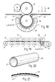
- the delivery (or printing) of the resin -1- to the sheet -2- is effected by rotogravure (Fig. 17) by means of cylinder -3-, and the engraving and polymerising of the resin is carried out at the same time by using an engraving cylinder -4-, -4'- or -4"- not having any joints, a bank -Ba- of ultraviolet ray emitters being used as the polymeriser. With -Ba'- are indicated respective banks also of ultraviolet ray emitters for obtaining a prepolymerisation in the resin.
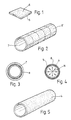
- the engraving cylinder -4- is formed by an integral metal piece not having any joints, and is obtained from a square plaquette -5- of reduced dimensions having on one of its surfaces the engraving information -6-; said engraving information being transferred from said plaquette to a cylinder -7- of plastics material, such as methacrylate, said transfer being carried out by means of a thermal repeating machine and with pressure thus providing the outer surface of said cylinder with an engraving information -6'- that is a multiple of the engraving information provided on plaquette -5-.
- This plate -10- is wound thus forming a cylinder -10'- trying to conceal as much as possible the longitudinal seam or joint -11- of the latter, and in such a way as to have the engraving information -6'- on its inner surface.
- the engraving cylinder -4'- is obtained by electroforming, for such a purpose introducing said cylinder -10'- into a vessel -R- with the corresponding bath -B- and coaxially arranging inside said cylinder a grid-walled reservoir -D- into which the nickel -N- is introduced, the cylinder -10'- and said reservoir being connected to the corresponding electrodes -E- and -E'-, thus achieving the formation of the engraving cylinder -4'- on the inner surface of cylinder -10'-, said engraving cylinder showing a slight longitudinal line -11'- which will be almost unperceivable and corresponds to the reproduction of joint -11- of cylinder -10'-.
- cylinder -10'- with the engraving information -6'- on its inner surface it is also possible to obtain by molding an integral engraving cylinder -4''- made of silicone (Fig. 11) that can be opaque or transparent, by arranging concentrically to cylinder -10'- a coaxial cylinder -12- and pressure stuffing the silicone between both said cylinders after previously having extracted by vacuum the air possibly comprised in its mass.
- a quartz engraving cylinder can be obtained by molding.
- Cylinder -10'- with the engraving information can also be obtained by joining the juxtaposed plates -5- by means of laser welding thereby forming plate -10a- whose joints -13- are barely noticeable since they are reduced to practically one tenth of a millimeter.
- the longitudinal edges of plate -10a- have a checkered profile, each length -A- corresponding to one of the component plaquettes -5- so that when forming the cylinder -10'a-the longitudinal joint -14- is still farther concealed (Fig. 15).
- the cylinder with the engraving information can be obtained, differently from the present invention, by coupling plates -5- to a magnetized carrier cylinder -15- thus obtaining cylinder -10'b-(Fig. 16).
- this plant comprises a reel -B- formed by sheet -2- made of transparent resin or plastics material (e.g., polyester) or paper guided by rolls -17- towards engraving cylinder -4-, -4'-, -4"- or -4'''- (e.g., holographic), the resin being impressed by means of flexography cylinder -3'- directly contacting upon the engraving cylinder, said sheet hence reaching this cylinder after having already been printed -2'- with the resin and before being applied against it.
- sheet -2- made of transparent resin or plastics material (e.g., polyester) or paper guided by rolls -17- towards engraving cylinder -4-, -4'-, -4"- or -4'''- (e.g., holographic)
- the resin being impressed by means of flexography cylinder -3'- directly contacting upon the engraving cylinder, said sheet hence reaching this cylinder after having already been printed -2'- with the resin and before being applied against it.
- a protecting treatment which can consist, for example, in a metalization -16- or in an application of a liquid titanium solution, after which said sheet is wound into a reel -B'- for its commercialization.
- the engraving cylinder -4-, -4'-, -4"- or -4'''- will be conveniently cooled from inside, and the ultraviolet ray emitters -18- will be placed inside a properly ventilated chamber -C-.
- the ultraviolet ray emitters can ba arranged in its inside.
- the assembly of the printing -3- or -3'-, engraving -4-, -4'-, -4"- or -4'''- and polymerising -18- means forms a compact unit -20- that will be arranged in line on a rotary machine -21- thus allowing to obtain the register of the parts engraved with optical effects as if they were the very patterns and colors to be printed on the sheet by means of the corresponding cylinder sets a, b, c, d and e comprised in the rotary machine.
- the engraving cylinder -4'''- (Fig. 20) of any material, even nonmetallic, is not formed according to the present invention, since it will have as the engraving die the peripheral coat of the own emulsion -22- provided with the corresponding engraving information and conveniently hardened.
- the printing of the resin onto the sheet is carried out by rotogravure the printing will be then effected upon the sheet as shown in Fig. 22, cylinder -3-being a rotogravure cylinder. Also in this case if the engraving cylinder is transparent the ultraviolet ray emitters can be arranged in its inside.
- Fig. 23 illustrates the incorporation of the printing-engraving-polymerising assembly -20'- (wherein the printing of the resin is effected onto sheet -2-) into a flexographic printer -21'- printing eight colors a', b', c', d', e', f', g' and h' around its central drum.
- a simplified construction of the engraving cylinder is herewith mentioned, which will be formed, differently from the present invention, by two independent halves formed by respective plates -4a- and -4b- transversally arcuate in semicircular shape.
- the engraving of sheet -2- (Fig. 17) will be obtained in two stages within the plant, whereby cylinder -15- carrying plate -4a- will act in a first stage and cylinder -15'- carrying the other plate -4b- will act in a second stage, in such a way that after the two stages the patterns corresponding to the total engraving cylinder will have been engraved.
Landscapes
- Engineering & Computer Science (AREA)
- Health & Medical Sciences (AREA)
- Physics & Mathematics (AREA)
- Mechanical Engineering (AREA)
- General Engineering & Computer Science (AREA)
- General Physics & Mathematics (AREA)
- Thermal Sciences (AREA)
- Oral & Maxillofacial Surgery (AREA)
- Computer Hardware Design (AREA)
- Microelectronics & Electronic Packaging (AREA)
- Toxicology (AREA)
- Ophthalmology & Optometry (AREA)
- Manufacturing & Machinery (AREA)
- Manufacture Or Reproduction Of Printing Formes (AREA)
- Casting Or Compression Moulding Of Plastics Or The Like (AREA)
- Shaping Of Tube Ends By Bending Or Straightening (AREA)
- Coating Apparatus (AREA)
- Sawing (AREA)
- Color Printing (AREA)
- Printing Methods (AREA)
- Agricultural Chemicals And Associated Chemicals (AREA)
- Printing Plates And Materials Therefor (AREA)
Claims (9)
- Verfahren zur Herstellung eines nahtlosen Tiefdruckzylinders zur Herstellung von Folien mit optischen Effekten, wobei man auf dem Tiefdruckzylinder (4) an dessen Außenfläche das gewünschte Muster durch Elektrogravur aufbringt, wobei man als Form die gravierte Innenfläche eines flexiblen Zylinders (8) verwendet, der durch Formung auf einem Zylinder (7) aus steifem Kunststoffmaterial erhalten und als Modell mit Gravurinformation (6') an dessen Außenoberfläche verwendet wurde, wobei der Zylinder (7) die. Gravurinformation (6) dadurch erhielt, daß man die auf einer Plakette (5) vorliegende Gravurinformation (6) mehrmals auf dem Zylinder (7) unter Anwendung von Druck und Wärme mittels einer Repetier- oder Rekombinationsmaschine reproduzierte.
- Anlage zur Herstellung von Folien mit optischen Effekten, die:und die Gravurmittel einen nach Anspruch 1 erhaltenen nahtlosen Tiefdruckzylinder (4) einschliessen.Druckmittel zur Aufbringung einer Schicht aus lichtdurchlässigem Harz auf einer Folie (2) sowie Gravurmittel zur Kontaktgravur verschiedener Muster und/oder Illustrationen auf der genannten Harzschicht sowie Polymerisationsmittel zur Polymerisation der bedruckten Harzschicht zur Erzielung der genannten optischen Effekte aufweist, wobei die Gravier- und Polymerisationsmittel gleichzeitig wirken,
- Anlage gemäss Anspruch 2, wobei als Druckmittel Rotationstiefdruck, Siebdruck, Rotationssiebdruck, Flexodruck oder Offsetdruck verwendet werden.
- Anlage gemäss Anspruch 2, wobei als Druckmittel ein Flexodruckzylinder (3') verwendet wird, der den Tiefdruckzylinder (4) direkt berührt, so daß die Schicht aus lichtdurchlässigem Harz auf dem Tiefdruckzylinder (4) abgewälzt wird, bevor die Folie (2) bedruckt wird.
- Anlage nach Anspruch 2, wobei als Druckmittel u.a. ein Rotations-Tiefdruckzylinder (3) verwendet wird, so daß die Schicht aus lichtdurchlässigem Harz auf der Folie (2) abgewälzt wird, bevor der Tiefdruckzylinder (4) berührt wird.
- Anlage nach Anspruch 2, wobei die Druck-, Gravur- und Polymerisationsmittel einen kompakten Zusammenbau (20) bilden, der auf einer Rotationsmaschine (21) in einer Reihe angeordnet ist, die weitere Druckmittel zum Bedrucken der Folie mit weiteren Motiven und Farben (a, b , c, d und e) aufweist, wobei der Zusammenbau (20) zum passergenauen Bedrucken mit den gennanten weiteren Motiven und Farben (a, b, c, d und e) in der Lage ist.
- Anlage nach Anspruch 2, wobei die genannten Polymerisationsmittel Ultraviolettbestrahlung (18) oder einen Elektronengenerator einschliessen.
- Anlage nach Anspruch 7, wobei die Ultraviolettbestrahlung einen Filter (19) für Infrarotstrahlen einschliesst.
- Anlage nach Anspruch 7, wobei die genannten Polymerisationsmittel außerhalb des genannten Tiefdruckzylinders (4) angeordnet sind.
Applications Claiming Priority (7)
| Application Number | Priority Date | Filing Date | Title |
|---|---|---|---|
| ES9602158A ES2145658B1 (es) | 1996-10-14 | 1996-10-14 | Instalacion para la obtencion de laminas con efectos opticos. |
| ES9602158 | 1996-10-14 | ||
| ES9600215 | 1996-10-14 | ||
| ES9702038 | 1997-09-30 | ||
| ES9700203 | 1997-09-30 | ||
| ES9702038 | 1997-09-30 | ||
| PCT/ES1997/000248 WO1998016362A1 (es) | 1996-10-14 | 1997-10-13 | Instalacion para la obtencion de laminas con efectos opticos |
Publications (2)
| Publication Number | Publication Date |
|---|---|
| EP0893223A1 EP0893223A1 (de) | 1999-01-27 |
| EP0893223B1 true EP0893223B1 (de) | 2002-09-18 |
Family
ID=26154998
Family Applications (1)
| Application Number | Title | Priority Date | Filing Date |
|---|---|---|---|
| EP97942963A Expired - Lifetime EP0893223B1 (de) | 1996-10-14 | 1997-10-13 | Verfahren zum herstellen einer nahtlosen gravurwalze zur herstellung von folien mit optischen effekten, und anlage mit einer solchen gravurwalze |
Country Status (11)
| Country | Link |
|---|---|
| EP (1) | EP0893223B1 (de) |
| JP (1) | JP2837544B2 (de) |
| AT (1) | ATE224281T1 (de) |
| AU (1) | AU716294B2 (de) |
| BR (1) | BR9706829A (de) |
| CA (1) | CA2239625A1 (de) |
| CU (1) | CU22557A3 (de) |
| DE (1) | DE69715610T2 (de) |
| ES (1) | ES2185049T3 (de) |
| MX (1) | MX9804550A (de) |
| WO (1) | WO1998016362A1 (de) |
Families Citing this family (7)
| Publication number | Priority date | Publication date | Assignee | Title |
|---|---|---|---|---|
| US6524675B1 (en) | 1999-05-13 | 2003-02-25 | 3M Innovative Properties Company | Adhesive-back articles |
| WO2002007945A2 (en) * | 2000-07-24 | 2002-01-31 | Steinhoff Manufacturing (Pty) Ltd. | Die wheel and method of making same |
| AT502319B1 (de) * | 2002-04-11 | 2009-11-15 | Hueck Folien Gmbh | Substrate mit vorzugsweise transferierbaren schichten und/oder oberflächenstrukturen, verfahren zu deren herstellung und deren verwendung |
| ES2224893B1 (es) | 2004-08-04 | 2005-12-16 | Neopack, S.L. | Metodo y aparato para la obtencion de hologramas y/o efectos opticos sobre un material laminar. |
| US7887722B1 (en) | 2008-05-22 | 2011-02-15 | Inx International Ink Co. | Method for transferring holographic and other microstructure or refractive images onto a web-carried resin coating in registration with printing on the web |
| JP5623021B2 (ja) * | 2009-03-02 | 2014-11-12 | ユニ・チャーム株式会社 | 塗布装置 |
| MX363517B (es) * | 2011-06-21 | 2019-03-26 | Basf Se | Rejillas de difracción de impresión en papel y tabla. |
Family Cites Families (4)
| Publication number | Priority date | Publication date | Assignee | Title |
|---|---|---|---|---|
| US4250135A (en) * | 1979-05-17 | 1981-02-10 | Orsini Peter C | Roller for producing continuous sueded or grit type finish and method of making |
| US4840757A (en) * | 1987-05-19 | 1989-06-20 | S. D. Warren Company | Replicating process for interference patterns |
| FR2619336B1 (fr) * | 1987-08-13 | 1989-12-01 | Marechal Ets | Procede pour la production d'un cylindre de grainage a chaud de feuilles thermoplastiques |
| EP0623440B1 (de) * | 1993-03-16 | 1997-09-10 | Koninklijke Philips Electronics N.V. | Verfahren und Vorrichtung zur Herstellung eines strukturierten Reliefbildes aus vernetztem Photoresist auf einer flachen Substratoberfläche |
-
1995
- 1995-11-24 JP JP9518043A patent/JP2837544B2/ja not_active Expired - Fee Related
-
1997
- 1997-10-13 AT AT97942963T patent/ATE224281T1/de not_active IP Right Cessation
- 1997-10-13 AU AU44607/97A patent/AU716294B2/en not_active Ceased
- 1997-10-13 CA CA002239625A patent/CA2239625A1/en not_active Abandoned
- 1997-10-13 EP EP97942963A patent/EP0893223B1/de not_active Expired - Lifetime
- 1997-10-13 ES ES97942963T patent/ES2185049T3/es not_active Expired - Lifetime
- 1997-10-13 WO PCT/ES1997/000248 patent/WO1998016362A1/es not_active Ceased
- 1997-10-13 DE DE69715610T patent/DE69715610T2/de not_active Expired - Fee Related
- 1997-10-13 BR BR9706829A patent/BR9706829A/pt not_active Application Discontinuation
-
1998
- 1998-06-08 CU CU1998069A patent/CU22557A3/es unknown
- 1998-06-08 MX MX9804550A patent/MX9804550A/es unknown
Also Published As
| Publication number | Publication date |
|---|---|
| WO1998016362A1 (es) | 1998-04-23 |
| JP2000502288A (ja) | 2000-02-29 |
| BR9706829A (pt) | 1999-03-23 |
| AU4460797A (en) | 1998-05-11 |
| AU716294B2 (en) | 2000-02-24 |
| DE69715610T2 (de) | 2003-08-07 |
| ATE224281T1 (de) | 2002-10-15 |
| CU22557A3 (es) | 1999-05-03 |
| MX9804550A (es) | 1998-09-30 |
| JP2837544B2 (ja) | 1998-12-16 |
| DE69715610D1 (de) | 2002-10-24 |
| ES2185049T3 (es) | 2003-04-16 |
| EP0893223A1 (de) | 1999-01-27 |
| CA2239625A1 (en) | 1998-04-23 |
Similar Documents
| Publication | Publication Date | Title |
|---|---|---|
| US4906315A (en) | Surface relief holograms and holographic hot-stamping foils, and method of fabricating same | |
| US4758296A (en) | Method of fabricating surface relief holograms | |
| US4840757A (en) | Replicating process for interference patterns | |
| JP4870568B2 (ja) | 回折格子を使用するセキュリティ印刷 | |
| EP0338378B1 (de) | Kombiniertes Druckverfahren und Verfahren zur Erzeugung von Hologrammen | |
| CA2155850A1 (en) | Process printing material and device for reproducing holographic fine structures and other diffraction grids on print products | |
| CN101434155B (zh) | 一种在板材上制作纹路图形的方法 | |
| JPH02134229A (ja) | 画像転写工具 | |
| JP2001113894A (ja) | 織物状凹凸模様を有する化粧材 | |
| JPH08300798A (ja) | 図案や標示の製作方法およびその装置 | |
| EP0893223A1 (de) | Anlage zum herstellen von folien mit optischen e-effekten | |
| JPS60169887A (ja) | ホログラム画像再生用転写シ−ト及び物品表面にホログラム画像を再生する方法 | |
| JP2004358925A (ja) | 表面装飾用転写シート、物品の表面装飾方法および装飾物品 | |
| JPS612182A (ja) | ホログラム画像再生用転写シ−ト及び物品表面にホログラム画像を再生する方法 | |
| JP3083380B2 (ja) | 熱硬化性樹脂化粧板の製造方法 | |
| JP2789599B2 (ja) | ホログラム面付型の作製方法 | |
| JPS6129529A (ja) | 熱可塑性シートの表面に連続的にエンボス加工するためのエンボスロールの製造方法 | |
| KR20240067518A (ko) | 엠보싱 마스터롤러를 이용하여 홀로그램과 제품의 식별표지가 일체형으로 마련되는 연속 홀로그램 복제필름의 제작방법 | |
| GB2215863A (en) | Continuously replicating relief holograms. | |
| RU2131615C1 (ru) | Способ одновременного изготовления реплик и прямой аппликации микроструктуры и устройство для его осуществления | |
| JPH0470340A (ja) | オフセット印刷機、および型付き印刷シートの製造方法 | |
| JPH08508106A (ja) | 印刷物上にホログラフィ微細構造及び他の回析格子を複製するための方法及びその装置 | |
| CN110757963A (zh) | 一种pof热缩膜uv镭射定位图像印刷机 | |
| JPH05498A (ja) | 微細凹凸を有する多層シートおよびその製法 | |
| JPS5887047A (ja) | 化粧合板の製法 |
Legal Events
| Date | Code | Title | Description |
|---|---|---|---|
| PUAI | Public reference made under article 153(3) epc to a published international application that has entered the european phase |
Free format text: ORIGINAL CODE: 0009012 |
|
| 17P | Request for examination filed |
Effective date: 19980709 |
|
| AK | Designated contracting states |
Kind code of ref document: A1 Designated state(s): AT BE CH DE DK ES FI FR GB GR IE IT LI LU MC NL PT SE |
|
| 17Q | First examination report despatched |
Effective date: 20000111 |
|
| RTI1 | Title (correction) |
Free format text: A METHOD FOR OBTAINING A SEAMLESS ENGRAVING CYLINDER FOR PRODUCING SHEETS WITH OPTICAL EFFECTS, AND A PLANT INCLUDING SAID CYLINDER |
|
| GRAG | Despatch of communication of intention to grant |
Free format text: ORIGINAL CODE: EPIDOS AGRA |
|
| GRAG | Despatch of communication of intention to grant |
Free format text: ORIGINAL CODE: EPIDOS AGRA |
|
| GRAH | Despatch of communication of intention to grant a patent |
Free format text: ORIGINAL CODE: EPIDOS IGRA |
|
| GRAH | Despatch of communication of intention to grant a patent |
Free format text: ORIGINAL CODE: EPIDOS IGRA |
|
| GRAA | (expected) grant |
Free format text: ORIGINAL CODE: 0009210 |
|
| AK | Designated contracting states |
Kind code of ref document: B1 Designated state(s): AT BE CH DE DK ES FI FR GB GR IE IT LI LU MC NL PT SE |
|
| PG25 | Lapsed in a contracting state [announced via postgrant information from national office to epo] |
Ref country code: NL Free format text: LAPSE BECAUSE OF FAILURE TO SUBMIT A TRANSLATION OF THE DESCRIPTION OR TO PAY THE FEE WITHIN THE PRESCRIBED TIME-LIMIT Effective date: 20020918 Ref country code: LI Free format text: LAPSE BECAUSE OF FAILURE TO SUBMIT A TRANSLATION OF THE DESCRIPTION OR TO PAY THE FEE WITHIN THE PRESCRIBED TIME-LIMIT Effective date: 20020918 Ref country code: IT Free format text: LAPSE BECAUSE OF FAILURE TO SUBMIT A TRANSLATION OF THE DESCRIPTION OR TO PAY THE FEE WITHIN THE PRESCRIBED TIME-LIMIT;WARNING: LAPSES OF ITALIAN PATENTS WITH EFFECTIVE DATE BEFORE 2007 MAY HAVE OCCURRED AT ANY TIME BEFORE 2007. THE CORRECT EFFECTIVE DATE MAY BE DIFFERENT FROM THE ONE RECORDED. Effective date: 20020918 Ref country code: GR Free format text: LAPSE BECAUSE OF FAILURE TO SUBMIT A TRANSLATION OF THE DESCRIPTION OR TO PAY THE FEE WITHIN THE PRESCRIBED TIME-LIMIT Effective date: 20020918 Ref country code: FR Free format text: LAPSE BECAUSE OF FAILURE TO SUBMIT A TRANSLATION OF THE DESCRIPTION OR TO PAY THE FEE WITHIN THE PRESCRIBED TIME-LIMIT Effective date: 20020918 Ref country code: FI Free format text: LAPSE BECAUSE OF FAILURE TO SUBMIT A TRANSLATION OF THE DESCRIPTION OR TO PAY THE FEE WITHIN THE PRESCRIBED TIME-LIMIT Effective date: 20020918 Ref country code: CH Free format text: LAPSE BECAUSE OF FAILURE TO SUBMIT A TRANSLATION OF THE DESCRIPTION OR TO PAY THE FEE WITHIN THE PRESCRIBED TIME-LIMIT Effective date: 20020918 Ref country code: BE Free format text: LAPSE BECAUSE OF FAILURE TO SUBMIT A TRANSLATION OF THE DESCRIPTION OR TO PAY THE FEE WITHIN THE PRESCRIBED TIME-LIMIT Effective date: 20020918 |
|
| REF | Corresponds to: |
Ref document number: 224281 Country of ref document: AT Date of ref document: 20021015 Kind code of ref document: T |
|
| REG | Reference to a national code |
Ref country code: GB Ref legal event code: FG4D |
|
| REG | Reference to a national code |
Ref country code: CH Ref legal event code: EP |
|
| PG25 | Lapsed in a contracting state [announced via postgrant information from national office to epo] |
Ref country code: LU Free format text: LAPSE BECAUSE OF NON-PAYMENT OF DUE FEES Effective date: 20021013 |
|
| PG25 | Lapsed in a contracting state [announced via postgrant information from national office to epo] |
Ref country code: IE Free format text: LAPSE BECAUSE OF NON-PAYMENT OF DUE FEES Effective date: 20021014 |
|
| REG | Reference to a national code |
Ref country code: IE Ref legal event code: FG4D |
|
| REF | Corresponds to: |
Ref document number: 69715610 Country of ref document: DE Date of ref document: 20021024 |
|
| PG25 | Lapsed in a contracting state [announced via postgrant information from national office to epo] |
Ref country code: SE Free format text: LAPSE BECAUSE OF FAILURE TO SUBMIT A TRANSLATION OF THE DESCRIPTION OR TO PAY THE FEE WITHIN THE PRESCRIBED TIME-LIMIT Effective date: 20021218 Ref country code: DK Free format text: LAPSE BECAUSE OF FAILURE TO SUBMIT A TRANSLATION OF THE DESCRIPTION OR TO PAY THE FEE WITHIN THE PRESCRIBED TIME-LIMIT Effective date: 20021218 |
|
| PG25 | Lapsed in a contracting state [announced via postgrant information from national office to epo] |
Ref country code: PT Free format text: LAPSE BECAUSE OF FAILURE TO SUBMIT A TRANSLATION OF THE DESCRIPTION OR TO PAY THE FEE WITHIN THE PRESCRIBED TIME-LIMIT Effective date: 20021219 |
|
| NLV1 | Nl: lapsed or annulled due to failure to fulfill the requirements of art. 29p and 29m of the patents act | ||
| REG | Reference to a national code |
Ref country code: CH Ref legal event code: PL |
|
| REG | Reference to a national code |
Ref country code: ES Ref legal event code: FG2A Ref document number: 2185049 Country of ref document: ES Kind code of ref document: T3 |
|
| PG25 | Lapsed in a contracting state [announced via postgrant information from national office to epo] |
Ref country code: MC Free format text: LAPSE BECAUSE OF NON-PAYMENT OF DUE FEES Effective date: 20030501 |
|
| EN | Fr: translation not filed | ||
| PLBE | No opposition filed within time limit |
Free format text: ORIGINAL CODE: 0009261 |
|
| STAA | Information on the status of an ep patent application or granted ep patent |
Free format text: STATUS: NO OPPOSITION FILED WITHIN TIME LIMIT |
|
| REG | Reference to a national code |
Ref country code: IE Ref legal event code: MM4A |
|
| 26N | No opposition filed |
Effective date: 20030619 |
|
| PGFP | Annual fee paid to national office [announced via postgrant information from national office to epo] |
Ref country code: ES Payment date: 20031031 Year of fee payment: 7 Ref country code: AT Payment date: 20031031 Year of fee payment: 7 |
|
| PGFP | Annual fee paid to national office [announced via postgrant information from national office to epo] |
Ref country code: GB Payment date: 20031105 Year of fee payment: 7 |
|
| PGFP | Annual fee paid to national office [announced via postgrant information from national office to epo] |
Ref country code: DE Payment date: 20031124 Year of fee payment: 7 |
|
| PG25 | Lapsed in a contracting state [announced via postgrant information from national office to epo] |
Ref country code: GB Free format text: LAPSE BECAUSE OF NON-PAYMENT OF DUE FEES Effective date: 20041013 Ref country code: AT Free format text: LAPSE BECAUSE OF NON-PAYMENT OF DUE FEES Effective date: 20041013 |
|
| PG25 | Lapsed in a contracting state [announced via postgrant information from national office to epo] |
Ref country code: ES Free format text: LAPSE BECAUSE OF NON-PAYMENT OF DUE FEES Effective date: 20041014 |
|
| PG25 | Lapsed in a contracting state [announced via postgrant information from national office to epo] |
Ref country code: DE Free format text: LAPSE BECAUSE OF NON-PAYMENT OF DUE FEES Effective date: 20050503 |
|
| GBPC | Gb: european patent ceased through non-payment of renewal fee |
Effective date: 20041013 |
|
| REG | Reference to a national code |
Ref country code: ES Ref legal event code: FD2A Effective date: 20041014 |