EP0893228B1 - Objet moulé en résine thermoplastique renforcée de fibres - Google Patents
Objet moulé en résine thermoplastique renforcée de fibres Download PDFInfo
- Publication number
- EP0893228B1 EP0893228B1 EP98113367A EP98113367A EP0893228B1 EP 0893228 B1 EP0893228 B1 EP 0893228B1 EP 98113367 A EP98113367 A EP 98113367A EP 98113367 A EP98113367 A EP 98113367A EP 0893228 B1 EP0893228 B1 EP 0893228B1
- Authority
- EP
- European Patent Office
- Prior art keywords
- reinforcing fibers
- thermoplastic material
- molded article
- fiber
- hopper
- Prior art date
- Legal status (The legal status is an assumption and is not a legal conclusion. Google has not performed a legal analysis and makes no representation as to the accuracy of the status listed.)
- Revoked
Links
Images


Classifications
-
- B—PERFORMING OPERATIONS; TRANSPORTING
- B29—WORKING OF PLASTICS; WORKING OF SUBSTANCES IN A PLASTIC STATE IN GENERAL
- B29B—PREPARATION OR PRETREATMENT OF THE MATERIAL TO BE SHAPED; MAKING GRANULES OR PREFORMS; RECOVERY OF PLASTICS OR OTHER CONSTITUENTS OF WASTE MATERIAL CONTAINING PLASTICS
- B29B7/00—Mixing; Kneading
- B29B7/80—Component parts, details or accessories; Auxiliary operations
- B29B7/88—Adding charges, i.e. additives
- B29B7/90—Fillers or reinforcements, e.g. fibres
- B29B7/905—Fillers or reinforcements, e.g. fibres with means for pretreatment of the charges or fibres
-
- B—PERFORMING OPERATIONS; TRANSPORTING
- B29—WORKING OF PLASTICS; WORKING OF SUBSTANCES IN A PLASTIC STATE IN GENERAL
- B29B—PREPARATION OR PRETREATMENT OF THE MATERIAL TO BE SHAPED; MAKING GRANULES OR PREFORMS; RECOVERY OF PLASTICS OR OTHER CONSTITUENTS OF WASTE MATERIAL CONTAINING PLASTICS
- B29B7/00—Mixing; Kneading
- B29B7/30—Mixing; Kneading continuous, with mechanical mixing or kneading devices
- B29B7/34—Mixing; Kneading continuous, with mechanical mixing or kneading devices with movable mixing or kneading devices
- B29B7/38—Mixing; Kneading continuous, with mechanical mixing or kneading devices with movable mixing or kneading devices rotary
- B29B7/40—Mixing; Kneading continuous, with mechanical mixing or kneading devices with movable mixing or kneading devices rotary with single shaft
- B29B7/42—Mixing; Kneading continuous, with mechanical mixing or kneading devices with movable mixing or kneading devices rotary with single shaft with screw or helix
- B29B7/421—Mixing; Kneading continuous, with mechanical mixing or kneading devices with movable mixing or kneading devices rotary with single shaft with screw or helix with screw and additionally other mixing elements on the same shaft, e.g. paddles, discs, bearings, rotor blades of the Banbury type
-
- B—PERFORMING OPERATIONS; TRANSPORTING
- B29—WORKING OF PLASTICS; WORKING OF SUBSTANCES IN A PLASTIC STATE IN GENERAL
- B29B—PREPARATION OR PRETREATMENT OF THE MATERIAL TO BE SHAPED; MAKING GRANULES OR PREFORMS; RECOVERY OF PLASTICS OR OTHER CONSTITUENTS OF WASTE MATERIAL CONTAINING PLASTICS
- B29B7/00—Mixing; Kneading
- B29B7/30—Mixing; Kneading continuous, with mechanical mixing or kneading devices
- B29B7/58—Component parts, details or accessories; Auxiliary operations
- B29B7/60—Component parts, details or accessories; Auxiliary operations for feeding, e.g. end guides for the incoming material
-
- B—PERFORMING OPERATIONS; TRANSPORTING
- B29—WORKING OF PLASTICS; WORKING OF SUBSTANCES IN A PLASTIC STATE IN GENERAL
- B29B—PREPARATION OR PRETREATMENT OF THE MATERIAL TO BE SHAPED; MAKING GRANULES OR PREFORMS; RECOVERY OF PLASTICS OR OTHER CONSTITUENTS OF WASTE MATERIAL CONTAINING PLASTICS
- B29B7/00—Mixing; Kneading
- B29B7/30—Mixing; Kneading continuous, with mechanical mixing or kneading devices
- B29B7/58—Component parts, details or accessories; Auxiliary operations
- B29B7/60—Component parts, details or accessories; Auxiliary operations for feeding, e.g. end guides for the incoming material
- B29B7/603—Component parts, details or accessories; Auxiliary operations for feeding, e.g. end guides for the incoming material in measured doses, e.g. proportioning of several materials
-
- B—PERFORMING OPERATIONS; TRANSPORTING
- B29—WORKING OF PLASTICS; WORKING OF SUBSTANCES IN A PLASTIC STATE IN GENERAL
- B29C—SHAPING OR JOINING OF PLASTICS; SHAPING OF MATERIAL IN A PLASTIC STATE, NOT OTHERWISE PROVIDED FOR; AFTER-TREATMENT OF THE SHAPED PRODUCTS, e.g. REPAIRING
- B29C45/00—Injection moulding, i.e. forcing the required volume of moulding material through a nozzle into a closed mould; Apparatus therefor
- B29C45/0005—Injection moulding, i.e. forcing the required volume of moulding material through a nozzle into a closed mould; Apparatus therefor using fibre reinforcements
-
- B—PERFORMING OPERATIONS; TRANSPORTING
- B29—WORKING OF PLASTICS; WORKING OF SUBSTANCES IN A PLASTIC STATE IN GENERAL
- B29C—SHAPING OR JOINING OF PLASTICS; SHAPING OF MATERIAL IN A PLASTIC STATE, NOT OTHERWISE PROVIDED FOR; AFTER-TREATMENT OF THE SHAPED PRODUCTS, e.g. REPAIRING
- B29C45/00—Injection moulding, i.e. forcing the required volume of moulding material through a nozzle into a closed mould; Apparatus therefor
- B29C45/17—Component parts, details or accessories; Auxiliary operations
- B29C45/18—Feeding the material into the injection moulding apparatus, i.e. feeding the non-plastified material into the injection unit
- B29C45/1816—Feeding auxiliary material, e.g. colouring material
-
- B—PERFORMING OPERATIONS; TRANSPORTING
- B29—WORKING OF PLASTICS; WORKING OF SUBSTANCES IN A PLASTIC STATE IN GENERAL
- B29C—SHAPING OR JOINING OF PLASTICS; SHAPING OF MATERIAL IN A PLASTIC STATE, NOT OTHERWISE PROVIDED FOR; AFTER-TREATMENT OF THE SHAPED PRODUCTS, e.g. REPAIRING
- B29C48/00—Extrusion moulding, i.e. expressing the moulding material through a die or nozzle which imparts the desired form; Apparatus therefor
- B29C48/03—Extrusion moulding, i.e. expressing the moulding material through a die or nozzle which imparts the desired form; Apparatus therefor characterised by the shape of the extruded material at extrusion
- B29C48/04—Particle-shaped
-
- B—PERFORMING OPERATIONS; TRANSPORTING
- B29—WORKING OF PLASTICS; WORKING OF SUBSTANCES IN A PLASTIC STATE IN GENERAL
- B29C—SHAPING OR JOINING OF PLASTICS; SHAPING OF MATERIAL IN A PLASTIC STATE, NOT OTHERWISE PROVIDED FOR; AFTER-TREATMENT OF THE SHAPED PRODUCTS, e.g. REPAIRING
- B29C48/00—Extrusion moulding, i.e. expressing the moulding material through a die or nozzle which imparts the desired form; Apparatus therefor
- B29C48/25—Component parts, details or accessories; Auxiliary operations
- B29C48/285—Feeding the extrusion material to the extruder
- B29C48/288—Feeding the extrusion material to the extruder in solid form, e.g. powder or granules
-
- B—PERFORMING OPERATIONS; TRANSPORTING
- B29—WORKING OF PLASTICS; WORKING OF SUBSTANCES IN A PLASTIC STATE IN GENERAL
- B29C—SHAPING OR JOINING OF PLASTICS; SHAPING OF MATERIAL IN A PLASTIC STATE, NOT OTHERWISE PROVIDED FOR; AFTER-TREATMENT OF THE SHAPED PRODUCTS, e.g. REPAIRING
- B29C48/00—Extrusion moulding, i.e. expressing the moulding material through a die or nozzle which imparts the desired form; Apparatus therefor
- B29C48/25—Component parts, details or accessories; Auxiliary operations
- B29C48/285—Feeding the extrusion material to the extruder
- B29C48/288—Feeding the extrusion material to the extruder in solid form, e.g. powder or granules
- B29C48/2886—Feeding the extrusion material to the extruder in solid form, e.g. powder or granules of fillers or of fibrous materials, e.g. short-fibre reinforcements
-
- B—PERFORMING OPERATIONS; TRANSPORTING
- B29—WORKING OF PLASTICS; WORKING OF SUBSTANCES IN A PLASTIC STATE IN GENERAL
- B29K—INDEXING SCHEME ASSOCIATED WITH SUBCLASSES B29B, B29C OR B29D, RELATING TO MOULDING MATERIALS OR TO MATERIALS FOR MOULDS, REINFORCEMENTS, FILLERS OR PREFORMED PARTS, e.g. INSERTS
- B29K2105/00—Condition, form or state of moulded material or of the material to be shaped
- B29K2105/06—Condition, form or state of moulded material or of the material to be shaped containing reinforcements, fillers or inserts
-
- B—PERFORMING OPERATIONS; TRANSPORTING
- B29—WORKING OF PLASTICS; WORKING OF SUBSTANCES IN A PLASTIC STATE IN GENERAL
- B29K—INDEXING SCHEME ASSOCIATED WITH SUBCLASSES B29B, B29C OR B29D, RELATING TO MOULDING MATERIALS OR TO MATERIALS FOR MOULDS, REINFORCEMENTS, FILLERS OR PREFORMED PARTS, e.g. INSERTS
- B29K2105/00—Condition, form or state of moulded material or of the material to be shaped
- B29K2105/06—Condition, form or state of moulded material or of the material to be shaped containing reinforcements, fillers or inserts
- B29K2105/16—Fillers
-
- B—PERFORMING OPERATIONS; TRANSPORTING
- B29—WORKING OF PLASTICS; WORKING OF SUBSTANCES IN A PLASTIC STATE IN GENERAL
- B29K—INDEXING SCHEME ASSOCIATED WITH SUBCLASSES B29B, B29C OR B29D, RELATING TO MOULDING MATERIALS OR TO MATERIALS FOR MOULDS, REINFORCEMENTS, FILLERS OR PREFORMED PARTS, e.g. INSERTS
- B29K2707/00—Use of elements other than metals for preformed parts, e.g. for inserts
- B29K2707/04—Carbon
-
- B—PERFORMING OPERATIONS; TRANSPORTING
- B29—WORKING OF PLASTICS; WORKING OF SUBSTANCES IN A PLASTIC STATE IN GENERAL
- B29K—INDEXING SCHEME ASSOCIATED WITH SUBCLASSES B29B, B29C OR B29D, RELATING TO MOULDING MATERIALS OR TO MATERIALS FOR MOULDS, REINFORCEMENTS, FILLERS OR PREFORMED PARTS, e.g. INSERTS
- B29K2709/00—Use of inorganic materials not provided for in groups B29K2703/00 - B29K2707/00, for preformed parts, e.g. for inserts
- B29K2709/02—Ceramics
-
- B—PERFORMING OPERATIONS; TRANSPORTING
- B29—WORKING OF PLASTICS; WORKING OF SUBSTANCES IN A PLASTIC STATE IN GENERAL
- B29K—INDEXING SCHEME ASSOCIATED WITH SUBCLASSES B29B, B29C OR B29D, RELATING TO MOULDING MATERIALS OR TO MATERIALS FOR MOULDS, REINFORCEMENTS, FILLERS OR PREFORMED PARTS, e.g. INSERTS
- B29K2709/00—Use of inorganic materials not provided for in groups B29K2703/00 - B29K2707/00, for preformed parts, e.g. for inserts
- B29K2709/08—Glass
Definitions
- the present invention relates to a molded article made of fiber-reinforced thermoplastic material.
- thermoplastic resin reinforced with fibers such as glass fibers
- process for producing the molded article made of the fiber-reinforced thermoplastic resin comprising the steps of: melt-kneading the thermoplastic resin with reinforcing fibers in an extruder to produce pellets of the fiber-reinforced thermoplastic resin in which the reinforcing fibers are contained in the thermoplastic resin; feeding the pellets into an injector to melt and knead the same again to produce kneaded material; and supplying the kneaded material into a mold to form the same into a predetermined form.
- thermoplastic resin As a process for preparing the pellets of the fiber-reinforced thermoplastic resin by way of melt-kneading the thermoplastic resin with the reinforcing fibers, there has been known a process comprising the steps of: providing an extruder having a first opening for receiving the thermoplastic resin and a second opening, which is provided in the down flow area from the first opening, for receiving the reinforcing fibers; feeding the thermoplastic resin into the extruder through the first opening to plasticize the same in a melting zone of the extruder; adding the reinforcing fibers to the thermoplastic resin, which has reached the second opening, through the second opening; kneading the plasticized thermoplastic resin and the reinforcing fibers in a portion of the extruder between the second opening and the outlet of the extruder; and pelletizing the kneaded material.
- a problem with this method is that a large device of complex structure is required to be used because the extruder has the opening for receiving the thermoplastic resin and the opening for receiving the reinforcing fibers, separately.
- the aforementioned method in which the previously produced pellets of the fiber-reinforced thermoplastic resin are again melted and kneaded in the extruder, is problematic in that the use of the kneaded material produced by the method usually results in a molded article made of the fiber-reinforced thermoplastic resin which contains fibers of extremely short length and has undesirable physical properties because kneading of the materials is carried out in the extruder and the injector, separately, twice in total.
- JP-A-2-153714 discloses a method comprising the steps of: providing an injector having a first opening for receiving the thermoplastic resin and a second opening, which is provided at a down flow area from the first opening, for receiving the reinforcing fibers; feeding the thermoplastic resin through the first opening into the injector to melt the same in a melting zone of the injector; feeding the reinforcing fibers into the injector through the second opening; kneading the molten thermoplastic resin and the reinforcing fibers in the injector; and supplying the kneaded material directly into the mold to form the same.
- JP-A-6-8278 discloses a method comprising the steps of: providing an injector which is provided with a single opening for receiving raw materials; feeding both the reinforcing fibers and the thermoplastic resin simultaneously into the injector through the opening; kneading the materials in the injector; and supplying the kneaded materials directly into the mold to form the same.
- the molded article made of the fiber-reinforced thermoplastic resin obtained by the above method is not always satisfactory in its physical properties such as an impact strength, because the molded article merely contains reinforcing fibers having a length of 400-500 ⁇ m at most.
- US-A-3 577 494 relates to a method for the preparation of extrudable synthetic resinous materials. Improved feed of granular synthetic resinous material in screw extruders is obtained and fiber breakage is significantly reduced when chopped glass fiber and extrudable resin are mixed in an extruder having an increasing working volume screw. The product has significantly improved impact strength.
- the object of the present invention is to provide a molded article made of fiber-reinforced thermoplastic material wherein the molded article is excellent in physical properties such as impact strength.
- One embodiment of the aspect may be a molded article made of the fiber-reinforced thermoplastic material which contains the reinforcing fibers having a ratio of a weight average length to a number average length of 1.1 or more.
- Another embodiment of the aspect may be a molded article made of the fiber-reinforced thermoplastic material wherein the content of the reinforcing fibers falls within the range of from about 20% by weight to about 75% by weight.
- Still another embodiment of the aspect may be a molded article made of the fiber-reinforced thermoplastic material which contains the reinforcing fibers having a diameter from about 6 ⁇ m to about 25 ⁇ m.
- the molded article made of the fiber-reinforced thermoplastic material will be referred to as a "fiber-reinforced molded article”.
- thermoplastic material applied to the present invention may be thermoplastic materials which are applicable to conventional molding methods such as injection molding, injection compression molding, extrusion molding and stamping molding.
- thermoplastic materials include thermoplastic resins such as polyolefins, e.g., polyethylene and polypropylene, polystyrene, polycarbonate, acrylonitrile-styrene-butadiene block copolymer; thermoplastic elastomers such as ethylene-propylene block copolymer and styrene-butadiene block copolymer; and thermoplastic polymer alloys.
- the thermoplastic material may contain additives, which can normally be used in processing thermoplastic materials, such as a filler, e.g., talc; a pigment; an antistatic agent; and an antioxidant.
- a filler e.g., talc
- a pigment e.g., talc
- an antistatic agent e.g., talc
- an antioxidant e.g., talc
- the reinforcing fibers applied to the present invention are not restricted as long as they are able to reinforce the thermoplastic material, and may be fibers which have been used for reinforcement of thermoplastic materials, such as glass fibers, carbon fibers, alumina fibers and aramid fibers.
- a weight average length of the reinforcing fibers contained in the fiber-reinforced molded article of the present invention is about 2 mm or more, preferably from about 2 mm to about 50 mm.
- the fiber-reinforced molded article containing the reinforcing fiber of such weight average length is excellent in physical properties such as impact strength.
- the weight average length of the reinforcing fibers contained in the fiber-reinforced molded article can be determined by the following procedure. A piece cut from the fiber-reinforced molded article is burned with direct fire to remove the thermoplastic material. About 130 to 150 fibers are arbitrarily gathered to be measured both weight and length of each fiber.
- a content of the reinforcing fibers in the fiber-reinforced molded article is not particularly limited, but it preferably falls within the range of from about 20% by weight to about 75% by weight from the viewpoint of physical properties of the fiber-reinforced molded article.
- the fiber-reinforced molded article preferably contains the reinforcing fibers with a diameter of from about 6 ⁇ m to about 25 ⁇ m.
- the fiber-reinforced molded article of the present invention can be produced by a process comprising the following steps of:
- thermoplastic material in the solid state is not particularly limited in size and shape as long as it can be fed into the plasticizing apparatus and kneaded.
- Thermoplastic material in a form of pellets, granules or powders may be normally used in the present invention.
- the reinforcing fibers to be fed into the plasticizing apparatus are not particularly limited in form as long as they are from about 3 mm to about 50 mm long.
- Chopped strands which are produced by cutting a roved strand (a continuing strand) containing several hundreds or several thousands of monofilaments having a diameter of from about 6 ⁇ m to about 25 ⁇ m bundled with a binder into about 3 mm to about 50 mm length, is preferably employed.
- the present invention may use either chopped strands which have been previously cut into a predetermined length and stored or chopped strands which have cut into the predetermined length with a roving cutter provided near the material-feed opening of the plasticizing apparatus, directly.
- the roved strands are preferably treated with a surface sizing agent in order to enhance bonding strength of its surface with the thermoplastic material.
- the kind of the surface sizing agent may be chosen depending mainly upon the kind of the thermoplastic material used.
- Modified thermoplastic material which can be bonded to the reinforcing fibers is preferably used in order to attain a firm bond between the thermoplastic material and the reinforcing fibers. It also is preferable that a modifier for making the thermoplastic material capable of bonding with the reinforcing fibers is fed into the plasticizing apparatus with the thermoplastic material and the reinforcing fibers. For example, in cases where polypropylene and glass fibers are used, respectively, as the thermoplastic material and the reinforcing fibers, polypropylene modified with maleic acid is preferably used as the polypropylene. It also is preferable that unmodified polypropylene, glass fibers and maleic acid as a modifier are fed into the plasticizing apparatus together.
- the modifier is often used in a form of pellets, it may be used in a form of granules or powders in order to attain its good dispersion into the thermoplastic material.
- the modifier is dry-blended with the thermoplastic material in the solid state, and then the resulting mixture is fed into the plasticizing apparatus together with the reinforcing fibers, followed by carrying out the steps of melting and kneading in the plasticizing apparatus.
- a modifier with a relatively small particle size is preferably used so as to attain a desirable effect of the modifier even kneading weakly.
- the use of thermoplastic material in which the modifier has previously compounded is also preferred.
- the amount of the modifier compounded varies depending upon e.g. amount and kind of the reinforcing fibers and kind of the thermoplastic material, but it is normally falls within the range of from about 1% by weight to about 15% by weight based on the weight of the thermoplastic material.
- a fiber-reinforced molded article produced by using the above-mentioned raw materials it is preferred that almost every strand is loosened into monofilaments which uniformly disperse in the thermoplastic material, and that the molded article has few voids. Unloosened strands and voids may cause deterioration of the physical properties of the fiber-reinforced molded article.
- the fiber-reinforced molded article of the present invention can be produced by the method comprising the following steps of :
- Fig. 1 shows one example of a molding machine usable for producing the fiber-reinforced molded article of the present invention.
- the molding machine includes a plasticizing apparatus (B), a molding apparatus (C) and an apparatus (A) for feeding raw materials into the plasticizing apparatus (B).
- the raw material-feeding apparatus (A) illustrated in Fig. 1 has a roving cutter (1) for discharging the reinforcing fibers with a predetermined length, a quantitative feeder (2) for discharging the thermoplastic material in the solid state, and a hopper (4) for introducing the reinforcing fibers from the roving cutter (1) and the thermoplastic material from the feeder (2) into the plasticizing apparatus (B).
- the plasticizing apparatus (B) may be a screw-type injector (3) having the material-feed opening which opens with facing the hopper.
- the plasticizing apparatus may be either another type of injector or an extruder.
- the molding apparatus (C) may comprise a mold (8) and a press device (7) having a clamping mechanism.
- the quantitative feeder for discharging the chopped strands which have been previously cut into the predetermined length may be employed in place of the roving cutter (1).
- the quantitative feeder (2) for discharging the thermoplastic material may be replaced with another device which can discharge the thermoplastic material quantitatively.
- the reinforcing fibers from the roving cutter (1) and the thermoplastic material from the quantitative feeder (2) are introduced by the hopper (4) and fed into the injector (3) simultaneously through the common material-feed opening.
- an inner pipe (5) is provided over the hopper (4).
- the reinforcing fibers cut into the predetermined length by the roving cutter (1) are fed inside the inner pipe (5).
- the quantitative feeder (2) is equipped with a shoot (6).
- the thermoplastic material discharged from the quantitative feeder (2) naturally flows down on the shoot (6) to be fed into a space lying between an inner wall of the hopper (4) and an outer wall of the inner pipe(5).
- the injector (3) has the material-feed opening which opens with facing the hopper.
- the reinforcing fibers, which are introduced by the hopper, are fed into the injector through the material-feed opening.
- An tip end of the injector (3) is connected with the mold (8).
- the kneaded material produced in the injector (3) can be injected into the cavity through a passage (9) provided in the mold (8).
- the roving cutter (1) has, as schematically shown in Fig. 2, a first feeding roll (111) and a second feeding roll (112) for sending out roved fibers (L) with spreading them, and a cutting roll (12) provided on the exit side of the feeding rolls and having a width wider than the spreading width of the roved fibers (L) spread by the feeding rolls.
- the cutting roll (12) has at least one cutting blade which can contact with the second feeding roll (112) when rotating.
- the roved fibers (L) is cut by the cutting blade and the second feeding roll (112) into a predetermined length and drop forward the inner pipe (5).
- the cutting roll (12) is provided so that the cut reinforcing fibers (L1) fall inside the inner pipe (5).
- a length of the cut reinforcing fiber (L1) may be determined depending upon a pitch of the cutting blade(s) provided on the cutting roll (12). The pitch is set so that the reinforcing fibers are cut into about 3-50 mm, preferably about 3-25 mm.
- six roved glass fibers of 2400 tex are sent into a nip defined by a first feeding roll (111) and a second feeding roll (112) to be cut into 14 mm length.
- the cut reinforcing fibers (L1) are discharged from the roving cutter at a speed of 2.2 kg per minute.
- the yarn number and the number of the roved fibers to be sent to the roving cutter and the discharging speed of the cut reinforcing fibers from the roving cutter may be suitably changed.
- polypropylene was used as the thermoplastic material, and roving glass fibers whose surface had been treated with modified polypropylene was employed in order to enhance the adhesiveness between polypropylene and the reinforcing fibers.
- the quantitative feeder (2) has, as schematically shown in Fig. 3, a hopper (21) for accumulating the thermoplastic material in the solid state, and a conveyer (22) for conveying the thermoplastic material supplied from the hopper (21).
- the discharging speed of the thermoplastic material from the quantitative feeder (2) can be controlled by adjusting the rotating speed of a motor for driving the conveyer (22).
- the thermoplastic material discharged from the quantitative feeder (22) slips down on the shoot which is connected with the quantitative feeder and are fed into a space lying between the inner wall of the hopper (4) and the outer wall of the inner pipe (5).
- the modifier and other additives may be supplied to the quantitative feeder together with the thermoplastic material.
- the thermoplastic material, the modifier and the additives may be dry-blended, followed by being supplied to the quantitative feeder.
- pellets of polypropylene resin commercial name: Sumitomo Noblen AX568; manufactured by Sumitomo Chemical Co., Ltd.
- a modifier with a particle diameter of 1.5 mm or less commercial name: Umex; manufactured by Sanyo Chemical Industries, Ltd.
- the hopper (4) is a member for allowing both the reinforcing fibers (L1), which were cut into the predetermined length and discharged by the roving cutter (1), and the thermoplastic material discharged from the quantitative feeder (2) to be contacted and mixed with each other and to be introduced toward the material-feed opening of the injector (3).
- the hopper (4) may be made of any materials, it is preferred that the hopper is made of a material which is difficult to generate static electricity even if it collides or contacts with the reinforcing fibers and the thermoplastic material.
- the hopper (4) may be equipped with a vibrator (43) so that the reinforcing fibers do not attach to the hopper. Air may be blown on a part of the hopper (4) where the reinforcing fibers tend to attach because of static electricity.
- the hopper (4) is preferably equipped with means for controlling the amount of the accumulated reinforcing fibers and thermoplastic material.
- an upper switch (41) for detecting an upper limit of an upper surface of the accumulated materials, and a lower switch (42) for detecting an lower limit of the upper surface of the accumulated materials are provided to the hopper (4).
- This example employed a hopper made of stainless steel coated with a polyethylene terephthalate film having a thickness of 0.4 mm, as the hopper (4).
- the hopper (4) was equipped with the upper switch (41) and the lower switch (42) with an interval of 150 mm.
- the hopper (4) had a oval section in a horizontal direction and an angle between its inner wall and the vertical line of 10°.
- the inner pipe (5) provided in the hopper (4) leads the reinforcing fibers (L1) dropping from the cutting roll (12) to the vicinity of the center of the hopper (4).
- the inner pipe (5) may be made of any materials, it is preferred that it is made of a material which is difficult to generate static electricity even if it collides with the reinforcing fibers and the thermoplastic material.
- Diameters of an upper opening (51) and an lower opening (52) of the inner pipe (5) may be either equal to or different from each other.
- the upper opening means an entrance of the inner pipe for receiving the reinforcing fibers (L1).
- the lower opening is an exit of the inner pipe for discharging the reinforcing fibers.
- the diameter of the lower opening (52), normally, is shorter than that of the upper opening (51).
- An angle ( ⁇ ') between the inner wall of the inner pipe (5) and a vertical line is 30° or less, preferably 15° or less. Vibrating the inner pipe (5) has an effect on preventing the reinforcing fibers from attaching to the inner wall of the inner pipe (5) resulting in clogging the inner pipe (5).
- the inner pipe (5) may be vibrated by a vibrator. Alternatively, when the pellets of the thermoplastic material are supplied into the hopper (4), the inner pipe (5) may be vibrated by the collision of the pellets with the outer wall of the inner pipe.
- This example used, as the inner pipe (5), a pipe made of stainless steel whose inner surface was coated with a polyethylene terephthalate film with a thickness of 0.4 mm. Diameters of the upper opening (51) and the lower opening (52) were 65 mm each. The pellets of the thermoplastic material was fed into the hopper (4) so as to collide with the outer wall of the inner pipe (5) to vibrate the same.
- the screw type injector (3) is, as illustrated in Fig. 4, provided with an opening for receiving the reinforcing fibers and the thermoplastic material in the solid state.
- the opening is referred to as a "material-feed opening”.
- the screw (31)of the injector (3) preferably requires that a part of the screw positioning under the material-feed opening satisfies the following inequality (3): ⁇ (p/2) 2 ⁇ - (q/2) 2 ⁇ r ⁇ 350 in order to prevent the reinforcing fibers from breaking to maintain the reinforcing fibers in the kneaded material relatively long while kneading the thermoplastic material and the reinforcing fibers in the injector.
- p, q and r respectively, indicate an inner diameter (cm) of a barrel, a diameter (cm) of the screw at its groove bottom, and a flight pitch (cm) of the screw.
- the value of the smallest part between the flights is selected as the value of q.
- the diameter of the material-feed opening is normally set equal to a diameter of the barrel, the flight pitch of the screw, r, in the inequality (3) is replaced with the diameter of the material-feed opening when the diameter of this opening is smaller than r.
- the screw retracts with its rotation, and therefore, a part of the screw which positions under the material-feed opening changes with the rotation of the screw.
- the inequality (3) is preferably satisfied for all parts of the screw which may come under the material-feed opening.
- the diameter of the material-feed opening was 12 cm
- p was 12
- q was 8.7
- r was 10.8.
- the value of the left side of the inequality (3) was 579.
- the screw (31) preferably is a full flight screw.
- a mixing head having a check ring mechanism is preferably provided to the tip portion of the screw. This example employed a full flight screw equipped with the mixing head (32) to its tip end.
- the screw (3) can be sectioned, from its rear end to its tip end, into three zones including a feed zone (311), a compression zone (312) and a metering zone (313).
- a groove depth of the feed zone (311) was set to 16.5 mm and a groove depth of the metering zone (313) was set to 5.25 mm.
- a groove depth of the compression zone (312) was tapered from 16.5 mm to 5.25 mm.
- the ratio among the lengths of the feed zone (311), the compression zone (312) and the metering zone (313) was set to 2:1:1.
- the flight pitch of the screw (31) in its full flight portion was set to 120 mm, which was equal to the diameter of the screw.
- a compression ratio of the screw (31) preferably is 4 or less.
- An apparent shear rate preferably is 10 sec -1 or less.
- the compression ratio and the apparent shear rate are given by the following equations (4) and (5), respectively.
- Compression ratio (groove depth in feed zone) / (groove depth of metering zone)
- Apparent shear rate ( ⁇ ⁇ D ⁇ n) / (60 ⁇ H) D, n and H indicate the diameter (mm) of the screw (31), the screw speed (r.p.m.) and the groove depth (mm), respectively.
- the screw can be rotated and moved reciprocatorily in its axial direction by a screw driving device (33).
- the compression rate of the screw was 3.14.
- the apparent shear rate of the screw was 71.8 sec -1 when the screw was rotated at the screw speed of 60 r.p.m.
- the above-mentioned raw material-feeding apparatus (A) and the plasticizing apparatus (B) work, for example, under a control by a computer according to the flow-chart shown in Fig. 5.
- a process for producing the fiber-reinforced molded article of the present invention using the molding machine having the raw material-feeding apparatus (A), the plasticizing apparatus (B) and the molding apparatus will be described below.
- the work of the molding machine is commenced by starting the roving cutter (1) and the quantitative feeder (2).
- the pellets of the thermoplastic material are fed, together with the modifier previously dry-blended, into the hopper (21) of the quantitative feeder (2) and supplied, in order, onto the conveyer (2).
- the pellets of the thermoplastic material are conveyed by the conveyer (2) to the shoot (6).
- the pellets slip on the shoot to be fed into the hopper (4).
- the reinforcing fibers cut by the roving cutter (1) is fed into the hopper (4) via the inner pipe (5).
- the pellets of the thermoplastic material and the reinforcing fibers are accumulated in the hopper (4).
- the kneaded material is injected from the injector (3) to be supplied into the cavity (X) through the passage (9) provided in the mold (8).
- the kneaded material supplied into the cavity is formed to the predetermined shape in the cavity. After cooling in an adequate degree, the fiber-reinforced molded article is taken out from the mold.
- the reinforcing fibers and the pellets of the thermoplastic material were quantitatively fed into the hopper (4).
- a large portion of the reinforcing fibers is located near the center of the hopper with being surrounded by a large portion of the pellets of the thermoplastic material. Consequently, since there are few reinforcing fibers near the inner wall of the hopper (4), the time taken to uniformly disperse the reinforcing fibers into the thermoplastic material became constant and the content of the reinforcing fibers in the fiber-reinforced molded article also became constant.
- This example used glass fibers and polypropylene resin, respectively, as the reinforcing fibers and the thermoplastic material.
- the glass fibers with a length of 14 mm were fed into the hopper (4) in a rate of 2.2 kg/min from the roving cutter (1) via the inner pipe (5).
- the pellets of the polypropylene resin were fed into the hopper (4) in a rate of 5.1 kg/min with being collided with the outer wall of the inner pipe (5). It took eighteen seconds from the start of rotating the screw to the completion of producing 2.2 kg of kneaded material containing both the glass fibers and the polypropylene resin. The time from the start of rotating the screw to the completion of producing the kneaded material is called the plasticizing time.
- the kneaded material is called plasticized fiber-reinforced polypropylene resin.
- the weight of the glass fiber-reinforced molded article and the plasticizing time were approximately constant for each repeated molding cycle.
- the glass fibers and the pellets of the polypropylene resin were smoothly fed into the hopper (4) without clogging the hopper (4).
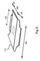
- Fig. 6 illustrates the perspective view of the fiber-reinforced molded article obtained in the example.
- Bending test according to JIS K 7203 and Izod impact test according to JIS K 7110 were carried out for test specimens cut from the center portion of the molded article.
- the weight average length and the number average length of the reinforcing fibers contained in the fiber-reinforced molded article were obtained using the test specimens.
- the content of the glass fibers was 31.0% by weight.
- Example 1 The above example is indicated as Example 1.
- the test results are shown in Table 1.
- Example 2 the glass fiber-reinforced polypropylene resin molded article was produced according to the same manner as described in Example 1, except for cutting the glass fibers into 6 mm length by the roving cutter (1).
- the bending test and Izod impact test were carried out and the weight average length and the number average length were obtained in a manner similar to that of Example 1.
- the content of the glass fibers was 30.5% by weight.
- the test results are shown in Table 1. Test result Example 1
- Example 2 L w (mm) 4.2 2.6 L m (mm) 3.4 2.3 L w / L m 1.24 1.13 Bending modulus of elasticity (GPa) 4.84 5.15 Bending strength (MPa) 115.1 121.1 Izod impact strength (kg) 21.9 15.3
- the fiber-reinforcing molded article made of the thermoplastic material of the present invention is extremely superior in physical properties such as impact strength, because it contains the reinforcing fibers with a length of about 3 mm to about 50 mm.
Landscapes
- Engineering & Computer Science (AREA)
- Mechanical Engineering (AREA)
- Manufacturing & Machinery (AREA)
- Reinforced Plastic Materials (AREA)
- Processing And Handling Of Plastics And Other Materials For Molding In General (AREA)
- Injection Moulding Of Plastics Or The Like (AREA)
Claims (3)
- Article moulé en matière thermoplastique renforcée par des fibres caractérisé en ce que
l'article moulé contient des fibres renforçantes (L1) d'une longueur moyenne en masse (Lw ) d'environ 2 mm ou plus, et
les fibres renforçantes (L1) contenues dans l'article moulé ont un rapport d'une longueur moyenne en masse (Lw ) à une longueur moyenne en nombre (Ln ) de 1,1 ou plus, où
Lw = Σ(Li x Wi )/ΣWi et Ln = Σ(Li x Ni )/ΣNi où Li est une longueur (mm), Wi est une masse (g) et Ni est un nombre des fibres renforçantes. - Article moulé renforcé par des fibres selon la revendication 1 où la teneur des fibres renforçantes (L1) dans l'article moulé est située dans la gamme d'environ 20 % en masse à environ 75 % en masse.
- Article moulé renforcé par des fibres selon la revendication 1 ou 2 où les fibres renforcantes (L1) contenues dans l'article moulé ont un diamètre d'environ 6 µm à environ 25 µm.
Priority Applications (1)
| Application Number | Priority Date | Filing Date | Title |
|---|---|---|---|
| EP02016912A EP1260347A3 (fr) | 1997-07-15 | 1998-07-13 | Procédé pour la fabrication d'un objet moulé en résine thermoplastique renforcée de fibres |
Applications Claiming Priority (3)
| Application Number | Priority Date | Filing Date | Title |
|---|---|---|---|
| JP189504/97 | 1997-07-15 | ||
| JP18950497 | 1997-07-15 | ||
| JP9189504A JPH1135701A (ja) | 1997-07-15 | 1997-07-15 | 繊維強化熱可塑性樹脂成形品 |
Related Child Applications (1)
| Application Number | Title | Priority Date | Filing Date |
|---|---|---|---|
| EP02016912A Division EP1260347A3 (fr) | 1997-07-15 | 1998-07-13 | Procédé pour la fabrication d'un objet moulé en résine thermoplastique renforcée de fibres |
Publications (2)
| Publication Number | Publication Date |
|---|---|
| EP0893228A1 EP0893228A1 (fr) | 1999-01-27 |
| EP0893228B1 true EP0893228B1 (fr) | 2004-06-30 |
Family
ID=16242386
Family Applications (2)
| Application Number | Title | Priority Date | Filing Date |
|---|---|---|---|
| EP02016912A Withdrawn EP1260347A3 (fr) | 1997-07-15 | 1998-07-13 | Procédé pour la fabrication d'un objet moulé en résine thermoplastique renforcée de fibres |
| EP98113367A Revoked EP0893228B1 (fr) | 1997-07-15 | 1998-07-13 | Objet moulé en résine thermoplastique renforcée de fibres |
Family Applications Before (1)
| Application Number | Title | Priority Date | Filing Date |
|---|---|---|---|
| EP02016912A Withdrawn EP1260347A3 (fr) | 1997-07-15 | 1998-07-13 | Procédé pour la fabrication d'un objet moulé en résine thermoplastique renforcée de fibres |
Country Status (5)
| Country | Link |
|---|---|
| US (1) | US6159408A (fr) |
| EP (2) | EP1260347A3 (fr) |
| JP (1) | JPH1135701A (fr) |
| KR (1) | KR19990013726A (fr) |
| DE (1) | DE69824793T2 (fr) |
Cited By (1)
| Publication number | Priority date | Publication date | Assignee | Title |
|---|---|---|---|---|
| CN105459288A (zh) * | 2014-09-25 | 2016-04-06 | 丰田自动车株式会社 | 制造纤维增强树脂模制品的制造方法 |
Families Citing this family (14)
| Publication number | Priority date | Publication date | Assignee | Title |
|---|---|---|---|---|
| JP3767511B2 (ja) | 2001-04-26 | 2006-04-19 | 東洋紡績株式会社 | 熱収縮性ポリエステル系フィルムロール |
| US7026377B1 (en) | 2001-08-31 | 2006-04-11 | Mayco Plastics | High performance fiber reinforced thermoplastic resin, method and apparatus for making the same |
| DE10152246A1 (de) * | 2001-10-23 | 2003-05-08 | Krauss Maffei Kunststofftech | Kunststoffverarbeitende Maschine zum Herstellen von faserbeladenen thermoplastischen Kunststoffprodukten |
| DE102005000683A1 (de) * | 2004-08-21 | 2006-03-09 | Saertex Wagener Gmbh & Co. Kg | Verfahren zur Herstellung eines Faserverbundwerkstoffes zur Herstellung von Faserverbundbauteilen |
| US20060103045A1 (en) * | 2004-11-17 | 2006-05-18 | O'brien-Bernini Frank C | Wet use chopped strand glass as reinforcement in extruded products |
| US7601282B2 (en) * | 2005-10-24 | 2009-10-13 | Johns Manville | Processes for forming a fiber-reinforced product |
| DE102012212610A1 (de) * | 2012-07-18 | 2014-01-23 | Bayerische Motoren Werke Aktiengesellschaft | Verfahren zur Herstellung von Leichtbauelementen aus kohlenstofffaserverstärktem, thermoplastischem Kunststoff |
| US11541581B2 (en) | 2016-09-02 | 2023-01-03 | Zurn Industries, Llc | Injection molded cold-expansion compression collar |
| US11543065B2 (en) | 2016-09-02 | 2023-01-03 | Zurn Industries, Llc | Extruded cold-expansion compression collar |
| CA2977581A1 (fr) | 2016-09-02 | 2018-03-02 | Zurn Industries, Llc | Collier de compression a dilatation a froid moule par injection |
| US11054076B2 (en) | 2016-11-04 | 2021-07-06 | Zurn Industries, Llc | Reinforcing ring with sleeve |
| JP6884480B2 (ja) | 2017-09-21 | 2021-06-09 | 株式会社日本製鋼所 | 繊維強化熱可塑性樹脂からなる成形品の成形方法および成形装置 |
| WO2021167937A1 (fr) * | 2020-02-17 | 2021-08-26 | Halkey-Roberts Corporation | Trémie pour machine de moulage par injection |
| JP2022109612A (ja) * | 2021-01-15 | 2022-07-28 | 株式会社日本製鋼所 | 射出成形装置および射出成形方法 |
Family Cites Families (18)
| Publication number | Priority date | Publication date | Assignee | Title |
|---|---|---|---|---|
| GB946059A (en) * | 1961-05-19 | 1964-01-08 | Du Pont | Fiber-containing shaped articles |
| FR1530229A (fr) * | 1966-07-15 | 1968-06-21 | Dow Chemical Co | Procédé et appareil destinés à l'incorporation d'une matière filamenteuses dansune matrice résineuse |
| GB1159230A (en) * | 1967-08-25 | 1969-07-23 | Gen Motors Corp | Method of making Fibre-Reinforced Synthetic Resin Articles |
| US3577494A (en) * | 1969-09-05 | 1971-05-04 | Dow Chemical Co | Method for the preparation of extrudable synthetic resinous materials |
| US3644271A (en) * | 1970-03-02 | 1972-02-22 | Ethyl Corp | Composition and process for injection molding thermoplastic material and glass fibers |
| US3732345A (en) * | 1970-04-16 | 1973-05-08 | Dow Chemical Co | Method for the incorporation of filamentary material in a resinous matrix |
| GB1439327A (en) * | 1972-06-28 | 1976-06-16 | Nat Res Dev | Pelletised fibres |
| US4169186A (en) * | 1978-04-17 | 1979-09-25 | Asahi-Dow Limited | Molding material structure |
| US5213889B1 (en) * | 1981-01-21 | 1996-10-29 | Kawasaki Chem Holding | Fibre-reinforced compositions and methods for producing such compositions |
| US4559262A (en) * | 1981-01-21 | 1985-12-17 | Imperial Chemical Industries, Plc | Fibre reinforced compositions and methods for producing such compositions |
| US4408694A (en) * | 1981-05-28 | 1983-10-11 | Owens-Illinois, Inc. | Reinforced plastic home canning ring |
| US4549920A (en) * | 1981-07-28 | 1985-10-29 | Imperial Chemical Industries, Plc | Method for impregnating filaments with thermoplastic |
| DE3315707A1 (de) * | 1983-04-29 | 1984-10-31 | Bayer Ag, 5090 Leverkusen | Formteil aus kunststoff mit verstaerkten einlagen |
| DE69021361T2 (de) * | 1989-08-21 | 1996-02-29 | Sumitomo Chemical Co., Ltd., Osaka | Verfahren zur herstellung eines faserverstärkten thermoplastkunststoffgiesserzeugnisses. |
| US5538784A (en) * | 1992-03-25 | 1996-07-23 | E. I. Du Pont De Nemours And Company | Process for molding fiber-reinforced thermoplastic polymer articles |
| DE9311731U1 (de) * | 1993-08-06 | 1993-10-14 | Hoechst Ag, 65929 Frankfurt | Spritzgußformteil aus Thermoplastwerkstoff |
| US5653534A (en) * | 1994-10-12 | 1997-08-05 | Sumitomo Chemical Company, Limited | Screw apparatus and method for supplying reinforcing fiber-containing molten resin using the apparatus |
| DE19548854C2 (de) * | 1995-12-27 | 1997-10-02 | Ebers & Mueller Fibrit | Verfahren zur Herstellung von Gegenständen aus faserverstärkten Thermoplasten |
-
1997
- 1997-07-15 JP JP9189504A patent/JPH1135701A/ja active Pending
-
1998
- 1998-07-09 KR KR1019980027611A patent/KR19990013726A/ko not_active Ceased
- 1998-07-13 EP EP02016912A patent/EP1260347A3/fr not_active Withdrawn
- 1998-07-13 DE DE69824793T patent/DE69824793T2/de not_active Revoked
- 1998-07-13 US US09/114,224 patent/US6159408A/en not_active Expired - Fee Related
- 1998-07-13 EP EP98113367A patent/EP0893228B1/fr not_active Revoked
Cited By (2)
| Publication number | Priority date | Publication date | Assignee | Title |
|---|---|---|---|---|
| CN105459288A (zh) * | 2014-09-25 | 2016-04-06 | 丰田自动车株式会社 | 制造纤维增强树脂模制品的制造方法 |
| CN105459288B (zh) * | 2014-09-25 | 2019-03-22 | 丰田自动车株式会社 | 制造纤维增强树脂模制品的制造方法 |
Also Published As
| Publication number | Publication date |
|---|---|
| EP0893228A1 (fr) | 1999-01-27 |
| US6159408A (en) | 2000-12-12 |
| EP1260347A2 (fr) | 2002-11-27 |
| EP1260347A3 (fr) | 2004-03-03 |
| KR19990013726A (ko) | 1999-02-25 |
| DE69824793T2 (de) | 2005-06-30 |
| DE69824793D1 (de) | 2004-08-05 |
| JPH1135701A (ja) | 1999-02-09 |
Similar Documents
| Publication | Publication Date | Title |
|---|---|---|
| US6419864B1 (en) | Method of preparing filled, modified and fiber reinforced thermoplastics and twin screw extruder for putting the method into practice | |
| US6159408A (en) | Molded article made of fiber-reinforced thermoplastic material and process for producing the same | |
| EP0706873B1 (fr) | Appareil à mélanger et méthode d'utilisation de cet appareil pour distribuer de la résine fondue comprenant des fibres | |
| US5358680A (en) | Process for manufacturing a composite product by moulding | |
| US5165941A (en) | Extruder apparatus and process for compounding thermoplastic resin and fibres | |
| JP3755293B2 (ja) | 繊維強化熱可塑性樹脂の可塑化装置用スクリュおよび可塑化装置 | |
| US5185117A (en) | Process for compounding thermoplastic resin and fibers | |
| CA2024337C (fr) | Extrudeuse et procede pour l'integration d'une resine thermoplastique et de fibres | |
| JP3280875B2 (ja) | 可塑化装置 | |
| KR100927521B1 (ko) | 용융된 폴리머를 압출하는 장치 | |
| KR20200042934A (ko) | 섬유 강화 열가소성 수지의 혼련 방법, 가소화 장치 및 압출기 | |
| EA004153B1 (ru) | Способ изготовления формованных изделий и установка для его осуществления | |
| JP3786981B2 (ja) | 繊維強化熱可塑性樹脂混練用フルフライトスクリュー及びスクリュー式射出機 | |
| HU216514B (hu) | Eljárás tárgyak, különösen alakos testek szálerősítésű, hőre lágyuló műanyagokból való előállítására | |
| JP7125604B2 (ja) | 強化樹脂成形体の製造装置及び製造方法 | |
| JP6621149B2 (ja) | コンクリート型枠用せき板の押出成形方法及びコンクリート型枠用せき板の押出成形装置 | |
| JPH09150436A (ja) | 射出方法及びこの方法を実施する射出装置 | |
| JP3509238B2 (ja) | 溶融樹脂への強化繊維混入方法及びこれを実施する装置 | |
| JP3236234B2 (ja) | 可塑化装置 | |
| JP3280874B2 (ja) | 繊維と熱可塑性樹脂材料の可塑化装置への供給方法および可塑化装置 | |
| JP2023546261A (ja) | 長繊維の熱可塑性材料加工のための方法およびシングルスクリュー押し出しシステム | |
| JP2009051170A (ja) | 繊維強化熱可塑性樹脂組成物の製造装置およびその製造方法 | |
| JP2005144834A (ja) | 繊維強化合成樹脂製品と繊維強化合成樹脂粒の製造方法及び装置 | |
| JPH11138601A (ja) | 長繊維強化熱可塑性樹脂成形体の製造方法 | |
| JP2022109612A (ja) | 射出成形装置および射出成形方法 |
Legal Events
| Date | Code | Title | Description |
|---|---|---|---|
| PUAI | Public reference made under article 153(3) epc to a published international application that has entered the european phase |
Free format text: ORIGINAL CODE: 0009012 |
|
| AK | Designated contracting states |
Kind code of ref document: A1 Designated state(s): DE FR GB IT |
|
| AX | Request for extension of the european patent |
Free format text: AL;LT;LV;MK;RO;SI |
|
| 17P | Request for examination filed |
Effective date: 19990714 |
|
| AKX | Designation fees paid |
Free format text: DE FR GB IT |
|
| 17Q | First examination report despatched |
Effective date: 20010731 |
|
| GRAP | Despatch of communication of intention to grant a patent |
Free format text: ORIGINAL CODE: EPIDOSNIGR1 |
|
| RIC1 | Information provided on ipc code assigned before grant |
Ipc: 7B 29K 101:12 Z Ipc: 7B 29C 70/12 B Ipc: 7B 29C 47/10 A |
|
| RTI1 | Title (correction) |
Free format text: MOLDED ARTICLE MADE OF FIBER-REINFORCED THERMOPLASTIC MATERIAL |
|
| GRAS | Grant fee paid |
Free format text: ORIGINAL CODE: EPIDOSNIGR3 |
|
| GRAA | (expected) grant |
Free format text: ORIGINAL CODE: 0009210 |
|
| AK | Designated contracting states |
Kind code of ref document: B1 Designated state(s): DE FR GB IT |
|
| REG | Reference to a national code |
Ref country code: GB Ref legal event code: FG4D |
|
| REF | Corresponds to: |
Ref document number: 69824793 Country of ref document: DE Date of ref document: 20040805 Kind code of ref document: P |
|
| PLBI | Opposition filed |
Free format text: ORIGINAL CODE: 0009260 |
|
| 26 | Opposition filed |
Opponent name: QUADRANT PLASTIC COMPOSITES AG Effective date: 20040828 |
|
| RAP2 | Party data changed (patent owner data changed or rights of a patent transferred) |
Owner name: SUMITOMO CHEMICAL COMPANY, LIMITED |
|
| ET | Fr: translation filed | ||
| PLAX | Notice of opposition and request to file observation + time limit sent |
Free format text: ORIGINAL CODE: EPIDOSNOBS2 |
|
| PLAF | Information modified related to communication of a notice of opposition and request to file observations + time limit |
Free format text: ORIGINAL CODE: EPIDOSCOBS2 |
|
| PGFP | Annual fee paid to national office [announced via postgrant information from national office to epo] |
Ref country code: DE Payment date: 20060706 Year of fee payment: 9 |
|
| PGFP | Annual fee paid to national office [announced via postgrant information from national office to epo] |
Ref country code: GB Payment date: 20060712 Year of fee payment: 9 |
|
| PGFP | Annual fee paid to national office [announced via postgrant information from national office to epo] |
Ref country code: FR Payment date: 20060719 Year of fee payment: 9 |
|
| PGFP | Annual fee paid to national office [announced via postgrant information from national office to epo] |
Ref country code: IT Payment date: 20060731 Year of fee payment: 9 |
|
| RDAF | Communication despatched that patent is revoked |
Free format text: ORIGINAL CODE: EPIDOSNREV1 |
|
| RDAG | Patent revoked |
Free format text: ORIGINAL CODE: 0009271 |
|
| STAA | Information on the status of an ep patent application or granted ep patent |
Free format text: STATUS: PATENT REVOKED |
|
| 27W | Patent revoked |
Effective date: 20061022 |
|
| GBPR | Gb: patent revoked under art. 102 of the ep convention designating the uk as contracting state |
Free format text: 20061022 |