EP0893258A2 - Dispositif et procédé d'impression numérique à jet d'encre - Google Patents
Dispositif et procédé d'impression numérique à jet d'encre Download PDFInfo
- Publication number
- EP0893258A2 EP0893258A2 EP98202341A EP98202341A EP0893258A2 EP 0893258 A2 EP0893258 A2 EP 0893258A2 EP 98202341 A EP98202341 A EP 98202341A EP 98202341 A EP98202341 A EP 98202341A EP 0893258 A2 EP0893258 A2 EP 0893258A2
- Authority
- EP
- European Patent Office
- Prior art keywords
- waveform
- nozzle
- providing
- pulses
- look
- Prior art date
- Legal status (The legal status is an assumption and is not a legal conclusion. Google has not performed a legal analysis and makes no representation as to the accuracy of the status listed.)
- Withdrawn
Links
- 238000000034 method Methods 0.000 title claims abstract description 30
- 238000007641 inkjet printing Methods 0.000 title claims abstract description 8
- 230000003287 optical effect Effects 0.000 claims abstract description 32
- 230000004044 response Effects 0.000 claims abstract description 11
- 238000007639 printing Methods 0.000 claims description 20
- 238000013139 quantization Methods 0.000 claims description 16
- 230000001934 delay Effects 0.000 claims 1
- 239000000976 ink Substances 0.000 description 57
- 230000008901 benefit Effects 0.000 description 8
- 238000010586 diagram Methods 0.000 description 6
- 230000006870 function Effects 0.000 description 5
- 239000011159 matrix material Substances 0.000 description 5
- 230000008569 process Effects 0.000 description 5
- 238000009792 diffusion process Methods 0.000 description 4
- 238000004519 manufacturing process Methods 0.000 description 3
- 238000002834 transmittance Methods 0.000 description 3
- 238000010521 absorption reaction Methods 0.000 description 2
- 239000007788 liquid Substances 0.000 description 2
- 230000009466 transformation Effects 0.000 description 2
- 241001270131 Agaricus moelleri Species 0.000 description 1
- 230000004913 activation Effects 0.000 description 1
- 230000015572 biosynthetic process Effects 0.000 description 1
- 230000006837 decompression Effects 0.000 description 1
- 238000007726 management method Methods 0.000 description 1
- 238000012986 modification Methods 0.000 description 1
- 230000004048 modification Effects 0.000 description 1
- 230000009467 reduction Effects 0.000 description 1
- 230000000007 visual effect Effects 0.000 description 1
Images


Classifications
-
- B—PERFORMING OPERATIONS; TRANSPORTING
- B41—PRINTING; LINING MACHINES; TYPEWRITERS; STAMPS
- B41J—TYPEWRITERS; SELECTIVE PRINTING MECHANISMS, i.e. MECHANISMS PRINTING OTHERWISE THAN FROM A FORME; CORRECTION OF TYPOGRAPHICAL ERRORS
- B41J2/00—Typewriters or selective printing mechanisms characterised by the printing or marking process for which they are designed
- B41J2/005—Typewriters or selective printing mechanisms characterised by the printing or marking process for which they are designed characterised by bringing liquid or particles selectively into contact with a printing material
- B41J2/01—Ink jet
- B41J2/015—Ink jet characterised by the jet generation process
- B41J2/04—Ink jet characterised by the jet generation process generating single droplets or particles on demand
- B41J2/045—Ink jet characterised by the jet generation process generating single droplets or particles on demand by pressure, e.g. electromechanical transducers
- B41J2/04501—Control methods or devices therefor, e.g. driver circuits, control circuits
- B41J2/04573—Timing; Delays
-
- B—PERFORMING OPERATIONS; TRANSPORTING
- B41—PRINTING; LINING MACHINES; TYPEWRITERS; STAMPS
- B41J—TYPEWRITERS; SELECTIVE PRINTING MECHANISMS, i.e. MECHANISMS PRINTING OTHERWISE THAN FROM A FORME; CORRECTION OF TYPOGRAPHICAL ERRORS
- B41J2/00—Typewriters or selective printing mechanisms characterised by the printing or marking process for which they are designed
- B41J2/005—Typewriters or selective printing mechanisms characterised by the printing or marking process for which they are designed characterised by bringing liquid or particles selectively into contact with a printing material
- B41J2/01—Ink jet
- B41J2/015—Ink jet characterised by the jet generation process
- B41J2/04—Ink jet characterised by the jet generation process generating single droplets or particles on demand
-
- B—PERFORMING OPERATIONS; TRANSPORTING
- B41—PRINTING; LINING MACHINES; TYPEWRITERS; STAMPS
- B41J—TYPEWRITERS; SELECTIVE PRINTING MECHANISMS, i.e. MECHANISMS PRINTING OTHERWISE THAN FROM A FORME; CORRECTION OF TYPOGRAPHICAL ERRORS
- B41J2/00—Typewriters or selective printing mechanisms characterised by the printing or marking process for which they are designed
- B41J2/005—Typewriters or selective printing mechanisms characterised by the printing or marking process for which they are designed characterised by bringing liquid or particles selectively into contact with a printing material
- B41J2/01—Ink jet
- B41J2/015—Ink jet characterised by the jet generation process
- B41J2/04—Ink jet characterised by the jet generation process generating single droplets or particles on demand
- B41J2/045—Ink jet characterised by the jet generation process generating single droplets or particles on demand by pressure, e.g. electromechanical transducers
- B41J2/04501—Control methods or devices therefor, e.g. driver circuits, control circuits
- B41J2/0458—Control methods or devices therefor, e.g. driver circuits, control circuits controlling heads based on heating elements forming bubbles
-
- B—PERFORMING OPERATIONS; TRANSPORTING
- B41—PRINTING; LINING MACHINES; TYPEWRITERS; STAMPS
- B41J—TYPEWRITERS; SELECTIVE PRINTING MECHANISMS, i.e. MECHANISMS PRINTING OTHERWISE THAN FROM A FORME; CORRECTION OF TYPOGRAPHICAL ERRORS
- B41J2/00—Typewriters or selective printing mechanisms characterised by the printing or marking process for which they are designed
- B41J2/005—Typewriters or selective printing mechanisms characterised by the printing or marking process for which they are designed characterised by bringing liquid or particles selectively into contact with a printing material
- B41J2/01—Ink jet
- B41J2/015—Ink jet characterised by the jet generation process
- B41J2/04—Ink jet characterised by the jet generation process generating single droplets or particles on demand
- B41J2/045—Ink jet characterised by the jet generation process generating single droplets or particles on demand by pressure, e.g. electromechanical transducers
- B41J2/04501—Control methods or devices therefor, e.g. driver circuits, control circuits
- B41J2/04588—Control methods or devices therefor, e.g. driver circuits, control circuits using a specific waveform
-
- B—PERFORMING OPERATIONS; TRANSPORTING
- B41—PRINTING; LINING MACHINES; TYPEWRITERS; STAMPS
- B41J—TYPEWRITERS; SELECTIVE PRINTING MECHANISMS, i.e. MECHANISMS PRINTING OTHERWISE THAN FROM A FORME; CORRECTION OF TYPOGRAPHICAL ERRORS
- B41J2/00—Typewriters or selective printing mechanisms characterised by the printing or marking process for which they are designed
- B41J2/005—Typewriters or selective printing mechanisms characterised by the printing or marking process for which they are designed characterised by bringing liquid or particles selectively into contact with a printing material
- B41J2/01—Ink jet
- B41J2/015—Ink jet characterised by the jet generation process
- B41J2/04—Ink jet characterised by the jet generation process generating single droplets or particles on demand
- B41J2/045—Ink jet characterised by the jet generation process generating single droplets or particles on demand by pressure, e.g. electromechanical transducers
- B41J2/04501—Control methods or devices therefor, e.g. driver circuits, control circuits
- B41J2/0459—Height of the driving signal being adjusted
-
- B—PERFORMING OPERATIONS; TRANSPORTING
- B41—PRINTING; LINING MACHINES; TYPEWRITERS; STAMPS
- B41J—TYPEWRITERS; SELECTIVE PRINTING MECHANISMS, i.e. MECHANISMS PRINTING OTHERWISE THAN FROM A FORME; CORRECTION OF TYPOGRAPHICAL ERRORS
- B41J2/00—Typewriters or selective printing mechanisms characterised by the printing or marking process for which they are designed
- B41J2/005—Typewriters or selective printing mechanisms characterised by the printing or marking process for which they are designed characterised by bringing liquid or particles selectively into contact with a printing material
- B41J2/01—Ink jet
- B41J2/015—Ink jet characterised by the jet generation process
- B41J2/04—Ink jet characterised by the jet generation process generating single droplets or particles on demand
- B41J2/045—Ink jet characterised by the jet generation process generating single droplets or particles on demand by pressure, e.g. electromechanical transducers
- B41J2/04501—Control methods or devices therefor, e.g. driver circuits, control circuits
- B41J2/04591—Width of the driving signal being adjusted
-
- B—PERFORMING OPERATIONS; TRANSPORTING
- B41—PRINTING; LINING MACHINES; TYPEWRITERS; STAMPS
- B41J—TYPEWRITERS; SELECTIVE PRINTING MECHANISMS, i.e. MECHANISMS PRINTING OTHERWISE THAN FROM A FORME; CORRECTION OF TYPOGRAPHICAL ERRORS
- B41J2/00—Typewriters or selective printing mechanisms characterised by the printing or marking process for which they are designed
- B41J2/005—Typewriters or selective printing mechanisms characterised by the printing or marking process for which they are designed characterised by bringing liquid or particles selectively into contact with a printing material
- B41J2/01—Ink jet
- B41J2/015—Ink jet characterised by the jet generation process
- B41J2/04—Ink jet characterised by the jet generation process generating single droplets or particles on demand
- B41J2/045—Ink jet characterised by the jet generation process generating single droplets or particles on demand by pressure, e.g. electromechanical transducers
- B41J2/04501—Control methods or devices therefor, e.g. driver circuits, control circuits
- B41J2/04595—Dot-size modulation by changing the number of drops per dot
-
- B—PERFORMING OPERATIONS; TRANSPORTING
- B41—PRINTING; LINING MACHINES; TYPEWRITERS; STAMPS
- B41J—TYPEWRITERS; SELECTIVE PRINTING MECHANISMS, i.e. MECHANISMS PRINTING OTHERWISE THAN FROM A FORME; CORRECTION OF TYPOGRAPHICAL ERRORS
- B41J2/00—Typewriters or selective printing mechanisms characterised by the printing or marking process for which they are designed
- B41J2/005—Typewriters or selective printing mechanisms characterised by the printing or marking process for which they are designed characterised by bringing liquid or particles selectively into contact with a printing material
- B41J2/01—Ink jet
- B41J2/21—Ink jet for multi-colour printing
- B41J2/2121—Ink jet for multi-colour printing characterised by dot size, e.g. combinations of printed dots of different diameter
- B41J2/2128—Ink jet for multi-colour printing characterised by dot size, e.g. combinations of printed dots of different diameter by means of energy modulation
-
- H—ELECTRICITY
- H04—ELECTRIC COMMUNICATION TECHNIQUE
- H04N—PICTORIAL COMMUNICATION, e.g. TELEVISION
- H04N1/00—Scanning, transmission or reproduction of documents or the like, e.g. facsimile transmission; Details thereof
- H04N1/40—Picture signal circuits
- H04N1/40025—Circuits exciting or modulating particular heads for reproducing continuous tone value scales
-
- H—ELECTRICITY
- H04—ELECTRIC COMMUNICATION TECHNIQUE
- H04N—PICTORIAL COMMUNICATION, e.g. TELEVISION
- H04N1/00—Scanning, transmission or reproduction of documents or the like, e.g. facsimile transmission; Details thereof
- H04N1/40—Picture signal circuits
- H04N1/40025—Circuits exciting or modulating particular heads for reproducing continuous tone value scales
- H04N1/40043—Circuits exciting or modulating particular heads for reproducing continuous tone value scales using more than one type of modulation, e.g. pulse width modulation and amplitude modulation
-
- H—ELECTRICITY
- H04—ELECTRIC COMMUNICATION TECHNIQUE
- H04N—PICTORIAL COMMUNICATION, e.g. TELEVISION
- H04N1/00—Scanning, transmission or reproduction of documents or the like, e.g. facsimile transmission; Details thereof
- H04N1/40—Picture signal circuits
- H04N1/40087—Multi-toning, i.e. converting a continuous-tone signal for reproduction with more than two discrete brightnesses or optical densities, e.g. dots of grey and black inks on white paper
Definitions
- the present invention generally relates to image printing apparatus and methods, and more particularly relates to a digital ink jet printing apparatus and method for variable gray scale printing on a receiver medium in such a manner that "quantization errors", visible noise, excessive ink laydown and printing time are reduced.
- An ink jet printer produces images on a receiver medium by ejecting ink droplets onto the receiver medium in an imagewise fashion.
- the advantages of non-impact, low-noise, low energy use, and low cost operation and the capability of the printer to print on plain paper are largely responsible for the wide acceptance of ink jet printers in the marketplace.
- ink jet printers only print discrete ink dots and at discrete optical density levels.
- unintended and extraneous ink dots which are most visible in low-density areas of the image on the receiver medium, give rise to undesirable image artifacts.
- an input digital image with substantially continuous or high bit-depth pixel values are typically "quantized" to the available density values in the ink jet printer apparatus.
- quantization errors occur. These quantization errors often produce image artifacts that appear to the viewer of the image as posterization or contouring.
- quantization errors can be reduced by increasing the available levels of optical densities, reduction of quantization errors increase printing time and ink laydown. Increased ink laydown on the receiver medium requires higher liquid absorption by the receiver medium, which is undesirable.
- a disadvantage of the technique disclosed in US-A-4,714,935 is the increased printing time and increased ink laydown on the receiver medium. As previously mentioned, increased ink laydown on the receiver medium requires higher liquid absorption by the receiver medium, which is undesirable.
- Another problem associated with prior art ink jet printers is image artifacts and visible noise caused by manufacturing variability among the plurality of ink jet nozzles comprising a printhead. More specifically, variability in the print head fabrication process produces variability in the nozzles (for example,, variability in the size of nozzle orifices) comprising the printhead, which in turn causes undesirable variability in ink droplet volume for droplets ejected from the nozzles. As a result, some nozzles print higher densities than other nozzles. Such variability causes visible noise or image artifacts, such as banding or streaks, along the movement direction of the print head relative to the receiver medium.
- an object of the present invention is to provide a digital ink jet printing apparatus and method for variable gray scale printing on a receiver medium in such a manner that "quantization errors", visible noise, excessive ink laydown and printing time are reduced.
- the present invention resides in an ink jet printing apparatus for printing an image on a receiver medium in response to an input image file having a plurality of pixels, each pixel described by at least one pixel value respectively associated with an optical density, comprising a printhead, at least one nozzle integrally attached to said printhead, said nozzle capable of ejecting an ink droplet associated with the optical density, a waveform generator associated with said nozzle for generating an electronic waveform to be supplied to said nozzle, so that said nozzle ejects the ink droplet in response to the waveform supplied thereto, the waveform defined by a plurality of pulses, a look-up table associated with said waveform generator for storing a plurality of waveform serial numbers assigned to respective waveforms, each waveform being defined by at least one predetermined parameter and a calibrator receiving the input image for converting the pixel values of the input image to waveform index number associated with the waveform serial number.
- a feature of the present invention is the provision of a look-up table that includes electronic waveforms with respective waveform serial numbers and corresponding to desired printed optical densities, the electronic waveforms being capable of driving the print head.
- Another feature of the present invention is the provision of a calibration unit in which each pixel of an image file is converted to waveform index numbers associated with waveform serial numbers.
- An advantage of the present invention is that quantization errors are reduced.
- Another advantage of the present invention is that visible noise caused by manufacturing variabilities among printhead nozzles is reduced.
- a further advantage of the present invention is that excessive ink laydown is reduced.
- Yet another advantage of the present invention is that printing time is reduced.
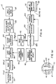
- a system block diagram generally referred to as 10, includes an electronic memory 20 having a digital image file I(x,y) stored therein.
- image file I(x,y) the letters "x" and “y” designate column and row numbers, respectively, the combination of which define pixel locations in a plane of pixels (not shown). More specifically, a plurality of color pixels with pixel values at each "x" and "y" location correspond to desired color densities (that is, "aim densities") when printed on a receiver medium 30.
- Image file I(x,y) may be generated by a computer or, alternatively, provided as an input generated from a magnetic disk, a compact disk, a memory card, a magnetic tape, a digital camera, a print scanner, a film scanner, or the like. Moreover, image file I(x,y) may be provided in any suitable format well known in the art, such as page-description language or bitmap format.
- image processor 40 electrically connected to electronic memory 20 is an image processor 40, which processes image file I(x,y) such that image processor 40 is capable of performing any one of several desired operations on image file I(x,y). These operations may be, for example, decoding, decompression, rotation, resizing, coordinate transformation, mirror-image transformation, tone scale adjustment, color management, in addition to other desired operations.
- Image processor 40 generates an output image file I p (x,y), which includes a plurality of pixel values having color code values, the pixel values corresponding to respective ink delivery nozzles 45 (only one of which is shown) in an ink jet print head 50, each nozzle 45 having an ink chamber 46 for ejecting an ink droplet 47 therefrom.
- printer performance look-up table (LUT) 60 data related to performance of apparatus 10 are stored in printer performance look-up table (LUT) 60 and a printer performance curve 100 (see Fig. 4).
- image file I p (x, y) is calibrated in an image calibrator 70 which converts color pixel values at each pixel to waveform index numbers IN, as described more fully hereinbelow.
- LUT 60 provides an electronic waveform, generally referred to as 80, comprising a group of "square" pulses, generally referred to as 90 (only three of which are shown), for driving print head 50.
- Electronic waveform 80 is characterized by the number of square pulses, pulse widths (that is, W 1 , W 2 , W 3 ...), voltage pulse amplitudes (that is, A 1 , A 2 , A 3 %), and delay time intervals (that is, S 1-2 , S 2-3 ...) between pulses 90.
- Predetermined values of pulse amplitudes, widths and delay time intervals between pulses are selected depending on a desired mode of operation of printhead 50.
- a desired mode of operation for a piezoelectric ink jet print head 50 may be that frequencies of pulses 90 are reinforced by the resonance frequencies of an ink chamber 46, which is associated with each ink nozzle 45, so that energy cost for ink ejection is minimized.
- Predetermining the values of the number of pulses, pulse amplitude, pulse width and time delay between pulses results in discrete ink droplet volumes that are modulatable by electronic waveform 80.
- square pulses 90 are only an example of many possible electronic waveforms usable for driving print head 50.
- Alternative electronic waveforms usable with the present invention include, for example, triangular, trapezoidal, and sinusoidal waveforms, either in unipolar or bi-polar voltages.
- electronic waveform 80 may be fully or partially continuous without one or more delay time intervals (S 1-2 , S 2-3 ).
- Such waveforms can be characterized by predetermined parameters in similar fashion to the example of the square wave 90.
- a continuous sinusoidal wave can be characterized by the period and the amplitude of each cycle or each half cycle plus a constant voltage offset.
- optical density refers to the reflective or the transmittance optical densities as measured by a densitometer (not shown) set in the well-known Status "A” or Status "M” mode, respectively.
- Such reflective and transmittance optical densities are measured from reflective (for example, coated paper) and transmittance (for example, transparent film) ink receivers.
- the density D i is measured from a uniform density patch of a test image, which is printed by driving the nozzles with the waveform corresponding to the waveform serial numbers SN i .
- N is the total number of electronic waveforms in LUT 60 and "D max " is the maximum achievable optical density.
- LUT 60 also includes the previously mentioned parameters, which characterize waveform 80. As previously mentioned, these parameters are the widths (W 1 , W 2 , W 3 %), the amplitudes (A 1 , A 2 , A 3 %), and the delay time intervals between pulses (S 1-2 , S 2-3 ). However, it is understood from the teachings herein that a different set of parameters will obtain for electronic waveforms other than the square waveform 80 shown in Fig. 3.
- optical densities D 1 , D 2 , D 3 ... are tabulated as a monatomic function of waveform serial number SN for a predetermined electronic waveform 80 (for example,, square wave 90).
- the series of electronic waveforms SN i listed in LUT 60 are only a subset of all possible electronic waveforms capable of driving ink jet print head 50.
- many electronic waveforms result in equal or similar optical densities D i .
- Only suitable ones of these waveforms need be selected and listed as the electronic waveforms in LUT 60.
- Such a selection is made by minimizing the gap or difference between any two optical densities D i and the corresponding two consecutive waveform serial numbers SN i . Minimizing such gaps minimize quantization errors and thereby arrive at suitable waveforms.
- printer performance curve 100 formed by plotting optical density as a function of waveform index number IN.
- the N electronic waveforms in LUT 60 are used to print an image comprising uniform-density patches (not shown) from which optical densities are obtained for each waveform serial number SN corresponding to the waveform.
- the plurality of "x" symbols in Fig. 4 represent the data points obtained from LUT 60 corresponding to the SN's in LUT 60.
- the data points "x" are interpolated by techniques well known in the art to produce a continuous curve for expressing IN as a continuous variable.
- waveform serial number SN i is a description of the discrete optical density levels (that is, tones) that the ink jet printer is capable of producing.
- the total level N ranges from 2 to 64 available levels, that is, 1 to 6 bit depth.
- the index number waveform IN represents substantially continuous tone. Of course, there should be higher than 8 bit levels (2 8 ), for example, 10 - 12 bits, used to describe the waveform index numbers IN.
- image file I p (x,y) is calibrated by image calibrator 70.
- I p (x,y) includes color pixel values for each of the yellow, magenta and cyan color planes. That is, each color code value is associated with an aim optical density for that color, as defined by the input image file I(x,y).
- the calibration performed by image calibrator 70 converts each color pixel value to a waveform index number IN using (a) the aim density at that pixel for that color and (b) printer performance curve 100 (see Fig. 4). This calibration process results in an image file IN(x,y) with pixel values described by waveform index numbers IN.
- image halftoning unit 110 is used to minimize image artifacts.
- image halftoning refers to the image processing technique which creates the appearance of intermediate tones by the spatial modulation of two tones, for example, black and white, or multiple levels of tones, such as black, white and gray levels.
- Halftoning improves image quality by minimizing image artifacts such as contouring and noise, both of which result from printing with a finite number of tone levels.
- image halftoning is often referred to as multiple level halftoning, or multi-level halftoning, or simply multitoning.
- image halftoning includes bi-level halftoning, as well.
- calibrated image file IN(x,y) is input to image halftoning unit 110.
- Calibrated image file IN(x,y) comprises a plurality of pixels with each pixel described by waveform index number IN for each color.
- the waveform index numbers IN are now effectively continuous in nature, which are described in more than 8 bit per pixel per color.
- the total number of waveform serial numbers, N corresponding to different optical densities, is in the range 2 1 to 2 6 , which is much smaller than the total number of waveform index numbers IN.
- simple quantization to the optical densities D i represented by the waveform serial numbers SN i produces visible image artifacts on the printed images.
- the function of image halftoning unit 110 is to quantify the calibrated image file IN(x,y) with pixel values described by the waveform index number IN to an image file SN(x,y) with pixel values described by the waveform serial numbers SN i . This is accomplished by spatially modulating adjacent waveform serial numbers SN i (that is, image halftoning). These waveform serial numbers SN's are stored in LUT 60.
- image halftoning unit 110 comprising a suitable halftoning error diffusion algorithm.
- any of a number of halftoning algorithms well known in the art can be used, such as multilevel ordered dither and multilevel error diffusion.
- Input image file IN(x,y) is in substantially continuous tone with pixel values described by waveform index numbers (for example,, 8 bits or higher).
- the column and row address of the input pixels are given by x and y, respectively.
- Modulo operator 120 and Modulo operator 130 are used to produce column and row indices x d and y d , respectively, which are used to address a dither matrix 140 to determine an addressed dither value d(x d , y d ).
- Dither matrix 140 comprises an array of dither values having column and row dimensions M x and M y , respectively.
- the dither values stored in the dither matrix 140 may correspond to any of many different types of dither patterns. For example, any one of well-known clustered-dot dither patterns, such as Bayer dither patterns, can be used. Several dither patterns having minimum visibility to a human observer can be used, such as those described in commonly assigned U.S.
- Patents 5,214,517 and 5,586,203 are next added to the input calibrated image file values IN(x,y) using an adder 150 to produce a plurality of modified pixel values. Each modified pixel value is then processed using a quantizer 160 to produce a multitoned pixel value SN(x,y).
- the halftoning technique disclosed hereinabove is by way of example only because many other halftoning techniques may be used.
- Fig. 6 illustrates another embodiment of image halftoning unit 110 for providing an error diffusion algorithm.
- Input image file IN(x,y) is in substantially continuous tone with pixel values described by waveform index numbers IN's (in 2 L levels).
- the calibrated image input value IN(x,y) for an input pixel is processed using a quantizer 180 to form a multitoned pixel value SN(x,y).
- a difference signal generator 190 computes the difference between the calibrated input pixel value IN(x,y) and the multitoned pixel value SN(x,y), thus representing the error introduced by the quantization process. In some cases, it may be desirable to scale either IN(x,y) or SN(x,y) before computing the difference signal provided by difference signal generator 190.
- the difference signal is next multiplied by a series of error weighting factors, W ij , using a weighted error generator 200.
- the resulting weighted difference signals are provided to an adder 210 which adds the weighted difference signals to the calibrated input values of nearby pixels that have yet to be processed to form modified calibrated input values.
- the propagation of the errors made during the quantization process to the nearby pixels ensures that the mean of the pixel values is preserved over a local image region.
- any one of a plurality of error-weight matrices W i,j can be used in weighted error generator 200 and the multilevel error diffusion algorithm disclosed hereinabove is only one example of many possible algorithms useable with the present invention.
- examples of such error-weight matrices, W ij are disclosed in "Digital Halftoning", p241, The MIT Press, Cambridge, MA, by R. Ulichney, 1987.
- controller 220 performs the function of controlling the correct waveforms to be generated for corresponding pixels. Controller 220 accomplishes this function by (a) receiving a waveform serial number SN at each pixel and each color of the halftoned image file SN(x,y); (b) looking up the waveform parameters corresponding to the waveform serial number SN at that pixel and color of SN(x,y) using the printer performance LUT 60; (c) sending the waveform parameters to waveform generator 230; and (d) selecting the correct nozzle 45 corresponding to that color and the pixel by sending signals to a nozzle selector 240 that is connected to waveform generator 230.
- Waveform generator 230 generates correct waveforms in response to the waveform parameters provided by the controller 220 for providing the proper waveforms to actuate an electromechanical transducer 250 or a heat generating element 260 that in turn ejects droplet 47 from ink nozzles 45 in print head 50.
- ink jet print head 50 may be a piezo-electric ink jet printhead as shown in Fig. 1a.
- ink jet printhead 50 may be a thermal ink jet printhead comprising a heat generating element 260 disposed in at least one nozzle 45 for generating thermal energy in response to electronic waveforms for ejecting ink droplets 47 from nozzle 45, as shown in Fig. 1b.
- the waveform generator 230 can include an electric circuit (not shown) for producing the correct digital waveforms in combination with a digital-to-analog converter (not shown), and amplifiers (also not shown). Image-wise activation and ink ejection of ink droplets 47 reproduces the input digital image on receiver 30.
- An advantage of the present invention is that noise is reduced. This is so because pixel values in the image files are converted into calibrated waveform index numbers which define electronic waveforms for controlling the print head and that the dithering or image halftoning is conducted on the calibrated image files.
- the pixel values of the output from dither matrix 140 are described as waveform serial numbers that can be used directly for controlling the ink jet print head. That is, since no additional calibration is performed after halftoning, the introduction of additional noise is avoided.
- Another advantage of the present invention is that printing time is reduced. This is so because the number of printing passes needed for each image area is reduced.
- the present invention is compatible with an ink-jet printer apparatus using inks of different densities for each color.
- the present invention can also incorporate printing modes such as printing a plurality of ink droplets at each image location on a receiver medium in one or more passes.
Landscapes
- Engineering & Computer Science (AREA)
- Multimedia (AREA)
- Signal Processing (AREA)
- Physics & Mathematics (AREA)
- Discrete Mathematics (AREA)
- General Physics & Mathematics (AREA)
- Particle Formation And Scattering Control In Inkjet Printers (AREA)
- Ink Jet (AREA)
- Facsimile Image Signal Circuits (AREA)
Applications Claiming Priority (2)
| Application Number | Priority Date | Filing Date | Title |
|---|---|---|---|
| US899574 | 1997-07-24 | ||
| US08/899,574 US6352328B1 (en) | 1997-07-24 | 1997-07-24 | Digital ink jet printing apparatus and method |
Publications (2)
| Publication Number | Publication Date |
|---|---|
| EP0893258A2 true EP0893258A2 (fr) | 1999-01-27 |
| EP0893258A3 EP0893258A3 (fr) | 1999-12-15 |
Family
ID=25411235
Family Applications (1)
| Application Number | Title | Priority Date | Filing Date |
|---|---|---|---|
| EP98202341A Withdrawn EP0893258A3 (fr) | 1997-07-24 | 1998-07-13 | Dispositif et procédé d'impression numérique à jet d'encre |
Country Status (4)
| Country | Link |
|---|---|
| US (1) | US6352328B1 (fr) |
| EP (1) | EP0893258A3 (fr) |
| JP (1) | JPH1191092A (fr) |
| KR (1) | KR19990014016A (fr) |
Cited By (4)
| Publication number | Priority date | Publication date | Assignee | Title |
|---|---|---|---|---|
| EP0963844A1 (fr) * | 1998-06-12 | 1999-12-15 | Eastman Kodak Company | Imprimante et procédé adaptés pour réduire la variabilité du volume des gouttelettes d'encre ejectées |
| EP0931663A3 (fr) * | 1998-01-09 | 2000-01-12 | Eastman Kodak Company | Appareil d'impression à jet d'encre et procédé de positionnement des gouttes d'encre avec une précision améliorée |
| EP0902587A3 (fr) * | 1997-09-11 | 2000-03-22 | Eastman Kodak Company | Appareil et procédé d'impression à jet d'encre avec synchronisation de formes d'ondes pour imprimante en niveau de gris variable sans artifacts |
| EP1661705A1 (fr) * | 2004-11-30 | 2006-05-31 | Brother Kogyo Kabushiki Kaisha | Imprimante jet d'encre et méthode pour déterminer la largeur des impulsions |
Families Citing this family (24)
| Publication number | Priority date | Publication date | Assignee | Title |
|---|---|---|---|---|
| US6594035B1 (en) * | 1999-08-16 | 2003-07-15 | Hewlett-Packard Development Company, L.P. | System and memory-buffer management method for reducing random access memory requirements in error diffusion halftone applications |
| JP2002029072A (ja) * | 2000-07-14 | 2002-01-29 | Canon Inc | インクジェット記録装置及びその方法、コンピュータ可読メモリ |
| DE60114651T2 (de) * | 2001-12-14 | 2006-06-01 | Stmicroelectronics S.R.L., Agrate Brianza | Verfahren zur Kompression von im Farbfilteranordnungsformat (CFA) aufgenommenen digitalen Bildern |
| US7077334B2 (en) * | 2003-04-10 | 2006-07-18 | Massachusetts Institute Of Technology | Positive pressure drop-on-demand printing |
| US8251471B2 (en) * | 2003-08-18 | 2012-08-28 | Fujifilm Dimatix, Inc. | Individual jet voltage trimming circuitry |
| US7393074B2 (en) * | 2003-09-03 | 2008-07-01 | Fujifilm Corporation | Inkjet recording apparatus and image forming method utilizing local variation processing parameters |
| US7281778B2 (en) * | 2004-03-15 | 2007-10-16 | Fujifilm Dimatix, Inc. | High frequency droplet ejection device and method |
| US8491076B2 (en) * | 2004-03-15 | 2013-07-23 | Fujifilm Dimatix, Inc. | Fluid droplet ejection devices and methods |
| US7907298B2 (en) * | 2004-10-15 | 2011-03-15 | Fujifilm Dimatix, Inc. | Data pump for printing |
| US8068245B2 (en) * | 2004-10-15 | 2011-11-29 | Fujifilm Dimatix, Inc. | Printing device communication protocol |
| US7722147B2 (en) | 2004-10-15 | 2010-05-25 | Fujifilm Dimatix, Inc. | Printing system architecture |
| US7911625B2 (en) * | 2004-10-15 | 2011-03-22 | Fujifilm Dimatrix, Inc. | Printing system software architecture |
| US8085428B2 (en) * | 2004-10-15 | 2011-12-27 | Fujifilm Dimatix, Inc. | Print systems and techniques |
| US8199342B2 (en) * | 2004-10-29 | 2012-06-12 | Fujifilm Dimatix, Inc. | Tailoring image data packets to properties of print heads |
| US7234788B2 (en) * | 2004-11-03 | 2007-06-26 | Dimatix, Inc. | Individual voltage trimming with waveforms |
| US7556327B2 (en) * | 2004-11-05 | 2009-07-07 | Fujifilm Dimatix, Inc. | Charge leakage prevention for inkjet printing |
| EP1836056B1 (fr) | 2004-12-30 | 2018-11-07 | Fujifilm Dimatix, Inc. | Impression a jet d'encre |
| US7988247B2 (en) | 2007-01-11 | 2011-08-02 | Fujifilm Dimatix, Inc. | Ejection of drops having variable drop size from an ink jet printer |
| WO2008095077A1 (fr) * | 2007-01-31 | 2008-08-07 | Fujifilm Dimatix, Inc. | Imprimante avec mémoire configurable |
| JP4905414B2 (ja) * | 2008-06-04 | 2012-03-28 | セイコーエプソン株式会社 | 液状体吐出装置、液状体の吐出方法および電気光学装置の製造方法 |
| WO2010051573A1 (fr) * | 2008-11-10 | 2010-05-14 | Silverbrook Research Pty Ltd | Tête d'impression avec augmentation d'impulsion de commande pour contrecarrer la croissance d'oxyde d'élément chauffant |
| US8393702B2 (en) * | 2009-12-10 | 2013-03-12 | Fujifilm Corporation | Separation of drive pulses for fluid ejector |
| US9718269B2 (en) * | 2015-06-04 | 2017-08-01 | Electronics For Imaging, Inc. | Multi-waveform inkjet nozzle correction |
| US10500849B1 (en) * | 2018-08-31 | 2019-12-10 | Ricoh Company, Ltd. | Printhead waveform adjustment |
Citations (3)
| Publication number | Priority date | Publication date | Assignee | Title |
|---|---|---|---|---|
| US4714935A (en) | 1983-05-18 | 1987-12-22 | Canon Kabushiki Kaisha | Ink-jet head driving circuit |
| US5214517A (en) | 1990-02-07 | 1993-05-25 | Eastman Kodak Company | Digital halftoning with correlated minimum visual modulation patterns |
| US5586203A (en) | 1993-10-04 | 1996-12-17 | Eastman Kodak Company | Method and apparatus for generating a halftone pattern for a multi-level output device |
Family Cites Families (26)
| Publication number | Priority date | Publication date | Assignee | Title |
|---|---|---|---|---|
| US4521786A (en) * | 1982-09-20 | 1985-06-04 | Xerox Corporation | Programmable driver/controller for ink jet printheads |
| GB2139450B (en) | 1983-03-08 | 1987-12-16 | Canon Kk | Color picture forming apparatus |
| US4513299A (en) | 1983-12-16 | 1985-04-23 | International Business Machines Corporation | Spot size modulation using multiple pulse resonance drop ejection |
| US5202659A (en) | 1984-04-16 | 1993-04-13 | Dataproducts, Corporation | Method and apparatus for selective multi-resonant operation of an ink jet controlling dot size |
| US4680596A (en) * | 1984-08-02 | 1987-07-14 | Metromedia Company | Method and apparatus for controlling ink-jet color printing heads |
| CA1259853A (fr) | 1985-03-11 | 1989-09-26 | Lisa M. Schmidle | Generation d'impulsions multiples pour imprimante a jet d'encre a grande vitesse d'entrainement |
| GB8829567D0 (en) | 1988-12-19 | 1989-02-08 | Am Int | Method of operating pulsed droplet deposition apparatus |
| US5051844A (en) | 1989-01-30 | 1991-09-24 | Eastman Kodak Company | Digital halftoning with error diffusion |
| DE69015953T2 (de) | 1989-10-10 | 1995-05-11 | Xaar Ltd | Druckverfahren mit mehreren Tonwerten. |
| DE69016396T2 (de) * | 1990-01-08 | 1995-05-18 | Tektronix Inc | Verfahren und Gerät zum Drucken mit in der Grösse veränderbaren Tintentropfen unter Verwendung eines auf Anforderung reagierenden Tintenstrahl-Druckkopfes. |
| JP2857445B2 (ja) * | 1990-02-02 | 1999-02-17 | キヤノン株式会社 | 記録ヘッドおよび記録装置 |
| US5436648A (en) | 1991-08-16 | 1995-07-25 | Compaq Computer Corporation | Switched digital drive system for an ink jet printhead |
| US5461403A (en) | 1991-08-16 | 1995-10-24 | Compaq Computer Corporation | Droplet volume modulation techniques for ink jet printheads |
| US5291311A (en) | 1992-06-29 | 1994-03-01 | Eastman Kodak Company | Apparatus and method for generating multi-level output values for pixels in a halftone cell |
| JP3339724B2 (ja) | 1992-09-29 | 2002-10-28 | 株式会社リコー | インクジェット記録方法及びその装置 |
| US5557304A (en) | 1993-05-10 | 1996-09-17 | Compaq Computer Corporation | Spot size modulatable ink jet printhead |
| US5736993A (en) * | 1993-07-30 | 1998-04-07 | Tektronix, Inc. | Enhanced performance drop-on-demand ink jet head apparatus and method |
| US5495270A (en) * | 1993-07-30 | 1996-02-27 | Tektronix, Inc. | Method and apparatus for producing dot size modulated ink jet printing |
| US5912679A (en) * | 1995-02-21 | 1999-06-15 | Kabushiki Kaisha Toshiba | Ink-jet printer using RF tone burst drive signal |
| AU4155097A (en) * | 1996-08-27 | 1998-03-19 | Topaz Technologies, Inc. | Inkjet print head for producing variable volume droplets of ink |
| US6109732A (en) * | 1997-01-14 | 2000-08-29 | Eastman Kodak Company | Imaging apparatus and method adapted to control ink droplet volume and void formation |
| US5975672A (en) * | 1997-07-24 | 1999-11-02 | Eastman Kodak Company | Ink jet printing apparatus and method accommodating printing mode control |
| US6102513A (en) * | 1997-09-11 | 2000-08-15 | Eastman Kodak Company | Ink jet printing apparatus and method using timing control of electronic waveforms for variable gray scale printing without artifacts |
| US6079806A (en) * | 1997-11-17 | 2000-06-27 | Eastman Kodak Company | Apparatus for producing halftone images suitable for lithographic printing plate |
| US6046822A (en) * | 1998-01-09 | 2000-04-04 | Eastman Kodak Company | Ink jet printing apparatus and method for improved accuracy of ink droplet placement |
| US6064410A (en) * | 1998-03-03 | 2000-05-16 | Eastman Kodak Company | Printing continuous tone images on receivers having field-driven particles |
-
1997
- 1997-07-24 US US08/899,574 patent/US6352328B1/en not_active Expired - Fee Related
-
1998
- 1998-07-13 EP EP98202341A patent/EP0893258A3/fr not_active Withdrawn
- 1998-07-21 KR KR1019980029233A patent/KR19990014016A/ko not_active Withdrawn
- 1998-07-21 JP JP10205098A patent/JPH1191092A/ja active Pending
Patent Citations (3)
| Publication number | Priority date | Publication date | Assignee | Title |
|---|---|---|---|---|
| US4714935A (en) | 1983-05-18 | 1987-12-22 | Canon Kabushiki Kaisha | Ink-jet head driving circuit |
| US5214517A (en) | 1990-02-07 | 1993-05-25 | Eastman Kodak Company | Digital halftoning with correlated minimum visual modulation patterns |
| US5586203A (en) | 1993-10-04 | 1996-12-17 | Eastman Kodak Company | Method and apparatus for generating a halftone pattern for a multi-level output device |
Cited By (7)
| Publication number | Priority date | Publication date | Assignee | Title |
|---|---|---|---|---|
| EP0902587A3 (fr) * | 1997-09-11 | 2000-03-22 | Eastman Kodak Company | Appareil et procédé d'impression à jet d'encre avec synchronisation de formes d'ondes pour imprimante en niveau de gris variable sans artifacts |
| US6102513A (en) * | 1997-09-11 | 2000-08-15 | Eastman Kodak Company | Ink jet printing apparatus and method using timing control of electronic waveforms for variable gray scale printing without artifacts |
| EP0931663A3 (fr) * | 1998-01-09 | 2000-01-12 | Eastman Kodak Company | Appareil d'impression à jet d'encre et procédé de positionnement des gouttes d'encre avec une précision améliorée |
| EP0963844A1 (fr) * | 1998-06-12 | 1999-12-15 | Eastman Kodak Company | Imprimante et procédé adaptés pour réduire la variabilité du volume des gouttelettes d'encre ejectées |
| US6428134B1 (en) | 1998-06-12 | 2002-08-06 | Eastman Kodak Company | Printer and method adapted to reduce variability in ejected ink droplet volume |
| EP1661705A1 (fr) * | 2004-11-30 | 2006-05-31 | Brother Kogyo Kabushiki Kaisha | Imprimante jet d'encre et méthode pour déterminer la largeur des impulsions |
| US7591520B2 (en) | 2004-11-30 | 2009-09-22 | Brother Kogyo Kabushiki Kaisha | Ink jet printer and method for determining pulse width |
Also Published As
| Publication number | Publication date |
|---|---|
| EP0893258A3 (fr) | 1999-12-15 |
| JPH1191092A (ja) | 1999-04-06 |
| US6352328B1 (en) | 2002-03-05 |
| KR19990014016A (ko) | 1999-02-25 |
Similar Documents
| Publication | Publication Date | Title |
|---|---|---|
| US6352328B1 (en) | Digital ink jet printing apparatus and method | |
| US5975672A (en) | Ink jet printing apparatus and method accommodating printing mode control | |
| US6102513A (en) | Ink jet printing apparatus and method using timing control of electronic waveforms for variable gray scale printing without artifacts | |
| US6046822A (en) | Ink jet printing apparatus and method for improved accuracy of ink droplet placement | |
| US6428134B1 (en) | Printer and method adapted to reduce variability in ejected ink droplet volume | |
| US6203133B1 (en) | Apparatus and method for enhancing image resolution using multi-level data generated by halftone processor | |
| JP3846133B2 (ja) | 画像処理装置および印刷装置 | |
| US8208176B2 (en) | Reduction of uneven print density | |
| US6830306B2 (en) | Compensating for drop volume variation in an inkjet printer | |
| US5847724A (en) | Method for diffusing errors according to spot size in a printed liquid ink image | |
| US7075679B2 (en) | Image processing apparatus and method, and printing method and apparatus | |
| US6068361A (en) | Method and apparatus for multiple drop error diffusion in a liquid ink printer | |
| US6572212B2 (en) | Ink-jet printer and control method and apparatus for the same | |
| US20090147283A1 (en) | Ejecion control of quality-enhancing ink | |
| JP2002127393A (ja) | 記録システムおよび記録方法 | |
| JP4075241B2 (ja) | 印刷装置、印刷方法、および記録媒体 | |
| JP4243836B2 (ja) | 印刷制御装置、印刷制御プログラムおよび印刷制御方法 | |
| JP4521909B2 (ja) | 印刷装置および印刷方法 | |
| JP2004009534A (ja) | インクジェット記録装置および記録方法 | |
| JP3757650B2 (ja) | 画像処理装置 | |
| JP2004306552A (ja) | 画像記録方法及び画像記録装置 | |
| JPH1110916A (ja) | 階調記録方法および階調記録装置 | |
| JP2000108384A (ja) | 画像処理方法、記録媒体及び画像処理装置 | |
| JP2004015086A (ja) | 画像処理装置及びその制御方法 | |
| JP2002292851A (ja) | ノズル可変印刷プログラム、ノズル可変印刷装置およびノズル可変印刷方法 |
Legal Events
| Date | Code | Title | Description |
|---|---|---|---|
| PUAI | Public reference made under article 153(3) epc to a published international application that has entered the european phase |
Free format text: ORIGINAL CODE: 0009012 |
|
| AK | Designated contracting states |
Kind code of ref document: A2 Designated state(s): DE FR GB IT |
|
| AX | Request for extension of the european patent |
Free format text: AL;LT;LV;MK;RO;SI |
|
| PUAL | Search report despatched |
Free format text: ORIGINAL CODE: 0009013 |
|
| AK | Designated contracting states |
Kind code of ref document: A3 Designated state(s): AT BE CH CY DE DK ES FI FR GB GR IE IT LI LU MC NL PT SE |
|
| AX | Request for extension of the european patent |
Free format text: AL;LT;LV;MK;RO;SI |
|
| RIC1 | Information provided on ipc code assigned before grant |
Free format text: 6B 41J 2/04 A, 6B 41J 2/05 B, 6B 41J 2/045 B |
|
| 17P | Request for examination filed |
Effective date: 20000524 |
|
| AKX | Designation fees paid |
Free format text: DE FR GB IT |
|
| 17Q | First examination report despatched |
Effective date: 20030710 |
|
| STAA | Information on the status of an ep patent application or granted ep patent |
Free format text: STATUS: THE APPLICATION IS DEEMED TO BE WITHDRAWN |
|
| 18D | Application deemed to be withdrawn |
Effective date: 20040121 |