EP0893285A1 - Ventil und Felge eines Fahrradrades für schlauchlose Reifen - Google Patents
Ventil und Felge eines Fahrradrades für schlauchlose Reifen Download PDFInfo
- Publication number
- EP0893285A1 EP0893285A1 EP98112980A EP98112980A EP0893285A1 EP 0893285 A1 EP0893285 A1 EP 0893285A1 EP 98112980 A EP98112980 A EP 98112980A EP 98112980 A EP98112980 A EP 98112980A EP 0893285 A1 EP0893285 A1 EP 0893285A1
- Authority
- EP
- European Patent Office
- Prior art keywords
- rim
- valve
- bridge
- tire
- orifice
- Prior art date
- Legal status (The legal status is an assumption and is not a legal conclusion. Google has not performed a legal analysis and makes no representation as to the accuracy of the status listed.)
- Withdrawn
Links
- 238000002347 injection Methods 0.000 claims abstract description 27
- 239000007924 injection Substances 0.000 claims abstract description 27
- 230000000295 complement effect Effects 0.000 claims description 6
- 238000000034 method Methods 0.000 description 7
- 238000007789 sealing Methods 0.000 description 4
- 238000005553 drilling Methods 0.000 description 3
- 230000000694 effects Effects 0.000 description 2
- 238000004519 manufacturing process Methods 0.000 description 2
- 229920000297 Rayon Polymers 0.000 description 1
- 239000011324 bead Substances 0.000 description 1
- 238000010276 construction Methods 0.000 description 1
- 239000000463 material Substances 0.000 description 1
- 230000008520 organization Effects 0.000 description 1
- 239000002964 rayon Substances 0.000 description 1
- 230000003313 weakening effect Effects 0.000 description 1
- 238000003466 welding Methods 0.000 description 1
Images
Classifications
-
- B—PERFORMING OPERATIONS; TRANSPORTING
- B60—VEHICLES IN GENERAL
- B60C—VEHICLE TYRES; TYRE INFLATION; TYRE CHANGING; CONNECTING VALVES TO INFLATABLE ELASTIC BODIES IN GENERAL; DEVICES OR ARRANGEMENTS RELATED TO TYRES
- B60C29/00—Arrangements of tyre-inflating valves to tyres or rims; Accessories for tyre-inflating valves, not otherwise provided for
- B60C29/02—Connection to rims
Definitions
- the invention relates to a valve for a bicycle rim intended for mounting tubeless of the tire, that is to say an assembly without an inner tube.
- the invention also relates to a bare rim intended for tubeless mounting, a rim and a complete wheel fitted with such a valve.
- Tubeless wheels are advantageous because they save weight, cost and mounting the air chamber. In addition, they present a lower risk of puncture. In effect, a foreign body which crosses the wall of the tire generally remains trapped in the tire, so that in such a circumstance, the wheel remains inflated longer than a wheel with air chamber.
- Tubeless wheels are known from numerous patent applications or published patents, for example applications published under the numbers DE 37 27 051, EP 615865, or the patent published under the number US 3,008,770.
- An object of the invention is to propose a valve intended for a rim with mounting without air chamber which is simple to manufacture, easy to install on a rim, and if necessary easy to exchange.
- Another object of the invention is to propose a bare rim intended to receive the valve previous, the rim being simple to manufacture at the level of the valve receiving orifice, allowing an easy assembly, if necessary an easy disassembly without requiring a disassembly of the tire.
- Another object of the invention is to provide a rim equipped with a valve which ensures a excellent seal at the connection between the rim and the valve.
- an inflation valve comprising a body traversed by a conduit, with a first portion provided for crossing the rim casing, and a second portion provided for the connection of a means of inflation, characterized in that it has an injection nozzle located in the extension of the first portion, a seal located around the injection nozzle, and that the first portion or the end piece has assembly means provided for cooperate with complementary assembly means of the rim.
- the rim according to the invention comprises a box formed by an upper bridge, a bridge lower, two flanks which extend beyond the upper deck by two attachment wings of the tire, two holes in the extension of each other at each of the bridges for the passage of the valve, the valve comprising a body with a first portion intended to pass through the box, a second portion provided for the attachment of an inflation means.
- She is characterized in that the first hole in the rim located on the lower deck has a diameter higher than the second opening of the upper deck, that the first portion of the valve extends by a smaller diameter injection nozzle, which is engaged in the second orifice of the rim, that a seal is provided between the injection nozzle and the upper axle, and that complementary assembly means assemble the end piece or the first portion of the body to the upper deck or lower deck of the rim, respectively.
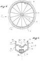
- FIG. 1 represents a wheel 1 comprising in a known manner a rim 2 connected to a central hub 3 by two plies of spokes. Only the tablecloth with radius 4 is visible in Figure 1.
- the spokes are of any suitable type, straight or angled, and, they are arranged indifferently in a radial or crossed shelving mode. Furthermore, the wheel is equally a wheel front or rear wheel.
- the rim is produced from a curved profile, the two of which ends are preferably joined by welding, in order to obtain a good seal level.
- the wheel 1 shown in Figure 1 is also equipped with a tire 5.
- the tire 5 is a tire of standard dimensions. Tire dimensions are by example defined by ISO 5775-1.
- such a tire has a central tread bordered by two lateral sides.
- the base of the lateral flanks or heel is slightly thicker, and contains a rigid or flexible rod whose length is defined.
- the wheel 1 shown in Figure 1 also has an inflation valve 6 which makes the object of the invention and will be described in detail later.
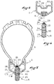
- FIG. 2 represents the profile of the rim 2 according to a preferred embodiment of work of the invention.
- the rim 2 is intended for tubeless mounting of the tire 5.
- the rim 2 has a known an upper bridge 10, a lower bridge 11 interconnected by two sides 12 and 13, of so as to form a box.
- the flanks are extended outwards by wings 14 and 15, which have at their end a bead 16, 17 which acts as a hook with respect to the sides of the tire.
- the rim 2 has holes 18 for hooking the spokes which are located only at the level of the lower deck 11.
- the upper deck 10 is not drilled with holes for the passage or hanging of shelves, which guarantees a seal perfect from the upper deck.
- the orifice 18 is tapped to allow the screwing of a nut or a ferrule attachment, as well as the tension radius adjustment. These elements are of all types appropriate.
- the lower bridge was drilled using a drilling technique by repression.
- this technique instead of being cut, the material is repelled so as to form a kind of chimney.
- the chimney prevents a weakening of the bridge at this level. She also offers an internal surface that can easily be tapped.
- This drilling method is not limiting, and any method of hanging the spokes is suitable.
- the upper bridge 10 present in its part median an annular groove 20.
- the groove is intended to facilitate mounting of the tire.
- this groove, its shape and its dimensions are not limiting for the invention.
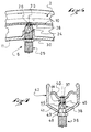
- FIG. 3 represents the rim 2 in cross section at the level of the hole provided for the valve 6 shown in FIG. 4. In a known manner this zone is located between two holes provided for hanging shelves.
- the valve 6 shown in FIG. 4 comprises a hollow body with an internal conduit 29 which goes right through it. Externally, the body is generally cylindrical, with a portion 24 which is provided for crossing the rim casing between the two bridges 10 and 11, and a portion 25 protruding outside the box. As is known, this second portion is intended to be connected to a pump or an external inflation means.
- An injection nozzle 26 of smaller diameter extends the portion 24.
- This nozzle injection is provided to cross the upper bridge 10 of the rim.
- the junction between the end piece 26 and the portion 24 forms a shoulder 27.
- a seal, for example an O-ring 28 is engaged on the injection nozzle possibly at a groove.
- This joint is intended to be pressed between the shoulder 27 and the upper bridge of the rim and to produce tightness at this level.
- the valve body has an internal conduit 29 which cross it right through in the longitudinal direction that the valve defines.
- the portion 24 of the valve body or the injection nozzle 26 is equipped assembly means provided to cooperate with complementary means of one of the rim 10 or 11 decks.
- the illustrated embodiment shows a portion 24 threaded on its outer surface. This thread is intended to be screwed into a threaded hole in the rim. However, like this will be said later, other means than a thread may be suitable.
- the valve body has a ring 30.
- This ring is intended to bear against the external surface of the lower deck.
- the ring has a section hexagonal exterior, to allow the valve to be tightened in its housing or disassembly using a tool such as a wrench. Other means may also be suitable.
- the portion 25 of the valve provided for the connection of an inflation means and the internal valve mechanism are of any suitable nature.
- valves for cycle are defined by the ETRTO standard (European Tire and Rim Technical Organization).
- valve body according to the present invention can be provided so that its portion 25 in projection externally and internally has the usual dimensions to receive a valve of a known type and in order to be able to be connected to pumps or other means of usual inflation.
- valve body as previously described, provided for receive an insert which would fulfill these connection and sealing functions.
- valve bodies at least those of the automotive type, have a threaded end to receive a plug.
- This thread located in the second portion of the body could be extended towards the injection nozzle. So the first and the second portion would be threaded in line with each other, at the same step.
- the ring 30 can be a threaded insert which is screwed onto the body and which acts like a lock nut.
- the rim is pierced with an orifice 23 at its lower deck 11, and, in the extension, with a orifice 22 located at the bridge 10, at the bottom of the groove 20.
- the orifice 23 is drilled and tapped at diameter and pitch of the thread of zone 24 of valve 6.
- this orifice is produced by the same technique of drilling by delivery. than the one used for hanging the shelves, so as to form a chimney which is then tapped.
- the internal diameter of the chimney and the thread pitch are adapted to dimensions of the portion 24 of the valve and the pitch of its thread.
- the orifice 22 corresponds to the diameter of the injection nozzle 26.
- the length of the nozzle is preferably determined so that the end piece crosses the bridge 22 and that its end is flush with the external surface of the upper deck, i.e. the bottom of the groove 20 or either in shrinkage, taking into account the thickness of the seal 28 and its crushing upon tightening. This is done in order not to interfere with the fitting of the tire.
- the shoulder 27 compresses the seal 28 against the wall of the bridge 10. The seal ensures in these conditions the seal between the inside of the tire and the channel 29 of the valve.
- the screw mounting mode ensures very good support of the valve body in the rim. Indeed, there is a mechanical assembly between the valve and the rim, and the valve is held at the level of the two rim bridges.
- the ring 30 is provided to tighten against the bridge 11, and brake in this way tightening the valve.
- the aim is to avoid excessive crushing of the seal 28 which could damage it, and also avoid excessive tightening which could constrain locally the two bridges at the distance.
- either the ring 30 is located along the body at a distance from the shoulder 27 approximately equal to the distance between the two bridges 10 and 11, or it is movable along the body and it is pressed against the bridge lower in the way of a lock nut.
- the mounting and dismounting of the valve 6 are made very simply by screwing and unscrewing from the outside of the rim.
- the assembly and disassembly operations are completely independent of the presence or absence of the tire.
- the valve could be exchanged without requiring disassembly of the tire.
- a tire could be dismantled and reassembled without having to touch the valve.
- the sidewalls of the tire are engaged on one of the wings of the rim, and they are kept engaged in the throat.
- the fact that the valve does not protrude inside throat is advantageous because it does not interfere with this operation.
- the natural elasticity of the tire causes the sides to stick against the edges of the groove.
- the injection nozzle 26 opens into the volume of the tire.
- a relative seal exists between the tire and the edges of the groove. This tightness becomes stronger as you go the primary inflation of the tire, until, under the effect of the pressure, the sidewalls of the tire cross the edges of the throat and press against the wings.
- valve 36 has a threaded injection nozzle 37, and a portion 38 intended to pass through the rim casing which is smooth.
- the rim 42 has a box with a lower bridge 41 and an upper bridge 40.
- the lower bridge 41 has a bore 43, drilled to the diameter of the portion 38, and the bridge upper 40 a hole 44 drilled by discharge and tapped to the diameter of the injection nozzle 37.
- an annular seal 45 is provided to be compressed between the edge of hole 44 and a shoulder 46 at the junction between the injection nozzle and the rest of the body.
- a ring 48 similar to the ring 30 cooperates with the bridge lower 41 of the rim to limit the tightening of the valve, to avoid crushing of the seal or excessive constraints on the distance of the bridges.
- the injection nozzle 37 is flush with the surface external of the upper deck 40, or is recessed with respect thereto.
- the invention is not limited to the various embodiments which have been described, and other variations are possible.
- the invention could be applied to other rim profiles as that which has been described and shown.
- the nature and method of mounting the seal 28 could also be different.
Landscapes
- Engineering & Computer Science (AREA)
- Mechanical Engineering (AREA)
- Check Valves (AREA)
Applications Claiming Priority (2)
| Application Number | Priority Date | Filing Date | Title |
|---|---|---|---|
| FR9709929A FR2766424B1 (fr) | 1997-07-25 | 1997-07-25 | Valve et jante pour roue de bicyclette prevues pour un montage tubeless |
| FR9709929 | 1997-07-25 |
Publications (1)
| Publication Number | Publication Date |
|---|---|
| EP0893285A1 true EP0893285A1 (de) | 1999-01-27 |
Family
ID=9509975
Family Applications (1)
| Application Number | Title | Priority Date | Filing Date |
|---|---|---|---|
| EP98112980A Withdrawn EP0893285A1 (de) | 1997-07-25 | 1998-07-13 | Ventil und Felge eines Fahrradrades für schlauchlose Reifen |
Country Status (3)
| Country | Link |
|---|---|
| US (1) | US6119746A (de) |
| EP (1) | EP0893285A1 (de) |
| FR (1) | FR2766424B1 (de) |
Cited By (2)
| Publication number | Priority date | Publication date | Assignee | Title |
|---|---|---|---|---|
| EP1176035A3 (de) * | 2000-07-27 | 2003-01-15 | Bridgeport Brass S.P.A. | Ventil für Fahrradreifen ohne Schlauch |
| US6820668B2 (en) | 2000-08-03 | 2004-11-23 | Campagnolo S.R.L. | Rim for a bicycle wheel with tubeless tire |
Families Citing this family (7)
| Publication number | Priority date | Publication date | Assignee | Title |
|---|---|---|---|---|
| FR2766419B1 (fr) | 1997-07-25 | 1999-10-01 | Mavic Sa | Jante de bicyclette prevue pour un montage tubeless et roue de bicyclette |
| FR2825319B1 (fr) | 2001-06-05 | 2003-09-19 | Mavic Sa | Procede de construction d'une roue a rayons sous tension et roue a rayons sous tension destinee a un vehicule a deux roues |
| US20040189548A1 (en) * | 2003-03-26 | 2004-09-30 | Ngk Insulators, Ltd. | Circuit element, signal processing circuit, control device, display device, method of driving display device, method of driving circuit element, and method of driving control device |
| US20050210675A1 (en) * | 2004-03-26 | 2005-09-29 | Price Chad N | Sealed tubeless tire bicycle wheel |
| US7431404B2 (en) * | 2005-08-05 | 2008-10-07 | Shimano Inc. | Bicycle having annular sealing member |
| DE102012103455A1 (de) | 2012-04-19 | 2013-10-24 | Yuan-Hung WEN | Ventil- und Felgenbandanordnung |
| US10807424B2 (en) * | 2018-01-05 | 2020-10-20 | Specialized Bicycle Components, Inc. | Tubeless valve assembly |
Citations (10)
| Publication number | Priority date | Publication date | Assignee | Title |
|---|---|---|---|---|
| GB814371A (en) * | 1956-05-08 | 1959-06-03 | Alexander Wilson Morrison | Improvements in and relating to pneumatic tyre and wheel assemblies |
| DE1077548B (de) * | 1960-03-10 | Daimler-Benz Aktiengesellschaft, Stuttgart-Untertürkheim | Einrichtung zur selbsttätigen Regelung des Reifendruckes bei Fahrzeugen, insbesondere bei Kraftfahrzeugen mit schlauchlosen Reifen | |
| US3008770A (en) | 1956-12-19 | 1961-11-14 | American Mach & Foundry | Rim for tubeless bicycle tires |
| EP0240241A2 (de) * | 1986-03-28 | 1987-10-07 | Sumitomo Rubber Industries Limited | Reifen und Felge für Motorräder |
| DE3727051A1 (de) | 1987-08-13 | 1989-02-23 | Sumitomo Rubber Ind | Anordnung aus schlauchlosem reifen und radfelge fuer kraftraeder |
| WO1993009963A1 (de) | 1991-11-15 | 1993-05-27 | Klaus Kleinhoff | Speichenrad, felge und nippel für speichenrad und verfahren zur herstellung von felgen für ein speichenrad |
| EP0615865A1 (de) | 1993-03-15 | 1994-09-21 | Jorge Nadal Aloy | Abdichtungsvorrichtung für Speicherräder mit schlauchlosen Reifen |
| EP0616911A2 (de) | 1993-03-26 | 1994-09-28 | Jorge Nadal Aloy | Anordnung zum Aufpumpen von Schlauchlosen Reifen |
| EP0633150A1 (de) * | 1993-07-07 | 1995-01-11 | Hutchinson | Dichtungsvorrichtung für Speichenrad und Rad mit dieser Dichtungsvorrichtung |
| FR2744953A1 (fr) * | 1996-02-19 | 1997-08-22 | Hutchinson | Jante de roue a rayons destinee a etre equipee d'un pneumatique sans chambre, et roue a rayons ainsi equipee |
Family Cites Families (23)
| Publication number | Priority date | Publication date | Assignee | Title |
|---|---|---|---|---|
| US514412A (en) * | 1894-02-06 | Half to charles t | ||
| US1426401A (en) * | 1921-04-06 | 1922-08-22 | Christian J Muller | Replacement valve |
| US1738927A (en) * | 1926-12-02 | 1929-12-10 | Marie Therese Elisabeth Salern | Valve for pneumatic tires |
| US1726243A (en) * | 1928-09-24 | 1929-08-27 | John M Scott | Signal for pneumatic tires |
| US1957866A (en) * | 1931-03-06 | 1934-05-08 | F H Watson Company | Stub type valve stem |
| US2228984A (en) * | 1938-05-07 | 1941-01-14 | Bridgeport Brass Co | Pneumatic tire valve |
| US2236585A (en) * | 1939-02-25 | 1941-04-01 | Scovill Manufacturing Co | Tire valve |
| US2937905A (en) * | 1955-11-29 | 1960-05-24 | Altenburger Karl | Spoke connection for tubeless tire rim |
| DE1976938U (de) * | 1967-09-30 | 1968-01-11 | Alligator Ventilfabrik Ges Mit | Ventileinsatz, insbesondere fuer luftreifenventile. |
| US3656531A (en) * | 1970-02-10 | 1972-04-18 | Chain Bike Corp | Wheel for a vehicle |
| US3889530A (en) * | 1973-06-04 | 1975-06-17 | Gary R Bluem | Fluid pressure testing apparatus |
| US4557308A (en) * | 1983-01-17 | 1985-12-10 | Scovil Inc. | Tire valve and low pressure indicator |
| US5064250A (en) * | 1988-06-17 | 1991-11-12 | Sugino Cycle Industries, Ltd. | Wheel for light vehicle and disc used therefor |
| DE4231539A1 (de) * | 1991-12-07 | 1993-06-09 | Jochen 8221 Tacherting De Klieber | Laufrad fuer ein fahrzeug |
| FR2693672B1 (fr) * | 1992-07-15 | 1994-11-04 | Mavic | Procédé de fabrication d'une jante pour cycle et jante réalisée avec ce procédé. |
| US5499864A (en) * | 1993-06-16 | 1996-03-19 | Klein Bicycle Corporation | Bicycle wheel rims |
| US5490719A (en) * | 1993-12-17 | 1996-02-13 | Wear And Tear, Inc. | Racing wheel |
| US5509438A (en) * | 1994-06-08 | 1996-04-23 | Spinergy Inc. | Air valve adapter |
| FR2727356A1 (fr) * | 1994-11-30 | 1996-05-31 | Mavic Sa | Jante de velo et roue comprenant une telle jante |
| US5653510A (en) * | 1996-02-21 | 1997-08-05 | Syncros Applied Technology Incorporated | Wheel rims |
| US5746850A (en) * | 1996-04-26 | 1998-05-05 | Luscher; Marcus P. | Double inner tube and valve system |
| US5941606A (en) * | 1996-12-20 | 1999-08-24 | Chen; Yung-Tang | Wheel adapted to be used in a bicycle |
| US5806935A (en) * | 1996-12-30 | 1998-09-15 | Shermeister; Chris J. | Tension-lock system for spokes in spoked wheels |
-
1997
- 1997-07-25 FR FR9709929A patent/FR2766424B1/fr not_active Expired - Fee Related
-
1998
- 1998-07-13 EP EP98112980A patent/EP0893285A1/de not_active Withdrawn
- 1998-07-24 US US09/121,703 patent/US6119746A/en not_active Expired - Fee Related
Patent Citations (10)
| Publication number | Priority date | Publication date | Assignee | Title |
|---|---|---|---|---|
| DE1077548B (de) * | 1960-03-10 | Daimler-Benz Aktiengesellschaft, Stuttgart-Untertürkheim | Einrichtung zur selbsttätigen Regelung des Reifendruckes bei Fahrzeugen, insbesondere bei Kraftfahrzeugen mit schlauchlosen Reifen | |
| GB814371A (en) * | 1956-05-08 | 1959-06-03 | Alexander Wilson Morrison | Improvements in and relating to pneumatic tyre and wheel assemblies |
| US3008770A (en) | 1956-12-19 | 1961-11-14 | American Mach & Foundry | Rim for tubeless bicycle tires |
| EP0240241A2 (de) * | 1986-03-28 | 1987-10-07 | Sumitomo Rubber Industries Limited | Reifen und Felge für Motorräder |
| DE3727051A1 (de) | 1987-08-13 | 1989-02-23 | Sumitomo Rubber Ind | Anordnung aus schlauchlosem reifen und radfelge fuer kraftraeder |
| WO1993009963A1 (de) | 1991-11-15 | 1993-05-27 | Klaus Kleinhoff | Speichenrad, felge und nippel für speichenrad und verfahren zur herstellung von felgen für ein speichenrad |
| EP0615865A1 (de) | 1993-03-15 | 1994-09-21 | Jorge Nadal Aloy | Abdichtungsvorrichtung für Speicherräder mit schlauchlosen Reifen |
| EP0616911A2 (de) | 1993-03-26 | 1994-09-28 | Jorge Nadal Aloy | Anordnung zum Aufpumpen von Schlauchlosen Reifen |
| EP0633150A1 (de) * | 1993-07-07 | 1995-01-11 | Hutchinson | Dichtungsvorrichtung für Speichenrad und Rad mit dieser Dichtungsvorrichtung |
| FR2744953A1 (fr) * | 1996-02-19 | 1997-08-22 | Hutchinson | Jante de roue a rayons destinee a etre equipee d'un pneumatique sans chambre, et roue a rayons ainsi equipee |
Cited By (3)
| Publication number | Priority date | Publication date | Assignee | Title |
|---|---|---|---|---|
| EP1176035A3 (de) * | 2000-07-27 | 2003-01-15 | Bridgeport Brass S.P.A. | Ventil für Fahrradreifen ohne Schlauch |
| US6820668B2 (en) | 2000-08-03 | 2004-11-23 | Campagnolo S.R.L. | Rim for a bicycle wheel with tubeless tire |
| CZ298007B6 (cs) * | 2000-08-03 | 2007-05-23 | Campagnolo Srl | Sestava ráfku a ventilu pro kolo jízdního kola |
Also Published As
| Publication number | Publication date |
|---|---|
| FR2766424A1 (fr) | 1999-01-29 |
| US6119746A (en) | 2000-09-19 |
| FR2766424B1 (fr) | 1999-10-01 |
Similar Documents
| Publication | Publication Date | Title |
|---|---|---|
| EP0893280B1 (de) | Fahrradnabe für die Montierung eines schlauchlosen Reifens und Fahrradrad | |
| BE1015382A3 (fr) | Jante pour une roue de bicyclette avec un pneu sans chambre a air. | |
| EP0818328A1 (de) | Bohrungsverfahren für Speichenrad,Felge gebohrt nach dem Verfahren,Einsatz zur Ausrüstung der Felge und Rad insbesondere für ein Zweirad | |
| FR2810582A1 (fr) | Dispositif d'accrochage d'un rayon a la jante d'une roue de bicyclette | |
| EP0878328B1 (de) | Halbhohlreifen und Walze mit solchen Reifen | |
| FR2536705A1 (fr) | Roue en matiere plastique pour bicyclettes ou analogues | |
| FR2766424A1 (fr) | Valve et jante pour roue de bicyclette prevues pour un montage tubeless | |
| EP0790141A1 (de) | Felge eines Speichenrades für schlauchlose Reifen und damit ausgerüstetes Speichenrad | |
| FR2787064A1 (fr) | Valve de gonflage pour une roue de bicyclette de type sans chambre a air | |
| EP1997648A1 (de) | Vorrichtung für schlauchlose Reifen | |
| FR2765150A1 (fr) | Jante pour roue de bicyclette | |
| FR2990405A1 (fr) | Potence de cycle a chape de serrage | |
| FR2701744A1 (fr) | Module de ressort à air pour un amortisseur et procédé de montage du module de ressort à air. | |
| FR2493235A1 (fr) | Pneumatique pour bicyclettes, du type couramment appele " boyau " pouvant etre utilise sur des jantes de type different | |
| FR2576388A1 (fr) | Dispositif pour le raccordement axial de deux tubes sans manchon | |
| EP3003741B1 (de) | Reifenkammer | |
| EP0791490B1 (de) | Reifenventil mit elliptischem Sitz | |
| FR2816548A1 (fr) | Procede de fabrication d'une jante de bicyclette prevue pour un montage sans chambre a air et jante obtenue par la mise en oeuvre du procede | |
| FR2885008A1 (fr) | Roue de reglage de profondeur et outil de travail du sol equipe d'une telle roue | |
| EP1122433A1 (de) | Schnellanschluss für das Aufpumpen eines Reifens und Fahrradpumpe mit Schnellanschluss | |
| FR2903752A1 (fr) | Valve de pneumatique. | |
| WO2012107697A1 (fr) | Dispositif de gonflage | |
| WO2021083913A1 (fr) | Pointeau de dosage pour amortisseur de type oleopneumatique | |
| CA2217467A1 (fr) | Dispositif de roulage a plat pour vehicule automobile, en particulier pour vehicule de tourisme | |
| FR2745232A1 (fr) | Adaptateur pour le rayonnage de roues a rayons montees avec des pneumatiques sans chambre |
Legal Events
| Date | Code | Title | Description |
|---|---|---|---|
| PUAI | Public reference made under article 153(3) epc to a published international application that has entered the european phase |
Free format text: ORIGINAL CODE: 0009012 |
|
| AK | Designated contracting states |
Kind code of ref document: A1 Designated state(s): BE CH DE ES IT LI NL PT |
|
| AX | Request for extension of the european patent |
Free format text: AL;LT;LV;MK;RO;SI |
|
| AKX | Designation fees paid |
Free format text: BE CH DE ES IT LI NL PT |
|
| STAA | Information on the status of an ep patent application or granted ep patent |
Free format text: STATUS: THE APPLICATION IS DEEMED TO BE WITHDRAWN |
|
| 18D | Application deemed to be withdrawn |
Effective date: 19990728 |