EP0893288A1 - Suspension à bras latéral pour automobiles - Google Patents
Suspension à bras latéral pour automobiles Download PDFInfo
- Publication number
- EP0893288A1 EP0893288A1 EP98890206A EP98890206A EP0893288A1 EP 0893288 A1 EP0893288 A1 EP 0893288A1 EP 98890206 A EP98890206 A EP 98890206A EP 98890206 A EP98890206 A EP 98890206A EP 0893288 A1 EP0893288 A1 EP 0893288A1
- Authority
- EP
- European Patent Office
- Prior art keywords
- wheel
- wishbone
- camber
- axis
- point
- Prior art date
- Legal status (The legal status is an assumption and is not a legal conclusion. Google has not performed a legal analysis and makes no representation as to the accuracy of the status listed.)
- Granted
Links
Images

Classifications
-
- B—PERFORMING OPERATIONS; TRANSPORTING
- B60—VEHICLES IN GENERAL
- B60G—VEHICLE SUSPENSION ARRANGEMENTS
- B60G3/00—Resilient suspensions for a single wheel
- B60G3/18—Resilient suspensions for a single wheel with two or more pivoted arms, e.g. parallelogram
- B60G3/20—Resilient suspensions for a single wheel with two or more pivoted arms, e.g. parallelogram all arms being rigid
- B60G3/26—Means for maintaining substantially-constant wheel camber during suspension movement ; Means for controlling the variation of the wheel position during suspension movement
-
- B—PERFORMING OPERATIONS; TRANSPORTING
- B60—VEHICLES IN GENERAL
- B60G—VEHICLE SUSPENSION ARRANGEMENTS
- B60G3/00—Resilient suspensions for a single wheel
- B60G3/18—Resilient suspensions for a single wheel with two or more pivoted arms, e.g. parallelogram
- B60G3/20—Resilient suspensions for a single wheel with two or more pivoted arms, e.g. parallelogram all arms being rigid
- B60G3/22—Resilient suspensions for a single wheel with two or more pivoted arms, e.g. parallelogram all arms being rigid a rigid arm forming the axle housing
-
- B—PERFORMING OPERATIONS; TRANSPORTING
- B60—VEHICLES IN GENERAL
- B60G—VEHICLE SUSPENSION ARRANGEMENTS
- B60G2200/00—Indexing codes relating to suspension types
- B60G2200/10—Independent suspensions
- B60G2200/14—Independent suspensions with lateral arms
- B60G2200/144—Independent suspensions with lateral arms with two lateral arms forming a parallelogram
-
- B—PERFORMING OPERATIONS; TRANSPORTING
- B60—VEHICLES IN GENERAL
- B60G—VEHICLE SUSPENSION ARRANGEMENTS
- B60G2200/00—Indexing codes relating to suspension types
- B60G2200/40—Indexing codes relating to the wheels in the suspensions
- B60G2200/46—Indexing codes relating to the wheels in the suspensions camber angle
-
- B—PERFORMING OPERATIONS; TRANSPORTING
- B60—VEHICLES IN GENERAL
- B60G—VEHICLE SUSPENSION ARRANGEMENTS
- B60G2204/00—Indexing codes related to suspensions per se or to auxiliary parts
- B60G2204/10—Mounting of suspension elements
- B60G2204/14—Mounting of suspension arms
- B60G2204/143—Mounting of suspension arms on the vehicle body or chassis
-
- B—PERFORMING OPERATIONS; TRANSPORTING
- B60—VEHICLES IN GENERAL
- B60G—VEHICLE SUSPENSION ARRANGEMENTS
- B60G2204/00—Indexing codes related to suspensions per se or to auxiliary parts
- B60G2204/40—Auxiliary suspension parts; Adjustment of suspensions
- B60G2204/42—Joints with cam surfaces
-
- B—PERFORMING OPERATIONS; TRANSPORTING
- B60—VEHICLES IN GENERAL
- B60G—VEHICLE SUSPENSION ARRANGEMENTS
- B60G2204/00—Indexing codes related to suspensions per se or to auxiliary parts
- B60G2204/40—Auxiliary suspension parts; Adjustment of suspensions
- B60G2204/422—Links for mounting suspension elements
-
- B—PERFORMING OPERATIONS; TRANSPORTING
- B60—VEHICLES IN GENERAL
- B60G—VEHICLE SUSPENSION ARRANGEMENTS
- B60G2204/00—Indexing codes related to suspensions per se or to auxiliary parts
- B60G2204/40—Auxiliary suspension parts; Adjustment of suspensions
- B60G2204/423—Rails, tubes, or the like, for guiding the movement of suspension elements
- B60G2204/4232—Sliding mounts
-
- B—PERFORMING OPERATIONS; TRANSPORTING
- B60—VEHICLES IN GENERAL
- B60G—VEHICLE SUSPENSION ARRANGEMENTS
- B60G2204/00—Indexing codes related to suspensions per se or to auxiliary parts
- B60G2204/62—Adjustable continuously, e.g. during driving
-
- B—PERFORMING OPERATIONS; TRANSPORTING
- B60—VEHICLES IN GENERAL
- B60G—VEHICLE SUSPENSION ARRANGEMENTS
- B60G2206/00—Indexing codes related to the manufacturing of suspensions: constructional features, the materials used, procedures or tools
- B60G2206/01—Constructional features of suspension elements, e.g. arms, dampers, springs
- B60G2206/10—Constructional features of arms
- B60G2206/11—Constructional features of arms the arm being a radius or track or torque or steering rod or stabiliser end link
- B60G2206/111—Constructional features of arms the arm being a radius or track or torque or steering rod or stabiliser end link of adjustable length
-
- B—PERFORMING OPERATIONS; TRANSPORTING
- B60—VEHICLES IN GENERAL
- B60G—VEHICLE SUSPENSION ARRANGEMENTS
- B60G2206/00—Indexing codes related to the manufacturing of suspensions: constructional features, the materials used, procedures or tools
- B60G2206/01—Constructional features of suspension elements, e.g. arms, dampers, springs
- B60G2206/10—Constructional features of arms
- B60G2206/122—Constructional features of arms the arm having L-shape
-
- B—PERFORMING OPERATIONS; TRANSPORTING
- B60—VEHICLES IN GENERAL
- B60G—VEHICLE SUSPENSION ARRANGEMENTS
- B60G2206/00—Indexing codes related to the manufacturing of suspensions: constructional features, the materials used, procedures or tools
- B60G2206/01—Constructional features of suspension elements, e.g. arms, dampers, springs
- B60G2206/50—Constructional features of wheel supports or knuckles, e.g. steering knuckles, spindle attachments
-
- B—PERFORMING OPERATIONS; TRANSPORTING
- B60—VEHICLES IN GENERAL
- B60G—VEHICLE SUSPENSION ARRANGEMENTS
- B60G2300/00—Indexing codes relating to the type of vehicle
- B60G2300/27—Racing vehicles, e.g. F1
Definitions
- the invention relates to a wheel suspension for motor vehicles, in particular for racing vehicles the wheels of an axle do not change camber when cornering or that The outer wheel of an axle has a negative one and the inner wheel has a positive one Take fall automatically.
- the rising of the axis arises from the fact that the Lateral force occurring on the outside wheel during cornering by a moment the very high reaction center, which is identical to the rolling center. Here then there is a positive fall on the outside wheel. In addition, that causes high roll center and associated roll stiffness strong weight shift from inside to Outer wheel, which reduces the adhesion of the axle. Because of this, this is Suspension no longer carried out.
- the transverse swing axis is said to be based on current knowledge be as close to the road as possible, which is the case with the subject of the invention Front and rear axles can be used simultaneously.
- US 4,515,390A shows a chassis design designed to ensure that the wheels of a vehicle as perpendicular to the road surface as possible when cornering stay. This is achieved in that the car body about an axis when cornering rotates which is stored in the front and rear sub-chassis, and with these via springs and damper is connected. The preload of the springs will be tried by means of this set that when cornering the sub-chassis and articulated wheels, if possible in remain in their original position to the road surface to maximize wheel grip.
- the Wheel suspension is a double wishbone suspension with equally long parallel links. This patent therefore has nothing to do with the subject matter of the invention.
- Patent EP 96 372 A2 deals with the steering of wheels with known ones Wheel suspensions, where a connecting link or a section of the suspension, which in the Length is adjustable, which causes steering of the wheels.
- the length is adjusted using Hydraulic or compressed air servos. It is a steering of wheels, and not to adjust the camber and this is not done automatically, but by servo.
- the wheel suspension according to the invention achieves this in that a telescopic Wishbone rotatable or a rigid wishbone using a crank, a long one Sliding guide, a sliding rotating guide or by means of an elastic link on the car body is articulated, and a wheel carrier is rigidly attached to the outer end of this wishbone.
- a wheel carrier can be in the extension of the axis of the first cross member or under one Angle to this extend below or above the first wishbone.
- To the Wheel carrier is a second wishbone pivoted, which at the other end Car body is articulated.
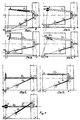
- FIG. 1 shows the first wishbone Q1 telescoping and the wheel carrier N under one Angle to Q1 angled downwards.
- Wishbone Q1 is articulated in B on the body, while wishbones Q2 are pivoted in A on the body and in C on the wheel carrier N. is. If you extend the axis of Q2 and cut it with the normal to the Wishbone Q1 through point B then you get the instantaneous pole MP Suspension. If you connect the instantaneous pole MP to the wheel contact center E and intersects the straight line thus obtained with the vertical body axis, then you get the roll center RZ, around which the car body turns when cornering.
- This Construction also applies to the following figures two, three and four.
- wishbone Q1 is mounted on the body of the vehicle in a sliding rotary guide, which is also due to an elastic bearing with a correspondingly shaped silent block for minor movements can be replaced.
- the wheel carrier N is angled downwards.
- FIG 3 shows articulation of the first wishbone Q1 by means of a crank R on the car body, the crank R up or down, at an angle to the first wishbone Q1, can be arranged pointing.
- the instantaneous pole arises where the extension of the Crank axis intersects with the extension of the axis of the second wishbone.
- Fig. 4 shows articulation of the first wishbone Q1 with a cam track on the car body where the instantaneous pole MP on the normal to the tangent to the sliding curve at point B lies where the normal lies with the extended axis of the second wishbone Q2 cuts.
- KM is the center of the curve of a circle at the cam track.
- FIGS. 5, 6 and 7 show the possible arrangements of the wheel carrier N, which is shown in FIG Extension of the wishbone Q1 is the angle to the axis of the wishbone Q1 has the value zero.
- the wheel carrier can also be an angle to the axis of the Take control arm Q1.
- Fig.6 the wheel carrier is angled downwards and has the Length a.
- Fig. 7 shows an upward-pointing wheel carrier of length a, where here cross the two wishbones Q1 and Q2. The roll center also results here as above cited.
- FIG. 9 shows the overall axis of a motor vehicle with the wheel suspension of the Subject of the invention in zero position and when cornering.
- cornering if one Centrifugal force acts on the center of gravity S, the carriage body W rolls around the roll center RZ Outside of the curve.
- the R1 and R2 wheels have no camber compared to the zero position, if the articulation point B of the wishbone Q1 lies on the semicircle K. If B is within the Semicircle K, as shown in Fig.9, then the outer wheel is negative and that Have positive camber on the inside of the wheel, which increases the Lateral leaders in curves. If the tire falls zero in curves, the tires stick better when braking and accelerating.
Landscapes
- Engineering & Computer Science (AREA)
- Mechanical Engineering (AREA)
- Vehicle Body Suspensions (AREA)
Applications Claiming Priority (3)
| Application Number | Priority Date | Filing Date | Title |
|---|---|---|---|
| AT123897 | 1997-07-21 | ||
| AT123897A AT405153B (de) | 1997-07-21 | 1997-07-21 | Radaufhängung für kfz |
| AT1238/97 | 1997-07-21 |
Publications (2)
| Publication Number | Publication Date |
|---|---|
| EP0893288A1 true EP0893288A1 (fr) | 1999-01-27 |
| EP0893288B1 EP0893288B1 (fr) | 2003-04-23 |
Family
ID=3509602
Family Applications (1)
| Application Number | Title | Priority Date | Filing Date |
|---|---|---|---|
| EP19980890206 Expired - Lifetime EP0893288B1 (fr) | 1997-07-21 | 1998-07-15 | Suspension à bras latéral pour automobiles |
Country Status (3)
| Country | Link |
|---|---|
| EP (1) | EP0893288B1 (fr) |
| AT (1) | AT405153B (fr) |
| DE (1) | DE59808014D1 (fr) |
Cited By (1)
| Publication number | Priority date | Publication date | Assignee | Title |
|---|---|---|---|---|
| ITBO20120004A1 (it) * | 2012-01-05 | 2013-07-06 | Ferrari Spa | Metodo di controllo degli angoli di convergenza e campanatura delle sospensioni posteriori attive di una vettura |
Families Citing this family (1)
| Publication number | Priority date | Publication date | Assignee | Title |
|---|---|---|---|---|
| DE102017204853A1 (de) | 2016-11-28 | 2018-05-30 | Hans-Jürgen Schulze | Mehrspuriges Kraftfahrzeug |
Citations (7)
| Publication number | Priority date | Publication date | Assignee | Title |
|---|---|---|---|---|
| DE642192C (de) | 1932-04-21 | 1937-02-25 | Daimler Benz Akt Ges | Kraftfahrzeug mit vier unabhaengig abgefederten Raedern |
| US3181883A (en) | 1960-10-26 | 1965-05-04 | Kolbe Joachim | Vehicle with curve-bank suspension |
| EP0096372A2 (fr) | 1982-06-07 | 1983-12-21 | Nissan Motor Co., Ltd. | Suspension pour véhicule moteur ou analogue, combinée avec un mécanisme de contrôle de la direction |
| US4515390A (en) | 1983-04-11 | 1985-05-07 | Greenberg William H | Chassis and suspension system for vehicles |
| EP0163382A1 (fr) | 1984-03-28 | 1985-12-04 | MacIsaac, William | Système de suspension de véhicule |
| JPS6456214A (en) * | 1987-08-26 | 1989-03-03 | Mazda Motor | Automobile suspension device |
| US5306034A (en) * | 1992-01-17 | 1994-04-26 | Gregory Buchanan | Vehicle wheel suspension system |
-
1997
- 1997-07-21 AT AT123897A patent/AT405153B/de not_active IP Right Cessation
-
1998
- 1998-07-15 DE DE59808014T patent/DE59808014D1/de not_active Expired - Fee Related
- 1998-07-15 EP EP19980890206 patent/EP0893288B1/fr not_active Expired - Lifetime
Patent Citations (7)
| Publication number | Priority date | Publication date | Assignee | Title |
|---|---|---|---|---|
| DE642192C (de) | 1932-04-21 | 1937-02-25 | Daimler Benz Akt Ges | Kraftfahrzeug mit vier unabhaengig abgefederten Raedern |
| US3181883A (en) | 1960-10-26 | 1965-05-04 | Kolbe Joachim | Vehicle with curve-bank suspension |
| EP0096372A2 (fr) | 1982-06-07 | 1983-12-21 | Nissan Motor Co., Ltd. | Suspension pour véhicule moteur ou analogue, combinée avec un mécanisme de contrôle de la direction |
| US4515390A (en) | 1983-04-11 | 1985-05-07 | Greenberg William H | Chassis and suspension system for vehicles |
| EP0163382A1 (fr) | 1984-03-28 | 1985-12-04 | MacIsaac, William | Système de suspension de véhicule |
| JPS6456214A (en) * | 1987-08-26 | 1989-03-03 | Mazda Motor | Automobile suspension device |
| US5306034A (en) * | 1992-01-17 | 1994-04-26 | Gregory Buchanan | Vehicle wheel suspension system |
Non-Patent Citations (1)
| Title |
|---|
| PATENT ABSTRACTS OF JAPAN vol. 013, no. 247 (M - 835) 8 June 1989 (1989-06-08) * |
Cited By (3)
| Publication number | Priority date | Publication date | Assignee | Title |
|---|---|---|---|---|
| ITBO20120004A1 (it) * | 2012-01-05 | 2013-07-06 | Ferrari Spa | Metodo di controllo degli angoli di convergenza e campanatura delle sospensioni posteriori attive di una vettura |
| EP2612773A1 (fr) * | 2012-01-05 | 2013-07-10 | FERRARI S.p.A. | Procédé de commande de l'angle de carrossage et de pincement dans des suspensions actives arrière d'un véhicule |
| US9216625B2 (en) | 2012-01-05 | 2015-12-22 | Ferrari S.P.A. | Method to control toe angle and camber angle in active rear suspensions of cars |
Also Published As
| Publication number | Publication date |
|---|---|
| DE59808014D1 (de) | 2003-05-28 |
| AT405153B (de) | 1999-06-25 |
| ATA123897A (de) | 1998-10-15 |
| EP0893288B1 (fr) | 2003-04-23 |
Similar Documents
| Publication | Publication Date | Title |
|---|---|---|
| EP2900493B1 (fr) | Suspension indépendante d'une roue d'un vehicule avec un bras en forme de ciseaux et un ressort | |
| DE3331247C2 (de) | Unabhängige Radaufhängung für Kraftfahrzeuge | |
| DE2103399C2 (de) | Radaufhängung für nicht angetriebene Kraftwagen-Hinterräder | |
| EP2497659B1 (fr) | Suspension de roue pour les roues arrière d'un véhicule automobile | |
| EP2720930B1 (fr) | Suspension de roue indépendante d'une roue arrière au moins légèrement orientable d'un véhicule à deux voies | |
| WO2003008212A1 (fr) | Essieu arriere d'un vehicule automobile dote de cinq bras oscillants | |
| EP0656270A1 (fr) | Suspension de roue | |
| DE4126761A1 (de) | Motorrad mit einer achsschenkellenkung | |
| DE102011077751A1 (de) | Einzelradaufhängung eines zumindest geringfügig lenkbaren Hinterrads eines zweispurigen Fahrzeugs | |
| DE102004039687B4 (de) | Vierlenker-Radaufhängung für ein Fahrzeug | |
| EP2874831B1 (fr) | Suspension de roue pour le pont arrière d'un véhicule | |
| EP1955875A1 (fr) | Suspension de roue pour véhicules automobiles | |
| DE102015212580A1 (de) | Radaufhängungsanordnung | |
| DE102009059029A1 (de) | Einzelradaufhängung eines insbesondere nicht lenkbaren Rades eines zweispurigen Fahrzeugs | |
| DE4219185A1 (de) | Kfz-hinterachse | |
| EP0893288B1 (fr) | Suspension à bras latéral pour automobiles | |
| DE1806332A1 (de) | Vertauschbare Radaufhaengung bei Kraftfahrzeugen | |
| DE2330229C2 (de) | Vorderachse für Kraftfahrzeuge | |
| DE102012221699A1 (de) | Radaufhängung für ein Fahrzeug mit aktiver Radsturzverstellung | |
| DE102018005047A1 (de) | Radaufhängung für ein Fahrzeug | |
| DE102016211385A1 (de) | Lenkersystem | |
| DE912534C (de) | Achsaufhaengung mit Schwinghalbachsen | |
| DE102015203567A1 (de) | Einzelradaufhängung sowie Hinterachse mit Einzelradaufhängungen für ein Fahrzeug | |
| DE19833399C1 (de) | Verbundlenkerachse mit Lenkerlagerung | |
| DE102012217264A1 (de) | Einzelradaufhängung eines Rades eines zweispurigen Fahrzeugs mit einem Scherenlenker |
Legal Events
| Date | Code | Title | Description |
|---|---|---|---|
| PUAI | Public reference made under article 153(3) epc to a published international application that has entered the european phase |
Free format text: ORIGINAL CODE: 0009012 |
|
| AK | Designated contracting states |
Kind code of ref document: A1 Designated state(s): DE FR GB IT |
|
| AX | Request for extension of the european patent |
Free format text: AL;LT;LV;MK;RO;SI |
|
| 17P | Request for examination filed |
Effective date: 19990616 |
|
| AKX | Designation fees paid |
Free format text: DE FR GB IT |
|
| 17Q | First examination report despatched |
Effective date: 20010925 |
|
| GRAH | Despatch of communication of intention to grant a patent |
Free format text: ORIGINAL CODE: EPIDOS IGRA |
|
| GRAH | Despatch of communication of intention to grant a patent |
Free format text: ORIGINAL CODE: EPIDOS IGRA |
|
| GRAA | (expected) grant |
Free format text: ORIGINAL CODE: 0009210 |
|
| AK | Designated contracting states |
Designated state(s): DE FR GB IT |
|
| PG25 | Lapsed in a contracting state [announced via postgrant information from national office to epo] |
Ref country code: IT Free format text: LAPSE BECAUSE OF FAILURE TO SUBMIT A TRANSLATION OF THE DESCRIPTION OR TO PAY THE FEE WITHIN THE PRESCRIBED TIME-LIMIT;WARNING: LAPSES OF ITALIAN PATENTS WITH EFFECTIVE DATE BEFORE 2007 MAY HAVE OCCURRED AT ANY TIME BEFORE 2007. THE CORRECT EFFECTIVE DATE MAY BE DIFFERENT FROM THE ONE RECORDED. Effective date: 20030423 Ref country code: GB Free format text: LAPSE BECAUSE OF FAILURE TO SUBMIT A TRANSLATION OF THE DESCRIPTION OR TO PAY THE FEE WITHIN THE PRESCRIBED TIME-LIMIT Effective date: 20030423 Ref country code: FR Free format text: LAPSE BECAUSE OF FAILURE TO SUBMIT A TRANSLATION OF THE DESCRIPTION OR TO PAY THE FEE WITHIN THE PRESCRIBED TIME-LIMIT Effective date: 20030423 |
|
| REG | Reference to a national code |
Ref country code: GB Ref legal event code: FG4D Free format text: NOT ENGLISH |
|
| REF | Corresponds to: |
Ref document number: 59808014 Country of ref document: DE Date of ref document: 20030528 Kind code of ref document: P |
|
| PGFP | Annual fee paid to national office [announced via postgrant information from national office to epo] |
Ref country code: DE Payment date: 20030723 Year of fee payment: 6 |
|
| GBV | Gb: ep patent (uk) treated as always having been void in accordance with gb section 77(7)/1977 [no translation filed] |
Effective date: 20030423 |
|
| PLBE | No opposition filed within time limit |
Free format text: ORIGINAL CODE: 0009261 |
|
| STAA | Information on the status of an ep patent application or granted ep patent |
Free format text: STATUS: NO OPPOSITION FILED WITHIN TIME LIMIT |
|
| 26N | No opposition filed |
Effective date: 20040126 |
|
| EN | Fr: translation not filed | ||
| PG25 | Lapsed in a contracting state [announced via postgrant information from national office to epo] |
Ref country code: DE Free format text: LAPSE BECAUSE OF NON-PAYMENT OF DUE FEES Effective date: 20050201 |