EP0893306B1 - Agencement de coffre destiné à être monté dans des véhicules automobiles, en particulier pour être aménagé dans le dossier du siège d'un tel véhicule - Google Patents
Agencement de coffre destiné à être monté dans des véhicules automobiles, en particulier pour être aménagé dans le dossier du siège d'un tel véhicule Download PDFInfo
- Publication number
- EP0893306B1 EP0893306B1 EP19980110382 EP98110382A EP0893306B1 EP 0893306 B1 EP0893306 B1 EP 0893306B1 EP 19980110382 EP19980110382 EP 19980110382 EP 98110382 A EP98110382 A EP 98110382A EP 0893306 B1 EP0893306 B1 EP 0893306B1
- Authority
- EP
- European Patent Office
- Prior art keywords
- transport container
- bolt
- container apparatus
- holding
- frame
- Prior art date
- Legal status (The legal status is an assumption and is not a legal conclusion. Google has not performed a legal analysis and makes no representation as to the accuracy of the status listed.)
- Expired - Lifetime
Links
- 238000009434 installation Methods 0.000 title claims description 4
- 230000000903 blocking effect Effects 0.000 claims description 2
- 230000000284 resting effect Effects 0.000 claims 1
- 239000004753 textile Substances 0.000 description 3
- 238000013459 approach Methods 0.000 description 2
- 239000007787 solid Substances 0.000 description 2
- 210000002105 tongue Anatomy 0.000 description 2
- 229910000831 Steel Inorganic materials 0.000 description 1
- 230000006835 compression Effects 0.000 description 1
- 238000007906 compression Methods 0.000 description 1
- 238000002347 injection Methods 0.000 description 1
- 239000007924 injection Substances 0.000 description 1
- 239000010959 steel Substances 0.000 description 1
Images





Classifications
-
- B—PERFORMING OPERATIONS; TRANSPORTING
- B60—VEHICLES IN GENERAL
- B60R—VEHICLES, VEHICLE FITTINGS, OR VEHICLE PARTS, NOT OTHERWISE PROVIDED FOR
- B60R5/00—Compartments within vehicle body primarily intended or sufficiently spacious for trunks, suit-cases, or the like
- B60R5/006—Compartments within vehicle body primarily intended or sufficiently spacious for trunks, suit-cases, or the like stowing or holding means for elongated articles, e.g. skis inside vehicles
Definitions
- the invention relates to a transport container device according to the preamble of Claim 1.
- a transport container device, and a ski bag facility is through DE 34 47 323 C2 became known.
- DE 34 47 323 C2 is a mounting arrangement provided in the form of a mounting frame, which materially connected in one piece Has locking tongues and locking abutments. With these locking abutments, the mounting frame inserted in a recess in the rear wall and then until the locking tabs snap into place pressed into a rear wall or trunk wall recess. In this way it is fast and attachment of the fastening frame to be carried out without tools possible. Disassembly can also be done without tools by direct actuation of the locking tongues happen, which, however, are not separate Have actuation handling (cf. DE 34 47 323 C2 Fig. 1).
- a system holding surface in a groove into which a holding frame, namely a plug-in frame, for holding the ski bag mouth area can be used.
- Ski bag mouth area and Holding frames thus form one on the system holding surface of the mounting frame adjacent counter system holding surface.
- this object solved in that the mounting frame two in Distance from each other, opposed to each other Directional system stopping areas, namely a first and a second system holding surface, forms, to which one or alternatively one Counter system holding surface of a holding frame can be created is, and that for releasable fixing of the holding frame on the respective plant holding area of each plant holding area at least one bolt is assigned.
- Essential for the transport container device according to the invention is first the vehicle side mounting frame to be attached. This forms two spaced apart, one inside the other system holding surfaces pointing in opposite directions, namely a first and second plant holding surface.
- the mounting frame e.g. the first system stopping area in the direction of travel in the front, i.e. into the passenger compartment, and the second System holding area to the rear, i.e. in the trunk inside, point.
- the invention has the possibility created, e.g. a transport container with the Counter system holding surface of his holding frame from the trunk forward to the rear-facing second system holding surface to add and there by means of at least of a latch to be releasably attached.
- a trunk side assembled container e.g. a cool box, could then use a dedicated Flap over the seat back and / or trunk wall side Loading opening must be accessible.
- the invention opens up the possibility of the counter frame holding surface on the holding frame side a container from the passenger compartment to the front pointing first plant-holding surface and there secure with at least one bolt.
- container could be a utensil portable offices, e.g. one fax machine, one Telephone system, a laptop or the like, record.
- the loading opening leading to the trunk can be at such a transport container also used be and if only to carry out electrical Cables.
- transport containers there are also transport containers conceivable that no use of the loading opening require.
- the invention also allows the possibility of both passenger side and on the trunk side, one transport container each of the mounting frame according to the invention releasably to back up.
- transport container in Any suitable container understood in the sense of the invention be it completely closed or be it is partially open, be it with solid walls or be flexible walls.
- a preferred embodiment according to the invention is that the mounting frame at least two spaced apart has hollow profile-like components, their cross-sectional profile is substantially U-shaped and their Profile webs connected to each other by a profile floor with their outer surfaces the first and the form a second system holding surface. Appropriately points the profile opening of the respective hollow profile Component to the outside.
- An advantageous variant of the invention exists in that the two hollow profile-like components by two each perpendicular to them extending connecting struts to a closed Fastening frames are interconnected. Furthermore, the invention provides that the two hollow profile-like components on the vehicle side essentially are mounted horizontally.
- the respective latch is expedient by means of at least to operate an actuating handle.
- the bolt is a swivel bolt or a sliding bolt is the one that is in contact with the system holding surface Engages behind the holding frame at a point that facing away from the counter-system holding surface of the holding frame is.
- the Latch formed by a resilient latch, which Can be part of a leaf spring element.
- the locking lug is in its grip behind the holding frame Blockable blocking position releasably.
- the invention provides for actuation of the latch first of all, that each latch has an operating handle assigned.
- the operating handle for the each latch on the side to be arranged which is also the system holding area assigned to the bolt the mounting arrangement is. If So a transport container is mounted from the passenger compartment can, according to the above-described inventive features the actuation handle from the passenger compartment be operated here.
- the invention holds for other applications an embodiment ready, after which the operating handle for both bars on the same side of the Mounting frame are provided.
- the invention does not necessarily provide that with Actuating handles provided latches, for example on two opposite sides, e.g. one closed mounting frame are provided.
- the invention can also be implemented if e.g. the lower side of the mounting frame is form-fitting is held, e.g. with a swivel motion allowing plug-in fastening. In this Case it will suffice to have at least one tie on the the upper side of the mounting frame.
- Embodiment is that one side of the mounting frame, e.g. above, at least one bolt is arranged, and that on the opposite side of the mounting frame, Side of the mounting frame e.g. below, also arranged at least one latch is that on one side of the mounting arrangement, e.g. above, at least one operating handle is arranged for at least one bolt, and that the on the diametrically opposite side of the Fixing frame provided latches together are motion-coupled.
- the bolt assigned to it is operated via a motion clutch, e.g. about a Bowden cable or via a linkage, at the same time that on the lower one Latch arranged on the side of the fastening frame also operated in the sense of release.
- a motion clutch e.g. about a Bowden cable or via a linkage
- FIG. 1 is a transport container device 10 in the rear seat back 11 of a passenger car sedan built in and with respect to the Direction of travel x behind a swiveling armrest 13 arranged, the rest position in a solid representation and their swung out operating position 1 to be seen in dashed lines is.
- a seat back frame made of pressed steel sections 12 also forms the one with a panel 14 provided trunk wall 15. So you have the trunk at 16 and the passenger compartment at 17 to introduce.
- a recess 18 is in the trunk wall 15 for receiving a mounting frame 19 of the transport container device 10 introduced.
- the mounting frame 19, a plastic injection molded part, for example, is in a manner not shown on the edge 20 of the Recess 18 fastened, in particular screw-fastened.
- the mounting frame 19 has an upper and a lower hollow profile-like component 21, 22.
- the hollow profile-like components 21, 22 are profiled in a U-shape and point with their respective profile opening 23, 24 to the outside, i.e. up and down.
- Each hollow profile-like component 21, 22 has a profile floor 25 and approximately staircase to the outside angled profile webs 26, 27.
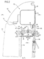
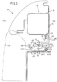
- FIGS. 2 and 3 form the profile webs 26, 27 system holding surfaces AH1 and AH2, which are opposite to each other Show directions. Namely, the first plant stopping area AH1 to passenger compartment 17 while the second system holding surface AH2 directed to the trunk 16 is.
- FIG. 1 and 3 show that a Holding frame H with a front counter system holding surface GA1 on the rear system holding surface AH2 of the mounting frame 19 abuts.
- swivel bolts 28, 29 are one Assembly grouped and on a common Bearing axis 30 within the hollow profile-like component 21 pivoted.
- the bearing axis 30 is by means of at least one console 61 on component 21 or 22 attached.
- Both swivel bolts 28, 29 are designed as a double lever to operate them each have a relatively short lever extension 31.
- Each lever extension 31 is of a separate one Actuating handle 32, 33 encompassed. If the operating handle 32 is pressed in the direction of F1, engages the operating handle 32 on the lever extension 31 of the pivot bolt 28 and lifts it its locking position upwards and gives in in this case, a swivel flap 34 free that the Handling a textile ski bag 35 serves if it is still in a storage space 36.
- the holding frame H described above thus serves in this Case of detachable attachment of the textile ski bag 35 on the mounting frame 19.
- Fig. 3 is only intended to show how the holding frame H on lower area of the arrangement.
- the operating handle 39 is via a fork 62 with both Lever extensions 31 of the swivel bolts 28, 29 coupled in motion. And that belongs to the one facing downwards Lever extension 31 to the pivot bolt 28 while the lever extension 31 pointing above with the swivel bolt 29 is in one piece.
- 4 is a rigid Container 40, e.g. a cool box, with the counter system holding surface GA1 of its holding frame H to the rear Attachment holding surface AH2 added and by means of Latch projection 37 of the pivot bolt 29 releasably locked.
- the rigid container 40 can therefore from the trunk 16 ago used in the mounting frame 19 become.
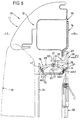
- FIG. 5 is a rigid container 40 from Passenger compartment 17 ago used in the mounting frame 19. Accordingly, the holding frame H is shown in FIG. 5 with its rear counter system holding surface GA2 on the front system holding surface AH1 of the mounting frame 19 on and is there by means of the bolt approach 37 of the pivot bolt 28 releasably held.
- FIG. 6 is in the Difference to the representation of FIG. 4 instead of Holding frame H of a rigid container 40 of the holding frame H of a textile ski bag 35 is shown, as it is already shown in Fig. 2.
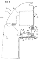
- Fig. 7 corresponds to the application to a Trunk 16 rigid container 40 the embodiment of FIG. 4.
- the Swivel bolt 29 according to FIG. 4 by a sliding bolt or cam 41 replaced, which contrary to Restoring force of a helical compression spring 42 in the pressure direction F3 can be moved upwards can and at the same time on a pressure finger 43 moved the swivel bolt 28 into its release position.
- Fig. 11 it is shown that in particular heavyweight containers 40 whose holding frame H using knurled screws R on the mounting frame 19 and anchored to the seat back frame 12 can be.
- the two hollow profile-like components 21 and 22 are by means of vertical connecting struts 48 to a closed mounting frame 19 together connected.
- a push rod 49 that has an axial guide slot 50 has, on guide cams 51, which the respective connecting strut 48 are formed, translationally corresponding to that designated by y Double arrow moved up and down. So if the actuating handle pivotally mounted on the axis 52 39 is actuated in the printing direction F2, engages behind the operating handle 39 with a lateral Projection 54 a lever extension 53 of the Swivel lock 29 and lifts it into its release position on.
- the pivot lever 29 presses with his Lever extension 31 at the same time on the lever extension 31 of the pivot bolt 28 to this also in his Relocate position. With this movement lifts a lifting finger 55 push rod 49 on its cam 56 up. At the same time, the push rod 49 also lifts its lower cam 57, the two lever extensions 31 the lower hook 28U, 29U on and operated this in the sense of loosening.
- All swivel bolts 28, 29, 28U, 29U are in Spring loaded in the direction of its locking position, for example by means of the in FIG and 14 shown leg springs 58.
- the holding frame H is part of an adapter plate 59 which optionally attached any container 40 can be, for example by means of a knurled screw connection 60th
Landscapes
- Engineering & Computer Science (AREA)
- Mechanical Engineering (AREA)
- Vehicle Step Arrangements And Article Storage (AREA)
Claims (16)
- Agencement de coffre (10) destiné à être monté dans des véhicules automobiles, par exemple dispositif de chargement traversant, en particulier pour le montage côté dossier de siège et paroi de coffre à bagages dans des voitures particulières, avec un cadre de fixation (19) à monter sur le bord (20) d'une ouverture de chargement traversant (18) située côté véhicule, cadre de fixation qui forme au moins une face de maintien en appui (AH1, AH2) s'étendant dans un plan, pour une face de maintien d'appui conjugué (GA1, GA2) d'un cadre de maintien (H) d'un coffre (35, 40), tel qu'un sac à skis (35) ou analogue (40), caractérisé en ce que le cadre de fixation (19) forme deux faces de maintien en appui (AH1, AH2), disposées à distance l'une de l'autre, tournées dans des directions (en 17, en 16) mutuellement opposées, précisément une première face de maintien en appui (AH1) et une deuxième face de maintien en appui (AH2) sur chacune desquelles, ou en alternance, peut être appliquée une face de maintien en appui conjuguée (GA1, GA2) d'un cadre de maintien (H), et en ce que, pour obtenir une fixation désolidarisable du cadre de maintien (H) sur la face de maintien en appui (AH1, AH2) respective, à chaque face de maintien en appui (AH1, AH2) est associé au moins un verrou (28, 29 ; 28U, 29U ; 41).
- Agencement de coffre selon la revendication 1, caractérisé en ce que le cadre de fixation (19) présente au moins deux composants (21, 22) du genre d'un profilé creux, disposés à distance et parallèlement l'un à l'autre, dont le profil de section transversale est sensiblement en forme de U et dont les nervures de profil (26, 27), reliées ensemble par un fond de profil (25), forment, par leurs faces extérieures, le première face de maintien en appui (AH1) et la deuxième face de maintien en appui (AH2).
- Agencement de coffre selon la revendication 2, caractérisé en ce que l'ouverture de profilé (23, 24) du composant (21, 22) du genre d'un profilé creux respectif est tourné vers l'extérieur.
- Agencement de coffre selon l'une des revendications 1 à 3, caractérisé en ce que les deux composants (21, 22) du genre d'un profilé creux sont reliés ensemble par deux entretoises de liaison (48) s'étendant chacune à angle droit de ceux-ci, pour former un cadre de fixation (19) fermé.
- Agencement de coffre selon l'une des revendications 1 à 4, caractérisé en ce que les deux composants (21, 22) du genre de profilés creux sont montés sensiblement horizontalement côté véhicule.
- Agencement de coffre selon l'une des revendications 1 à 5, caractérisé en ce que le verrou (28, 29; 28U, 29U; 41) est actionné à l'aide d'au moins une manette d'actionnement (32, 33, 39).
- Agencement de coffre selon l'une des revendications 1 à 6, caractérisé en ce que le verrou est un verrou pivotant (28, 29; 28U, 29U) ou un verrou coulissant (41) qui saisit par l'arrière le cadre de maintien (H) en appui sur la face de maintien en appui (par exemple AH2) en un emplacement (GA2) opposé à la face de maintien en appui conjuguée (GA1) du cadre de maintien (H).
- Agencement de coffre selon l'une des revendications 1 à 7, caractérisé en ce que le verrou est formé par un ergot d'encliquetage (44, 45) élastique.
- Agencement de coffre selon la revendication 8, caractérisé en ce que l'ergot d'encliquetage (44, 45) élastique est formé par un élément de ressort à lame.
- Agencement de coffre selon la revendication 8 ou la revendication 9, caractérisé en ce que l'ergot d'encliquetage (44, 45) est à bloquer de façon désolidarisable (en 46) à sa position de blocage à saisie par l'arrière du cadre de maintien (H).
- Agencement de coffre selon l'une des revendications 1 à 10, caractérisé en ce qu'une manette d'actionnement (32, 33) est associée à chaque verrou (28, 29).
- Agencement de coffre selon l'une des revendications 1 à 11, caractérisé en ce que la manette d'actionnement (32, 33), prévue pour le verrou (28, 29) respectif, est disposée du côté sur lequel se trouve la face de maintien en appui (AH1, AH2), associée au verrou (28, 29), du cadre de fixation (19).
- Agencement de coffre selon l'une des revendications 1 à 11, caractérisé en ce que les manettes d'actionnement pour les deux verrous sont prévues sur le même côté du cadre de fixation.
- Agencement de coffre selon la revendication 13, caractérisé en ce que les deux manettes d'actionnement sont regroupées en une manette d'actionnement (39) unique, desservant en même temps les deux verrous (28, 29).
- Agencement de coffre selon l'une des revendications 1 à 14, caractérisé en ce que, sur un côté du cadre de fixation 19, par exemple en partie haute (en 21), est disposé au moins un verrou (28, 29), tandis que, sur le côté, diamétralement opposé au verrou, du dispositif de fixation, par exemple en partie basse (en 22) n'est prévu qu'un logement à ajustement de forme, assurant le maintien du cadre de maintien (H) sur le cadre de fixation (19).
- Agencement de coffre selon l'une des revendications 1 à 14, caractérisé en ce que, sur un côté du dispositif de fixation (19), par exemple en partie haute (en 21), est disposé au moins un verrou (28,29), et en ce que sur le côté opposé du cadre de fixation (19), par exemple en partie basse (en 22), est également disposé au moins un verrou (28U, 29U), en ce que, sur un côté du dispositif de fixation, par exemple en partie haute (en 21), est disposée au moins une manette d'actionnement (39) pour au moins un verrou (28, 29), et en ce que les verrous (28U, 29U), prévus sur les côtés diamétralement opposés (par exemple en 22) du cadre de fixation (19), sont couplés cinématiquement ensemble.
Applications Claiming Priority (2)
| Application Number | Priority Date | Filing Date | Title |
|---|---|---|---|
| DE19727499 | 1997-06-27 | ||
| DE1997127499 DE19727499C1 (de) | 1997-06-27 | 1997-06-27 | Transportbehälter-Einrichtung für den Einbau in Kraftfahrzeuge, insbesondere für den sitzlehnenseitigen Einbau in Personenkraftwagen |
Publications (3)
| Publication Number | Publication Date |
|---|---|
| EP0893306A2 EP0893306A2 (fr) | 1999-01-27 |
| EP0893306A3 EP0893306A3 (fr) | 2000-04-26 |
| EP0893306B1 true EP0893306B1 (fr) | 2002-11-13 |
Family
ID=7833913
Family Applications (1)
| Application Number | Title | Priority Date | Filing Date |
|---|---|---|---|
| EP19980110382 Expired - Lifetime EP0893306B1 (fr) | 1997-06-27 | 1998-06-06 | Agencement de coffre destiné à être monté dans des véhicules automobiles, en particulier pour être aménagé dans le dossier du siège d'un tel véhicule |
Country Status (3)
| Country | Link |
|---|---|
| EP (1) | EP0893306B1 (fr) |
| DE (1) | DE19727499C1 (fr) |
| ES (1) | ES2186049T3 (fr) |
Families Citing this family (8)
| Publication number | Priority date | Publication date | Assignee | Title |
|---|---|---|---|---|
| DE19840503C1 (de) | 1998-09-07 | 1999-12-09 | Butz Peter Verwaltung | Transportvorrichtung, z. B. für Personen- und Kombinationskraftwagen |
| DE19924921B4 (de) * | 1999-05-31 | 2007-10-11 | Volkswagen Ag | Audio-Anlage in einem Fahrzeug |
| DE10132081B9 (de) * | 2000-08-30 | 2006-05-11 | Bos Gmbh & Co. Kg | Transportbehälter-Einrichtung für Fahrzeuge, wie z.B. Durchladeeinrichtung |
| DE10113619C2 (de) * | 2001-03-20 | 2003-03-06 | Butz Peter Verwaltung | Transportbehälter-Einrichtung für den Einbau in Kraftfahrzeuge, wie z.B. Durchladeinrichtung |
| DE10354160B4 (de) * | 2003-11-19 | 2005-08-25 | Bos Gmbh & Co. Kg | Transportbehälter-Einrichtung für Fahrzeuge |
| DE10354162A1 (de) * | 2003-11-19 | 2005-06-30 | Bos Gmbh & Co. Kg | Transportbehälter-Einrichtung für Fahrzeuge |
| DE10357356A1 (de) * | 2003-12-09 | 2005-07-07 | Sitech Sitztechnik Gmbh | Vorrichtung zum Aufnehmen von Gegenständen für den Einbau in ein Fahrzeug |
| DE102004008828B3 (de) * | 2004-02-20 | 2005-08-04 | Bos Gmbh & Co. Kg | Transportbehälter-Einrichtung für Fahrzeuge, wie z.B. Durchlade-Einrichtung, insbesondere für den sitzlehnen- oder kofferraumwandseitigen Einbau in Personenkraftwagen |
Family Cites Families (6)
| Publication number | Priority date | Publication date | Assignee | Title |
|---|---|---|---|---|
| DE1849156U (de) * | 1962-01-08 | 1962-03-29 | Friedrich Hornung | Behaelteranordnung fuer die unterbringung von skiern in kraftwagen. |
| DE3447323A1 (de) * | 1984-12-24 | 1986-06-26 | Eugen Otto 4010 Hilden Butz | Volumenveraenderlicher gepaeckraum im heck von kraftfahrzeugen |
| DE3625666C2 (de) * | 1986-07-29 | 1995-01-05 | Bayerische Motoren Werke Ag | Verriegelungsvorrichtung für eine Abdeckplatte einer Durchladeöffnung in einem Kraftfahrzeuginnenraum |
| DE3738931A1 (de) * | 1987-11-17 | 1989-06-01 | Opel Adam Ag | Vorrichtung zum transport von laenglichen gegenstaenden, insbesondere skiern, in einem personenkraftwagen |
| DE4106973C2 (de) * | 1991-03-05 | 1994-10-06 | Daimler Benz Ag | Transportvorrichtung, insbesondere für Skier in einem Kraftwagen |
| US5628543A (en) * | 1995-09-27 | 1997-05-13 | Hoover Universal, Inc. | Vehicle seat back having ski tote bag and trunk pass through |
-
1997
- 1997-06-27 DE DE1997127499 patent/DE19727499C1/de not_active Expired - Fee Related
-
1998
- 1998-06-06 ES ES98110382T patent/ES2186049T3/es not_active Expired - Lifetime
- 1998-06-06 EP EP19980110382 patent/EP0893306B1/fr not_active Expired - Lifetime
Also Published As
| Publication number | Publication date |
|---|---|
| DE19727499C1 (de) | 1998-07-09 |
| EP0893306A3 (fr) | 2000-04-26 |
| ES2186049T3 (es) | 2003-05-01 |
| EP0893306A2 (fr) | 1999-01-27 |
Similar Documents
| Publication | Publication Date | Title |
|---|---|---|
| DE4329997B4 (de) | Einrichtung zum Ent- und Verriegeln von zumindest zwei mit Abstand zueinander angeordneten, schwenkbaren Hauben eines Kraftfahrzeuges | |
| DE19825708B4 (de) | Crashsicheres Fahrzeugtürschloß | |
| EP1184224A2 (fr) | Dispositif à conteneur de transport pour véhicules, p.ex. dispositif à évidement de chargement | |
| DE10144166B4 (de) | Schloss für eine Kraftfahrzeugtür | |
| DE4217140A1 (de) | Schloß an einer Fahrzeugtür | |
| EP0713806A1 (fr) | Dispositif de fermeture/de retenue pour une véhicule automobile | |
| DE102007013081B4 (de) | Armlehne, insbesondere für Kraftfahrzeuge | |
| EP0893306A2 (fr) | Agencement de coffre destiné à être monté dans des véhicules automobiles, en particulier pour être aménagé dans le dossier du siège d'un tel véhicule | |
| DE102016218014A1 (de) | Sitztiefenversteller | |
| EP1355022B1 (fr) | Dispositif d'actionnement pour la serrure d'une porte, d'un capot ou similaires, notamment pour un véhicule | |
| DE10151862A1 (de) | Vorrichtung zur Betätigung eines Verschlusses von Türen oder Klappen, insbesondere an Fahrzeugen | |
| EP1356991B1 (fr) | Dispositif de sécurité pour véhicules, tel que volet cache-bagages, filet de séparation, etc | |
| DE102019205344A1 (de) | Aufnahmesystem zur Aufnahme wenigstens einer geführten Einrichtung und ein Elektromodul, sowie ein Kraftfahrzeug | |
| DE10132081A1 (de) | Transportbehälter-Einrichtung für Fahrzeuge, wie z.B. Durchladeeinrichtung | |
| DE10222836A1 (de) | Kfz-Sicherheitseinrichtung, wie Laderaumabdeckung, Trennnetz o. dgl. | |
| WO2020169219A1 (fr) | Unité de poignée de véhicule automobile | |
| DE3831317C1 (en) | Device for securing an accessory unit in a console opening in a vehicle | |
| DE10242505C5 (de) | Spaltabdeckung für einen Spalt zwischen Fahrzeugrücksitzen und einer Gepäckraumabdeckung | |
| DE29711197U1 (de) | Transportbehälter-Einrichtung für den Einbau in Kraftfahrzeuge, insbesondere für den sitzlehnenseitigen Einbau in Personenkraftwagen | |
| DE29516477U1 (de) | Futtergitter | |
| DE10036398A1 (de) | Vorrichtung zur Arretierung eines Schließzylindergehäuses | |
| DE10354164B4 (de) | Transportbehälter-Einrichtung für Fahrzeuge | |
| DE10354161B4 (de) | Vorrichtung zur Verriegelung einer Fahrzeuglehne in wenigstens zwei unterschiedlichen Lehnenpositionen | |
| DE4405346C2 (de) | Vorrichtung zur Entriegelung und Verriegelung der Rücksitzlehne von Kfz | |
| EP1356990B1 (fr) | Dispositif de protection pour véhicule automobile comme couvercle pour compartiment à bagages, filet de séparation ou similaire |
Legal Events
| Date | Code | Title | Description |
|---|---|---|---|
| PUAI | Public reference made under article 153(3) epc to a published international application that has entered the european phase |
Free format text: ORIGINAL CODE: 0009012 |
|
| AK | Designated contracting states |
Kind code of ref document: A2 Designated state(s): DE ES FR GB IT SE Kind code of ref document: A2 Designated state(s): ES FR GB IT SE |
|
| AX | Request for extension of the european patent |
Free format text: AL;LT;LV;MK;RO;SI |
|
| PUAL | Search report despatched |
Free format text: ORIGINAL CODE: 0009013 |
|
| AK | Designated contracting states |
Kind code of ref document: A3 Designated state(s): AT BE CH CY DE DK ES FI FR GB GR IE IT LI LU MC NL PT SE |
|
| AX | Request for extension of the european patent |
Free format text: AL;LT;LV;MK;RO;SI |
|
| RIC1 | Information provided on ipc code assigned before grant |
Free format text: 7B 60R 5/04 A, 7B 60R 5/00 B |
|
| 17P | Request for examination filed |
Effective date: 20000318 |
|
| AKX | Designation fees paid |
Free format text: DE ES FR GB IT SE |
|
| GRAG | Despatch of communication of intention to grant |
Free format text: ORIGINAL CODE: EPIDOS AGRA |
|
| 17Q | First examination report despatched |
Effective date: 20020326 |
|
| GRAG | Despatch of communication of intention to grant |
Free format text: ORIGINAL CODE: EPIDOS AGRA |
|
| GRAH | Despatch of communication of intention to grant a patent |
Free format text: ORIGINAL CODE: EPIDOS IGRA |
|
| GRAH | Despatch of communication of intention to grant a patent |
Free format text: ORIGINAL CODE: EPIDOS IGRA |
|
| RBV | Designated contracting states (corrected) |
Designated state(s): ES FR GB IT SE |
|
| GRAA | (expected) grant |
Free format text: ORIGINAL CODE: 0009210 |
|
| REG | Reference to a national code |
Ref country code: DE Ref legal event code: 8566 |
|
| AK | Designated contracting states |
Kind code of ref document: B1 Designated state(s): ES FR GB IT SE |
|
| REG | Reference to a national code |
Ref country code: GB Ref legal event code: FG4D Free format text: NOT ENGLISH |
|
| GBT | Gb: translation of ep patent filed (gb section 77(6)(a)/1977) |
Effective date: 20021126 |
|
| ET | Fr: translation filed | ||
| REG | Reference to a national code |
Ref country code: ES Ref legal event code: FG2A Ref document number: 2186049 Country of ref document: ES Kind code of ref document: T3 |
|
| PLBE | No opposition filed within time limit |
Free format text: ORIGINAL CODE: 0009261 |
|
| STAA | Information on the status of an ep patent application or granted ep patent |
Free format text: STATUS: NO OPPOSITION FILED WITHIN TIME LIMIT |
|
| 26N | No opposition filed |
Effective date: 20030814 |
|
| PG25 | Lapsed in a contracting state [announced via postgrant information from national office to epo] |
Ref country code: IT Free format text: LAPSE BECAUSE OF NON-PAYMENT OF DUE FEES Effective date: 20050606 |
|
| PGFP | Annual fee paid to national office [announced via postgrant information from national office to epo] |
Ref country code: SE Payment date: 20080609 Year of fee payment: 11 Ref country code: ES Payment date: 20080626 Year of fee payment: 11 |
|
| PGFP | Annual fee paid to national office [announced via postgrant information from national office to epo] |
Ref country code: FR Payment date: 20080612 Year of fee payment: 11 |
|
| PGFP | Annual fee paid to national office [announced via postgrant information from national office to epo] |
Ref country code: GB Payment date: 20080523 Year of fee payment: 11 |
|
| GBPC | Gb: european patent ceased through non-payment of renewal fee |
Effective date: 20090606 |
|
| REG | Reference to a national code |
Ref country code: FR Ref legal event code: ST Effective date: 20100226 |
|
| PG25 | Lapsed in a contracting state [announced via postgrant information from national office to epo] |
Ref country code: FR Free format text: LAPSE BECAUSE OF NON-PAYMENT OF DUE FEES Effective date: 20090630 |
|
| PG25 | Lapsed in a contracting state [announced via postgrant information from national office to epo] |
Ref country code: GB Free format text: LAPSE BECAUSE OF NON-PAYMENT OF DUE FEES Effective date: 20090606 |
|
| REG | Reference to a national code |
Ref country code: ES Ref legal event code: FD2A Effective date: 20090608 |
|
| PG25 | Lapsed in a contracting state [announced via postgrant information from national office to epo] |
Ref country code: ES Free format text: LAPSE BECAUSE OF NON-PAYMENT OF DUE FEES Effective date: 20090608 |
|
| PG25 | Lapsed in a contracting state [announced via postgrant information from national office to epo] |
Ref country code: SE Free format text: LAPSE BECAUSE OF NON-PAYMENT OF DUE FEES Effective date: 20090607 |