EP0893320A2 - Appareil de régulation du comportement d'un véhicule ayant des moyens pour empêcher une régulation erronée due à un décalage du point milieu d'un capteur de couple de lacet - Google Patents
Appareil de régulation du comportement d'un véhicule ayant des moyens pour empêcher une régulation erronée due à un décalage du point milieu d'un capteur de couple de lacet Download PDFInfo
- Publication number
- EP0893320A2 EP0893320A2 EP98112189A EP98112189A EP0893320A2 EP 0893320 A2 EP0893320 A2 EP 0893320A2 EP 98112189 A EP98112189 A EP 98112189A EP 98112189 A EP98112189 A EP 98112189A EP 0893320 A2 EP0893320 A2 EP 0893320A2
- Authority
- EP
- European Patent Office
- Prior art keywords
- yaw rate
- vehicle
- rate sensor
- steering angle
- sensor
- Prior art date
- Legal status (The legal status is an assumption and is not a legal conclusion. Google has not performed a legal analysis and makes no representation as to the accuracy of the status listed.)
- Granted
Links
- 230000007935 neutral effect Effects 0.000 title claims description 28
- 230000003247 decreasing effect Effects 0.000 claims abstract description 4
- 230000007423 decrease Effects 0.000 claims description 2
- 230000002123 temporal effect Effects 0.000 claims description 2
- 238000000034 method Methods 0.000 description 10
- 238000009987 spinning Methods 0.000 description 6
- 230000001133 acceleration Effects 0.000 description 5
- 238000010276 construction Methods 0.000 description 3
- 230000005484 gravity Effects 0.000 description 3
- 230000004048 modification Effects 0.000 description 3
- 238000012986 modification Methods 0.000 description 3
- 238000010792 warming Methods 0.000 description 2
- 210000004556 brain Anatomy 0.000 description 1
- 230000000694 effects Effects 0.000 description 1
- 238000009877 rendering Methods 0.000 description 1
Images


Classifications
-
- B—PERFORMING OPERATIONS; TRANSPORTING
- B60—VEHICLES IN GENERAL
- B60T—VEHICLE BRAKE CONTROL SYSTEMS OR PARTS THEREOF; BRAKE CONTROL SYSTEMS OR PARTS THEREOF, IN GENERAL; ARRANGEMENT OF BRAKING ELEMENTS ON VEHICLES IN GENERAL; PORTABLE DEVICES FOR PREVENTING UNWANTED MOVEMENT OF VEHICLES; VEHICLE MODIFICATIONS TO FACILITATE COOLING OF BRAKES
- B60T8/00—Arrangements for adjusting wheel-braking force to meet varying vehicular or ground-surface conditions, e.g. limiting or varying distribution of braking force
- B60T8/17—Using electrical or electronic regulation means to control braking
- B60T8/1755—Brake regulation specially adapted to control the stability of the vehicle, e.g. taking into account yaw rate or transverse acceleration in a curve
-
- B—PERFORMING OPERATIONS; TRANSPORTING
- B60—VEHICLES IN GENERAL
- B60T—VEHICLE BRAKE CONTROL SYSTEMS OR PARTS THEREOF; BRAKE CONTROL SYSTEMS OR PARTS THEREOF, IN GENERAL; ARRANGEMENT OF BRAKING ELEMENTS ON VEHICLES IN GENERAL; PORTABLE DEVICES FOR PREVENTING UNWANTED MOVEMENT OF VEHICLES; VEHICLE MODIFICATIONS TO FACILITATE COOLING OF BRAKES
- B60T2250/00—Monitoring, detecting, estimating vehicle conditions
- B60T2250/06—Sensor zero-point adjustment; Offset compensation
- B60T2250/062—Sensor zero-point adjustment; Offset compensation loosing zero-point calibration of yaw rate sensors when travelling on banked roads or in case of temperature variations
Definitions
- the present invention relates to a behavior control of a vehicle such as protecting a vehicle from spinning or drifting out, and more particularly, to a behavior control device of a vehicle adapted to estimate a saturation of the tire grip based upon a deviation of a yaw rate detected by a yaw rate sensor relative to a yaw rate calculated based upon vehicle speed and steering angle, for executing a control of the brake system of the vehicle to generate a turning moment in the vehicle acting against a spinning or a drifting out.
- the yaw rate sensors available to date are generally not definite in the performance thereof until they are substantially warmed up.
- the presently available yaw rate sensors generally produce individually different outputs around a neutral point thereof according to each product.
- Such a fluctuation of the neutral point directly affects the precision of the estimation of the tire grip based upon the deviation of a yaw rate detected by the yaw rate sensor relative to a yaw rate calculated from vehicle speed and steering angle, rendering a behavior control based upon the estimation of the tire grip to be often improper in the warming up period of the yaw rate sensor.
- the above-mentioned primary object is accomplished by that the behavior control device of the above-mentioned basic construction is improved such that the control means temporarily increases the threshold value to be higher until the yaw rate sensor is warmed up than thereafter.
- the warm-up of the yaw rate sensor may be judged by a predetermined time having lapsed from the start of the engine.
- control means may gradually decrease the magnitude of the increase of the threshold value according to the lapse of time from the increase thereof.
- control means may calculate an equivalent by steering angle of a neutral shift of the yaw rate sensor when the vehicle is running straight so as thereby to modify the steering angle detected by the steering angle sensor for a compensation of the neutral shift of the yaw rate sensor, and may dissolve the temporal increase of the threshold value at least for a predetermined period after an execution of the compensation even when the yaw rate sensor is not yet warmed up.
- control means may calculate the equivalent by steering angle of the neutral shift of the yaw rate sensor as a mean value of each instant value thereof during a predetermined unit period.
- control means may modify the value of the yaw rate detected by the yaw rate sensor so as to compensate for a neutral shift of the yaw rate sensor according to an output thereof while the vehicle is stopped or running straight. Further, the control means may calculate the neutral shift of the yaw rate sensor as a mean value of an instant value thereof during a predetermined unit period.
- a vehicle in which the present invention is incorporated in the form of an embodiment has a vehicle body 12, front left, front right, rear left and rear right wheels 10FL, 10FR, 10RL and 10RR suspended by the vehicle body 12, an engine not shown in the figure, and a brake system for selectively braking the wheels, the brake system including wheel cylinders 24FL, 24FR, 24RL and 24RR adapted to apply friction forces to the corresponding brake disks (not shown) of the front left, front right, rear left and rear right wheels, respectively, an oil circuit 22 for selectively supplying raised oil pressure to each of the wheel cylinders, and a combination of a brake pedal 26 and a master cylinder 28 connected with the oil circuit 22 for selectively raising the oil pressure supplied to the wheel cylinders according to a depression of the brake pedal by a driver.
- the brake system including wheel cylinders 24FL, 24FR, 24RL and 24RR adapted to apply friction forces to the corresponding brake disks (not shown) of the front left, front right, rear left and rear right wheels, respectively, an
- An electric controller 30 forming a brain of the behavior control device is constructed substantially by an electronic computer adapted to control the oil circuit 22 according to certain calculations based upon various parameters including at least wheel speed of each wheel detected by wheel speed sensors 32FL, 32FR, 32RL and 32RR for the front left, front right, rear left and rear right wheels, respectively, steering angle detected by a steering angle sensor 34, yaw rate detected by a yaw rate sensor 36, and lateral acceleration detected by a lateral acceleration sensor 38.
- step 10 signals are read in from those sensors shown in Fig. 1, including wheel sped Vfl, Vfr, Vrl and Vrr detected by the wheel speed sensors 32FL, 32FR, 32RL and 32RR, respectively, steering angle ⁇ from the steering angle sensor 34, yaw rate ⁇ from the yaw rate sensor 36, and lateral acceleration Gy from the lateral acceleration sensor 38.
- a standard yaw rate ⁇ t which is a yaw rate estimated to be due based upon the vehicle speed and the steering angle when the tire grip is firm is calculated according to the following equations 1 and 2:
- V is vehicle speed which may be obtained from an average of wheel speeds Vfl-Vrr or one of them considered to be slipping the least at each moment
- R is a steering gear ratio
- H is a wheel base
- Kh is a proportioning factor
- T is a time constant
- s is the Laplace operator
- ⁇ o is an equivalent by steering angle of a neutral shift of the yaw rate sensor 36, the equivalent ⁇ o being described in more detail hereinbelow.
- a deviation ⁇ of the yaw rate detected by the yaw rate sensor 36 relative to the standard yaw rate is calculated according to the following equation 3:
- ⁇ d is a neutral shift of the yaw rate sensor 36 calculated directly from the output of the yaw rate sensor 36 when the vehicle is running straight or stopped as described in detail hereinbelow with reference to Fig. 4.
- the term of ⁇ d may be omitted for a first convenience, with omission of the processing shown in the flowchart of Fig. 4.
- step 40 the above-mentioned equivalent ⁇ o by steering angle of the neutral shift of the yaw rate sensor 36 is calculated according to thee processes shown in Fig. 3, the details of which will be described later.
- step 45 the neutral shift, ⁇ d of the yaw rate sensor 36 is calculated according to the flowchart of Fig. 4, the details of which will be described later.
- step 50 it is checked if a predetermined time T1 has lapsed from the moment when the ignition switch was turned on. When the answer is no, the control proceeds to step 60.
- step 60 it is checked if a predetermined time T2 has lapsed from the moment when the calculation of the neutral shift equivalent ⁇ o according to the flowchart of Fig. 3 was once finished. When the answer is yes, the control proceeds to step 70.
- step 70 a stolidity ⁇ o of the output of the yaw rate sensor 36 for an increase of the threshold value for executing the behavior control described hereinbelow with respect to steps 100-160 is calculated according to the following equation:
- ⁇ dmax is a maximum value of the stolidity
- "a” is an appropriate base of the exponential function
- t is the time lapsed from the moment of closing the ignition switch.
- step 80 the threshold value ⁇ ⁇ h for judging the deviation ⁇ ⁇ of the yaw rate ⁇ detected by the yaw rate sensor 36 relative to the standard yaw rate ⁇ t estimated from the vehicle speed and the steering angle for executing the behavior control according to steps 100- 160, is increased by the stolidity ⁇ o.
- step 50 When the answer of step 50 is yes, i.e. when the time T1 has lapsed from the moment of closing the ignition switch so that the yaw rate sensor 36, may be deemed to have warmed up enough, with the neutral shift thereof being settled to a stable value, the control bypasses steps 60 and 70, so as to proceed directly to step 90. Further, when the answer of step 60 is no, i.e. when the time T2 has not yet lapsed from the calculation or renewal of the neutral shift equivalent ⁇ o in step 40, the control also proceeds directly to step 90, without modifying the threshold value ⁇ ⁇ h by the stolidity ⁇ o of the yaw rate sensor 36 even in a non-warmed-up condition of the yaw rate sensor.
- the value of ⁇ dmax is determined to be a maximum value of the stolidity ⁇ o just after a cold start of the engine, and therefore the yaw rate sensor.
- the exponential base "a" is determined in relation to the unit of time "t", so that the stolidity ⁇ o is gradually decreased at a desirable rate according to the lapse of time from the start of the engine to be substantially cancelled when the yaw rate sensor 36 reaches a desirably warmed up condition.
- step 90 it is checked if the absolute value of the deviation ⁇ ⁇ of the yaw rate detected by the yaw rate sensor 36 and the standard yaw rate estimated based upon the vehicle speed and the steering angle is larger than the threshold value ⁇ ⁇ h.
- the control returns to step 10, and no behavior control is executed.
- the answer is yes, the control proceeds to step 100.
- step 100 it is checked if ⁇ ⁇ is positive.
- the parameters distinctive of the direction of turn of the vehicle are made positive when the vehicle is turning to the left, while the parameters are made negative when the vehicle is turning to the right.
- the control proceeds to step 110, whereas when the answer of step 100 is no, the control proceeds to step 140.
- step 110 it is checked if the vehicle is turning to the left.
- the answer is yes, the situation is judged such that the vehicle is turning to the left with the actual yaw rate ⁇ being behind the theoretical standard yaw rate ⁇ t estimated from the vehicle speed and the steering angle, i.e. the vehicle is drifting out. Therefore, the control proceeds to step 120, and a driftout control is executed.
- the answer of step 110 is no, the situation is such that the vehicle is turning to the right with the actual yaw rate ⁇ advancing the theoretical standard yaw rate ⁇ t, i.e. the vehicle is spinning. Therefore, the control proceeds to step 130, and a right spin control is executed.
- step 140 it is checked if the vehicle is turning to the right.
- the answer is yes, the situation is such that the vehicle is turning to the right with the actual yaw rate ⁇ being behind to the theoretical standard yaw rate ⁇ t, i.e. the vehicle is drifting out. Therefore, the control proceeds to step 150, and a driftout control is executed.
- the answer of step 140 is no, the situation is such that the vehicle is turning to the left with the actual yaw rate ⁇ advancing the theoretical standard yaw rate ⁇ t, i.e. the vehicle is spinning to the left. Therefore, the control proceeds to step 160, and a left spin control is executed.
- step 120 or 150 The driftout control, the right spin control and the left spin control executed in step 120 or 150, step 130 and step 160 will be described later in more detail with reference to Figs. 5-8.
- Fig. 3 is a flowchart of a sub-routine executed in step 40 of Fig. 2.
- step 41 it is checked if the vehicle is running straight. The judgment may be made based upon the output of the lateral acceleration sensor 38 or a limit switch (not shown) for detecting the neutral position of the steering system.
- the process according to this sub-routine is immediately ended. Further, even when the control has once proceeded through steps 42-45 as described hereinbelow, the control is immediately stopped anytime when the answer of step 41 turns into no.
- a time parameter Ta described in more detail hereinbelow is reset to zero in step 48.
- the answer of step 41 is yes, i.e. the vehicle is running straight, the control proceeds to step 42, and the time parameter Ta is incremented by a small time unit ⁇ T.
- step 43 an instant equivalent ⁇ os by steering angle of a neutral shift ⁇ ⁇ of the yaw rate sensor 36 is calculated according to the following equation, by using the steering gear ratio R, the wheel base H and the vehicle speed V referred to in step 20:
- the above process is to compensate for the neutral shift of the yaw rate sensor 36 in a feedback manner effected through the calculation of equation 1.
- a time based mean value of ⁇ os is calculated, so as to provide ⁇ o as described hereinbelow.
- step 44 each instant value of ⁇ os is added up to the value of ⁇ os obtained in the preceding cycles through steps 41-47.
- step 45 it is checked if the time parameter Ta has reached a predetermined value Tac determined therefor. When the answer is no, the control returns to step 41, and the steps 41-45 are repeated as long as the vehicle is running straight, until the time parameter Ta reaches the value Tac. When the time parameter Ta reached the value Ta, the control proceeds to step 46.
- step 46 the equivalent ⁇ o by steering angle of the neutral shift ⁇ ⁇ is calculated as a mean value of each instant value ⁇ os during the time lapse corresponding to the time parameter value Tac, as follows:
- N is a count number of the repetition of the process through steps 41-45 until Ta reaches Tac by the repeated increment of ⁇ T.
- step 47 the newly obtained value of ⁇ o is stored or the already stored value of ⁇ o is renewed by the newly obtained ⁇ o, and thereafter the time parameter Ta and the sum of ⁇ os are reset to zero.
- the neutral shift ⁇ ⁇ of the yaw rate sensor 36 is always calibrated as a mean value thereof over a predetermined period during the straight running condition of the vehicle, and is compensated for as a modification of the value of the steering angle ⁇ used for the estimation of the deviation ⁇ ⁇ of the actual yaw rate ⁇ detected by the yaw rate sensor relative to the theoretical standard yaw rate ⁇ t estimated from the vehicle speed and the steering angle, for the purpose of a behavior control of the vehicle.
- step 310 it is checked if the vehicle is stopped.
- step 340 it is checked if the vehicle is stopped.
- step 320 it is checked if the vehicle is running straight.
- step 330 a time parameter Tb described hereinbelow is reset to zero, and the control of this sub-routine is ended.
- step 340 the time parameter Tb is incremented by a small amount ⁇ T.
- step 350 the output ⁇ of the yaw rate sensor 36 is integrated such that the instant output value of ⁇ is added up to the value of ⁇ obtained up to the preceding cycle.
- step 360 it is checked if the time parameter Tb has reached a predetermined value Tbc.
- the control proceeds to step 370, whereas if the answer is no, the control returns to step 310. Therefore, if the condition that the vehicle is at least stopped or running straight is lost after the control has started to circulate through steps 310-360 before the value Tbc is counted up, the process through this sub-routine is immediately ended.
- step 370 the value of the neutral shift ⁇ d is calculated as a mean value of each instant value of ⁇ by the integrated value of ⁇ being divided by a number Nb corresponding to the times of repetition of the process through steps 310-360.
- step 380 the newly obtained value of ⁇ d is stored or the value of ⁇ d obtained by the preceding process is replaced by the newly obtained value of ⁇ d, and thereafter the time parameter Tb and the integrated value of ⁇ are both reset to zero.
- both of the rear left and rear right wheels 10RL and 10RR are braked to be applied with each controlled braking force such as Frl and Frr as shown in Fig. 6, so as to decelerate the vehicle, with a resultant effect that the driftout is suppressed.
- the braking force Frl applied to the rear left wheel 10RL is made larger than the braking force Frr applied to the rear right wheel 10RR.
- Fig. 5 is a map showing an example of the relationship between the magnitude of the yaw rate deviation
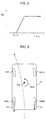
- a braking is applied to the front right wheel 10FR as shown in Fig. 8.
- a braking force being applied to the front right wheel 10FR, a clockwise turning moment is generated in the vehicle around the braked front right wheel 10FR by the inertia force of the vehicle concentrated at the center of gravity Og of the vehicle, thereby generating an equivalent clockwise yaw moment Mas around the center of gravity Og, acting against the spinning movement of the vehicle.
- a braking is applied to the front left wheel FL.
- Fig. 7 is a map showing an example of the relationship between the magnitude of the yaw rate deviation
Landscapes
- Engineering & Computer Science (AREA)
- Transportation (AREA)
- Mechanical Engineering (AREA)
- Regulating Braking Force (AREA)
- Steering Control In Accordance With Driving Conditions (AREA)
- Navigation (AREA)
- Control Of Driving Devices And Active Controlling Of Vehicle (AREA)
- Control Of Vehicle Engines Or Engines For Specific Uses (AREA)
- Hydraulic Control Valves For Brake Systems (AREA)
Applications Claiming Priority (3)
| Application Number | Priority Date | Filing Date | Title |
|---|---|---|---|
| JP21264797A JP3198993B2 (ja) | 1997-07-23 | 1997-07-23 | 車輌の挙動制御装置 |
| JP21264797 | 1997-07-23 | ||
| JP212647/97 | 1997-07-23 |
Publications (3)
| Publication Number | Publication Date |
|---|---|
| EP0893320A2 true EP0893320A2 (fr) | 1999-01-27 |
| EP0893320A3 EP0893320A3 (fr) | 2000-04-05 |
| EP0893320B1 EP0893320B1 (fr) | 2003-10-01 |
Family
ID=16626102
Family Applications (1)
| Application Number | Title | Priority Date | Filing Date |
|---|---|---|---|
| EP98112189A Expired - Lifetime EP0893320B1 (fr) | 1997-07-23 | 1998-07-01 | Appareil de régulation du comportement d'un véhicule ayant des moyens pour empêcher une régulation erronée due à un décalage du point milieu d'un capteur de couple de lacet |
Country Status (4)
| Country | Link |
|---|---|
| US (1) | US6363309B1 (fr) |
| EP (1) | EP0893320B1 (fr) |
| JP (1) | JP3198993B2 (fr) |
| DE (1) | DE69818573T2 (fr) |
Cited By (5)
| Publication number | Priority date | Publication date | Assignee | Title |
|---|---|---|---|---|
| WO2000053472A1 (fr) | 1999-03-11 | 2000-09-14 | Lucas Varity Gmbh | Systeme de regulation de la stabilite du vehicule |
| EP1172283A1 (fr) | 2000-07-13 | 2002-01-16 | Polyrim | Dispositif de fixation réglable pour pièces en matière plastique, notamment pour garde-boue et ailerons de véhicules |
| EP1388473A1 (fr) * | 2002-08-05 | 2004-02-11 | Ford Global Technologies, LLC | Procédé et système de correction du décalage de capteurs |
| GB2412100A (en) * | 2004-03-18 | 2005-09-21 | Ford Global Tech Llc | Brake-steering a vehicle |
| WO2007121720A1 (fr) * | 2006-04-25 | 2007-11-01 | Adc Automotive Distance Control Systems Gmbh | Procédé de calibrage d'une mesure de la vitesse de lacet |
Families Citing this family (35)
| Publication number | Priority date | Publication date | Assignee | Title |
|---|---|---|---|---|
| US6834218B2 (en) * | 2001-11-05 | 2004-12-21 | Ford Global Technologies, Llc | Roll over stability control for an automotive vehicle |
| US6356188B1 (en) | 2000-09-25 | 2002-03-12 | Ford Global Technologies, Inc. | Wheel lift identification for an automotive vehicle |
| US6654674B2 (en) * | 2001-11-21 | 2003-11-25 | Ford Global Technologies, Llc | Enhanced system for yaw stability control system to include roll stability control function |
| US20040024505A1 (en) * | 2002-08-05 | 2004-02-05 | Salib Albert Chenouda | System and method for operating a rollover control system in a transition to a rollover condition |
| US20040024504A1 (en) * | 2002-08-05 | 2004-02-05 | Salib Albert Chenouda | System and method for operating a rollover control system during an elevated condition |
| US7239949B2 (en) * | 2003-02-26 | 2007-07-03 | Ford Global Technologies, Llc | Integrated sensing system |
| US20050206231A1 (en) * | 2004-03-18 | 2005-09-22 | Ford Global Technologies, Llc | Method and apparatus for controlling an automotive vehicle using brake-steer and normal load adjustment |
| US7165644B2 (en) * | 2004-03-18 | 2007-01-23 | Ford Global Technologies, Llc | Method and apparatus of controlling an automotive vehicle using brake-steer as a function of steering wheel torque |
| US8380416B2 (en) * | 2004-03-18 | 2013-02-19 | Ford Global Technologies | Method and apparatus for controlling brake-steer in an automotive vehicle in reverse |
| US7502675B2 (en) * | 2004-04-01 | 2009-03-10 | Delphi Technologies, Inc. | Feedforward control of motor vehicle roll angle |
| US7451032B2 (en) * | 2004-06-02 | 2008-11-11 | Ford Global Technologies, Llc | System and method for determining desired yaw rate and lateral velocity for use in a vehicle dynamic control system |
| JP4094597B2 (ja) * | 2004-09-22 | 2008-06-04 | 本田技研工業株式会社 | 操舵装置 |
| US7191047B2 (en) * | 2004-09-27 | 2007-03-13 | Delphi Technologies, Inc. | Motor vehicle control using a dynamic feedforward approach |
| US7640081B2 (en) * | 2004-10-01 | 2009-12-29 | Ford Global Technologies, Llc | Roll stability control using four-wheel drive |
| US7715965B2 (en) | 2004-10-15 | 2010-05-11 | Ford Global Technologies | System and method for qualitatively determining vehicle loading conditions |
| US7668645B2 (en) | 2004-10-15 | 2010-02-23 | Ford Global Technologies | System and method for dynamically determining vehicle loading and vertical loading distance for use in a vehicle dynamic control system |
| US7660654B2 (en) | 2004-12-13 | 2010-02-09 | Ford Global Technologies, Llc | System for dynamically determining vehicle rear/trunk loading for use in a vehicle control system |
| US7480547B2 (en) | 2005-04-14 | 2009-01-20 | Ford Global Technologies, Llc | Attitude sensing system for an automotive vehicle relative to the road |
| US7590481B2 (en) * | 2005-09-19 | 2009-09-15 | Ford Global Technologies, Llc | Integrated vehicle control system using dynamically determined vehicle conditions |
| US8121758B2 (en) * | 2005-11-09 | 2012-02-21 | Ford Global Technologies | System for determining torque and tire forces using integrated sensing system |
| US7600826B2 (en) * | 2005-11-09 | 2009-10-13 | Ford Global Technologies, Llc | System for dynamically determining axle loadings of a moving vehicle using integrated sensing system and its application in vehicle dynamics controls |
| JP4839888B2 (ja) * | 2006-02-27 | 2011-12-21 | トヨタ自動車株式会社 | 車両の挙動制御装置 |
| JP2007278982A (ja) * | 2006-04-11 | 2007-10-25 | Toyota Motor Corp | 車両挙動制御装置 |
| KR101090914B1 (ko) * | 2006-04-25 | 2011-12-08 | 주식회사 만도 | 차량 안정성 제어시스템의 엔진제어방법 |
| JP4415994B2 (ja) * | 2007-02-01 | 2010-02-17 | トヨタ自動車株式会社 | ヨー角速度推定装置 |
| JP5007207B2 (ja) * | 2007-11-15 | 2012-08-22 | クラリオン株式会社 | ナビゲーション装置および角速度検出信号補正値算出方法 |
| US8195357B2 (en) * | 2008-04-16 | 2012-06-05 | GM Global Technology Operations LLC | In-vehicle sensor-based calibration algorithm for yaw rate sensor calibration |
| DE102009006472B4 (de) * | 2009-01-28 | 2019-06-13 | Dr. Ing. H.C. F. Porsche Aktiengesellschaft | Kraftfahrzeug |
| JP4928582B2 (ja) * | 2009-05-08 | 2012-05-09 | 本田技研工業株式会社 | 車両挙動センサの中点補正方法 |
| JP4713653B2 (ja) * | 2009-04-23 | 2011-06-29 | 本田技研工業株式会社 | 電動パワーステアリング装置 |
| JP4871370B2 (ja) * | 2009-04-23 | 2012-02-08 | 本田技研工業株式会社 | 車両挙動センサの中点学習方法と車両挙動検出システム |
| KR101309508B1 (ko) * | 2011-10-10 | 2013-09-24 | 주식회사 만도 | 차량의 차선 변경 보조 시스템 및 그 방법 |
| KR101415208B1 (ko) * | 2011-10-14 | 2014-08-07 | 주식회사 만도 | 차량 제어 장치 및 방법 |
| JP6481660B2 (ja) * | 2016-06-09 | 2019-03-13 | トヨタ自動車株式会社 | 車両用挙動制御装置 |
| WO2019016942A1 (fr) * | 2017-07-21 | 2019-01-24 | 三菱電機株式会社 | Dispositif d'aide à la conduite, serveur, et procédé d'aide à la conduite |
Citations (1)
| Publication number | Priority date | Publication date | Assignee | Title |
|---|---|---|---|---|
| JPH06115418A (ja) | 1992-10-02 | 1994-04-26 | Toyota Motor Corp | 駆動・制動力配分制御装置 |
Family Cites Families (21)
| Publication number | Priority date | Publication date | Assignee | Title |
|---|---|---|---|---|
| DE3731756A1 (de) | 1987-09-22 | 1989-03-30 | Bosch Gmbh Robert | Verfahren zur regelung der fahrstabilitaet eines fahrzeugs |
| DE3912045A1 (de) | 1989-04-12 | 1990-10-25 | Bayerische Motoren Werke Ag | Verfahren zur regelung einer querdynamischen zustandsgroesse eines kraftfahrzeuges |
| JP2552380B2 (ja) | 1990-05-14 | 1996-11-13 | 日産自動車株式会社 | 検出値オフセット量除去装置 |
| JP2762711B2 (ja) * | 1990-07-02 | 1998-06-04 | 日産自動車株式会社 | 車両の制動挙動補償装置 |
| JP2829354B2 (ja) | 1990-07-18 | 1998-11-25 | マツダ株式会社 | 車両制御装置 |
| US5826204A (en) * | 1993-11-30 | 1998-10-20 | Siemens Aktiengesellschaft | Circuit configuration for evaluation of the signals from a yaw rate sensor |
| DE69506741T2 (de) * | 1994-01-14 | 1999-09-02 | Matsushita Electric Industrial Co. | Vorrichtung zum Steuern eines Lenkwinkels |
| EP0751888B1 (fr) * | 1994-03-25 | 1998-05-27 | Siemens Aktiengesellschaft | Circuit d'evaluation des signaux d'un capteur de vitesse de lacet |
| JP3268124B2 (ja) * | 1994-06-27 | 2002-03-25 | 富士重工業株式会社 | 車両のトルク配分制御装置 |
| DE19502858C1 (de) | 1995-01-30 | 1996-07-11 | Siemens Ag | Verfahren und Schaltungsanordnung zum Kompensieren der Signalfehler eines Giergeschwindigkeitssensors |
| JP2993400B2 (ja) * | 1995-06-09 | 1999-12-20 | 三菱自動車工業株式会社 | 車両の旋回制御装置 |
| US5915800A (en) * | 1995-06-19 | 1999-06-29 | Fuji Jukogyo Kabushiki Kaisha | System for controlling braking of an automotive vehicle |
| US5869753A (en) * | 1995-08-25 | 1999-02-09 | Honda Giken Kogyo Kabushiki Kaisha | System for estimating the road surface friction |
| JP3577372B2 (ja) * | 1995-09-11 | 2004-10-13 | 富士重工業株式会社 | 制動力制御装置 |
| JP3132371B2 (ja) * | 1995-10-06 | 2001-02-05 | トヨタ自動車株式会社 | 車輌の挙動制御装置 |
| JP3248414B2 (ja) * | 1995-10-18 | 2002-01-21 | トヨタ自動車株式会社 | 車輌の挙動制御装置 |
| US5899952A (en) * | 1995-12-27 | 1999-05-04 | Toyota Jidosha Kabushiki Kaisha | Device for estimating slip angle of vehicle body through interrelation thereof with yaw rate |
| US5857160A (en) * | 1996-05-23 | 1999-01-05 | General Motors Corporation | Sensor-responsive control method and apparatus |
| US5667286A (en) * | 1996-05-29 | 1997-09-16 | General Motors Corporation | Brake control system |
| US5720533A (en) * | 1996-10-15 | 1998-02-24 | General Motors Corporation | Brake control system |
| US5746486A (en) * | 1996-10-16 | 1998-05-05 | General Motors Corporation | Brake control system |
-
1997
- 1997-07-23 JP JP21264797A patent/JP3198993B2/ja not_active Expired - Lifetime
-
1998
- 1998-06-16 US US09/098,419 patent/US6363309B1/en not_active Expired - Lifetime
- 1998-07-01 EP EP98112189A patent/EP0893320B1/fr not_active Expired - Lifetime
- 1998-07-01 DE DE69818573T patent/DE69818573T2/de not_active Expired - Lifetime
Patent Citations (1)
| Publication number | Priority date | Publication date | Assignee | Title |
|---|---|---|---|---|
| JPH06115418A (ja) | 1992-10-02 | 1994-04-26 | Toyota Motor Corp | 駆動・制動力配分制御装置 |
Cited By (9)
| Publication number | Priority date | Publication date | Assignee | Title |
|---|---|---|---|---|
| WO2000053472A1 (fr) | 1999-03-11 | 2000-09-14 | Lucas Varity Gmbh | Systeme de regulation de la stabilite du vehicule |
| DE19910868A1 (de) * | 1999-03-11 | 2000-09-21 | Varity Gmbh | Fahrzeugstabilitätsregelsystem |
| US6718279B2 (en) | 1999-03-11 | 2004-04-06 | Lucas Varity Gmbh | Vehicle stability regulating system |
| EP1172283A1 (fr) | 2000-07-13 | 2002-01-16 | Polyrim | Dispositif de fixation réglable pour pièces en matière plastique, notamment pour garde-boue et ailerons de véhicules |
| EP1388473A1 (fr) * | 2002-08-05 | 2004-02-11 | Ford Global Technologies, LLC | Procédé et système de correction du décalage de capteurs |
| GB2412100A (en) * | 2004-03-18 | 2005-09-21 | Ford Global Tech Llc | Brake-steering a vehicle |
| GB2412100B (en) * | 2004-03-18 | 2007-08-08 | Ford Global Tech Llc | A method for brake-steering a vehicle |
| WO2007121720A1 (fr) * | 2006-04-25 | 2007-11-01 | Adc Automotive Distance Control Systems Gmbh | Procédé de calibrage d'une mesure de la vitesse de lacet |
| US7684945B2 (en) | 2006-04-25 | 2010-03-23 | Adc Automotive Distance Control Systems Gmbh | Method for the calibration of a yaw rate measurement |
Also Published As
| Publication number | Publication date |
|---|---|
| EP0893320B1 (fr) | 2003-10-01 |
| JPH1134701A (ja) | 1999-02-09 |
| US6363309B1 (en) | 2002-03-26 |
| DE69818573D1 (de) | 2003-11-06 |
| DE69818573T2 (de) | 2004-08-05 |
| EP0893320A3 (fr) | 2000-04-05 |
| JP3198993B2 (ja) | 2001-08-13 |
Similar Documents
| Publication | Publication Date | Title |
|---|---|---|
| EP0893320B1 (fr) | Appareil de régulation du comportement d'un véhicule ayant des moyens pour empêcher une régulation erronée due à un décalage du point milieu d'un capteur de couple de lacet | |
| US6101434A (en) | Behavior control device of vehicle based upon double checking of yaw rate deviation | |
| EP3659878B1 (fr) | Appareil de détection de perturbation de véhicule | |
| JP3695164B2 (ja) | 車輌の挙動制御方法 | |
| EP1495931B1 (fr) | Dispositif de contrôle du comportement d'un véhicule | |
| KR100642023B1 (ko) | 차량의 거동 제어장치 | |
| US7562948B2 (en) | Deceleration control apparatus and method for automotive vehicle | |
| EP2433840B1 (fr) | Unité de commande de mouvement pour un véhicule en fonction d'informations sur la variation d'accélération | |
| EP2181026B1 (fr) | Appareil conçu pour commander le comportement d'un véhicule | |
| JP2001171504A (ja) | 路面摩擦係数推定装置 | |
| JP2800141B2 (ja) | 車輪の目標滑りに対する実際滑りの偏差に関係して制動圧力を制御する方法 | |
| EP1375281B1 (fr) | Dispositif d'estimation de la caractéristique de virage d'un véhicule automobile | |
| US7775608B2 (en) | Method for controlling a brake pressure | |
| JP2006034012A (ja) | 車輪のスリップ率演算方法及び車輪の制駆動力制御方法 | |
| JP2008537707A (ja) | 車両の姿勢安定制御方法及びその装置 | |
| EP0416480A2 (fr) | Commande de direction des roues arrière pour véhicule | |
| US12060050B2 (en) | Braking control device for vehicle | |
| JP6787027B2 (ja) | 車両の走行制御装置 | |
| EP1577147B1 (fr) | Système et procédé de commande de décéleration pour un véhicule | |
| KR100477410B1 (ko) | 차량의 제동력 제어식 거동 제어 장치 및 방법 | |
| JP4228837B2 (ja) | 車輪速度推定装置、車体速度推定装置、および車両挙動制御装置 | |
| JP2004155303A (ja) | 車輌用制動力制御装置 | |
| JPH10324260A (ja) | 車両の舵角制御装置 | |
| JP2002173012A (ja) | 車輌の挙動制御装置 | |
| US20050029862A1 (en) | Vehicle motion control apparatus |
Legal Events
| Date | Code | Title | Description |
|---|---|---|---|
| PUAI | Public reference made under article 153(3) epc to a published international application that has entered the european phase |
Free format text: ORIGINAL CODE: 0009012 |
|
| AK | Designated contracting states |
Kind code of ref document: A2 Designated state(s): DE FR GB |
|
| AX | Request for extension of the european patent |
Free format text: AL;LT;LV;MK;RO;SI |
|
| PUAL | Search report despatched |
Free format text: ORIGINAL CODE: 0009013 |
|
| AK | Designated contracting states |
Kind code of ref document: A3 Designated state(s): AT BE CH CY DE DK ES FI FR GB GR IE IT LI LU MC NL PT SE |
|
| AX | Request for extension of the european patent |
Free format text: AL;LT;LV;MK;RO;SI |
|
| 17P | Request for examination filed |
Effective date: 20000517 |
|
| AKX | Designation fees paid |
Free format text: DE FR GB |
|
| GRAH | Despatch of communication of intention to grant a patent |
Free format text: ORIGINAL CODE: EPIDOS IGRA |
|
| GRAS | Grant fee paid |
Free format text: ORIGINAL CODE: EPIDOSNIGR3 |
|
| GRAL | Information related to payment of fee for publishing/printing deleted |
Free format text: ORIGINAL CODE: EPIDOSDIGR3 |
|
| GRAS | Grant fee paid |
Free format text: ORIGINAL CODE: EPIDOSNIGR3 |
|
| GRAA | (expected) grant |
Free format text: ORIGINAL CODE: 0009210 |
|
| AK | Designated contracting states |
Kind code of ref document: B1 Designated state(s): DE FR GB |
|
| REG | Reference to a national code |
Ref country code: GB Ref legal event code: FG4D |
|
| REF | Corresponds to: |
Ref document number: 69818573 Country of ref document: DE Date of ref document: 20031106 Kind code of ref document: P |
|
| ET | Fr: translation filed | ||
| PLBE | No opposition filed within time limit |
Free format text: ORIGINAL CODE: 0009261 |
|
| STAA | Information on the status of an ep patent application or granted ep patent |
Free format text: STATUS: NO OPPOSITION FILED WITHIN TIME LIMIT |
|
| 26N | No opposition filed |
Effective date: 20040702 |
|
| REG | Reference to a national code |
Ref country code: GB Ref legal event code: 746 Effective date: 20130412 |
|
| REG | Reference to a national code |
Ref country code: DE Ref legal event code: R084 Ref document number: 69818573 Country of ref document: DE Effective date: 20130410 |
|
| REG | Reference to a national code |
Ref country code: FR Ref legal event code: PLFP Year of fee payment: 19 |
|
| REG | Reference to a national code |
Ref country code: FR Ref legal event code: PLFP Year of fee payment: 20 |
|
| PGFP | Annual fee paid to national office [announced via postgrant information from national office to epo] |
Ref country code: FR Payment date: 20170613 Year of fee payment: 20 Ref country code: GB Payment date: 20170628 Year of fee payment: 20 |
|
| PGFP | Annual fee paid to national office [announced via postgrant information from national office to epo] |
Ref country code: DE Payment date: 20170627 Year of fee payment: 20 |
|
| REG | Reference to a national code |
Ref country code: DE Ref legal event code: R071 Ref document number: 69818573 Country of ref document: DE |
|
| REG | Reference to a national code |
Ref country code: GB Ref legal event code: PE20 Expiry date: 20180630 |
|
| PG25 | Lapsed in a contracting state [announced via postgrant information from national office to epo] |
Ref country code: GB Free format text: LAPSE BECAUSE OF EXPIRATION OF PROTECTION Effective date: 20180630 |