EP0893346A1 - Dispositif de serrage de bande pour un appareil de cerclage - Google Patents
Dispositif de serrage de bande pour un appareil de cerclage Download PDFInfo
- Publication number
- EP0893346A1 EP0893346A1 EP98112520A EP98112520A EP0893346A1 EP 0893346 A1 EP0893346 A1 EP 0893346A1 EP 98112520 A EP98112520 A EP 98112520A EP 98112520 A EP98112520 A EP 98112520A EP 0893346 A1 EP0893346 A1 EP 0893346A1
- Authority
- EP
- European Patent Office
- Prior art keywords
- roller
- band
- machine
- tensioning roller
- deflector
- Prior art date
- Legal status (The legal status is an assumption and is not a legal conclusion. Google has not performed a legal analysis and makes no representation as to the accuracy of the status listed.)
- Granted
Links
Images


Classifications
-
- B—PERFORMING OPERATIONS; TRANSPORTING
- B65—CONVEYING; PACKING; STORING; HANDLING THIN OR FILAMENTARY MATERIAL
- B65B—MACHINES, APPARATUS OR DEVICES FOR, OR METHODS OF, PACKAGING ARTICLES OR MATERIALS; UNPACKING
- B65B13/00—Bundling articles
- B65B13/18—Details of, or auxiliary devices used in, bundling machines or bundling tools
- B65B13/22—Means for controlling tension of binding means
Definitions
- Such machines are known for example from DE 195 16 043. At such strapping machines is a plastic band through the belt conveyor at high speed into the tape guide to form the loop shot the package. The end of the tape is held by a tape holder caught and committed. Then the drive of the belt conveyor reversed so that the loop fits tightly around the circumference of the package. Well now the tensioning roller of the tensioning device, its peripheral surface in a certain Angular range is wrapped by the belt, driven so that on the belt a resilience is exerted. The loop is in this tensioned state by means of a locking device, usually an ultrasonic welding device or friction welding device, closed.
- a locking device usually an ultrasonic welding device or friction welding device, closed.
- the object of the invention is to provide a strapping machine which is inexpensive and can be used reliably and exerting a high tension on the strap loop to be closed.
- the tension roller on it Circumferential surface is provided with a friction surface and that at least one deflector is provided which is movable between the belt and the friction surface of the tension roller and whose contact surface for the band is designed as a smooth sliding surface.
- the peripheral surface of the tensioning roller as a friction surface, it is possible, the coefficient of friction between the plastic belt and the tension pulley to increase. In this way, a very high tension can be transferred to the belt.
- the size of the clamping force is apart from the coefficient of friction between the belt and Tensioner also from the wrap angle, i.e. the angular section at which the tape rests against the tensioning roller as well as from the pressure device generated pressing force, depending.
- the friction surface can be made of a rubber-like coating, for example Vulkollan (registered trademark of Bayer).
- the friction surface preferably consists of the metal peripheral surface of the Tensioner pulley, into which pyramid-shaped projections are milled with tips are. In this way, the friction surface forms by penetrating the tips Plastic strap forms a positive connection with the strap, thus ensuring production high tension due to the tension pulley.
- the deflector can during the fast belt drive when shooting and when Retraction can be introduced, then the tape alone over the smooth sliding surface of the deflector slides and has no contact with the friction surface of the tension pulley.
- the tape can over the angular range of the tension pulley that of the plastic belt is wrapped, three steel pegs are arranged between the tape and the tension pulley can be pushed.
- the deflector is preferably designed as a section of a cylinder jacket that over the angular range of the tension pulley wrapped around the plastic band can be moved.
- the cylinder-shaped deflectors on a rotatably mounted coaxial to the tension pulley Cover plate attached, which is driven by a rotary drive.
- the cover plate extends the dimensions of the tensioner pulley arrangement only slightly in the axial direction Direction.
- the cylinder-shaped deflector also causes only a slight Increase in tensioner roller dimensions in the radial direction.
- the invention can be realized with a minimal space requirement, so that the machine according to the invention can be made compact.
- the band preferably wraps around an angular section of the tensioning roller of approximately 90 °, the deflector encompassing an angular section of at least the same size.
- a stop element is provided which is a complete in a locked position Pressing the pressure roller against the tension roller prevented, so that a gap remains formed between the surfaces of the two rollers.
- the unimpeded pressing against each other of the peripheral surfaces of tensioning roller and pressure roller to ensure the optimal Tension is achieved. It is especially the case with rolls with a structured surface necessary that the surfaces are pressed against each other so far that their Interlocking the projections with each other and in between the roller surfaces tape can penetrate.
- a controller is preferably provided which moves the stop into the locked position spends the absence of the tape when using a tape capture device is determined between the pressure roller and the tension roller.
- a simple switch off the pressure drive of the pressure roller can not be realized because All drives of the machine, i.e. also the pressure drive, must be operable even when the machine is open without an inserted band.
- the Function of the individual machine components is activated by activating the individual Drives checked with separate drive switches when the machine is open. In order to when checking and activating the pressure drive, the collision of the Avoid surfaces of the pressure roller and the tension roller with missing tape the stop described must be provided.
- the stop described is preferably integrated into the cover plate, which carries the deflector.
- the cover plate has one to form the stop enlarged diameter and has in the area where no stop is provided (release position), a reduced diameter.
- a contact surface that is rigid with the Pressure roller is connected.
- the contact surface is from the outer Peripheral surface of an annular flange arranged coaxially to the pressure roller, which lies in the same plane as the cover plate of the tension pulley.
- the strapping machine 1 shown in FIG. 1 corresponds to the state of the Technology DE 195 16 043 A1 and is used for strapping packages 28 with a Volume 2, which is drawn off by a feed device 4 from a supply roll 3 and a tape magazine 5 is fed. From there, the belt is transported by means of a belt conveyor 6, which consists of two opposing drive rollers 7,8 exists, through a tensioning device 9 through a tape guide in one Tape guide frame 10 fed so that the tape as a loop around the Pack 28 puts around. The tape end is from a tape holder, not shown gripped, and then the drive of the belt conveyor 6 reverses, so that the tape loop is pulled out of the tape guide frame 10 is and fits tightly against the package 28.
- the clamping device 9 activated which a tension roller 11 and a pressable against the tension roller 11 Pressure roller 12 includes.
- the pressure roller 12 presses the band 2 firmly against the Tension roller 11, the tension roller 11 being driven in the retracting direction, so that the band loop with a predetermined high tension force around the package 28 is pulled around.
- the closing device 13 consists in the Rule from an ultrasonic or friction welding device, which loop start and loop end welded together.
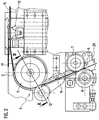
- the tensioning device 9 is shown enlarged in FIGS. 2 and 3. It consists of a large tension roller 11 and a small pressure roller 12, which can be pressed against the tensioning roller 11 via a swivel lever 14. As well in the peripheral surface of the tension roller 11 as well as in the peripheral surface of the pressure roller 12 are mutually orthogonal, substantially V-shaped grooves milled so that there are small, pyramid-like bodies with a square base and sharp point. The friction surfaces structured in this way are preferred hardened by plasma nitriding and enable high transmission Tensile forces on the belt 2.
- the belt 2 wraps around the tension roller 11 - from the Belt conveyor 6 starting - in an angular section of more than 90 ° and then runs past the closing device 13 to the band channel 15.
- the clamping device 9 is shown during the clamping operation, in which the band 2 is clamped between the tension roller 11 and the pressure roller 12 and due to the drive of the tensioning device 9 closely around the looped Package 28 is pulled.
- the pressure roller 12 is a not shown Drive device firmly pressed against the tension roller 11, so that the tape 2nd is clamped between the circumferential surfaces of both rollers 11, 12.
- a cover plate 16 is arranged opposite its end face, which a Deflector 17 in the form of a cylindrical section.
- a Deflector 17 in the form of a cylindrical section.
- the cover plate 16 is not shown in Fig. 2, so that the view of the behind Cover disc extending band 2 and the deflector 17 is released. Since in Fig. 2 and 3 the band 2 is shown in the tensioned state, i.e. between the peripheral surfaces the tension roller 11 and the pressure roller 12 is clamped, is the Deflector 17 on the right side facing away from the pressure roller 12.
- Fig. 3 shows that the tension roller 11 with a guide plate 18 and a Gear 19 arranged on a common motor-driven hollow shaft 20 and with the guide disk 18 and gear 19 by means of connecting screws 21 is screwed.
- the gear 19 meshes with one also with an external toothing 22 provided section of the pressure roller 12, and the guide disk 18th engages in a complementary groove 23 of the pressure roller 12 between the friction surface and the section with the external toothing 22.
- the line of engagement of the external teeth 22 and the Zabnrades 19 connected to the tensioning roller 11 lies in the Circumferential surface of the tension roller 11, so that the drive acting on the hollow shaft 20 (not shown) acts on the pressure roller 12 via the toothing in such a way that this without slipping to that between this pressure roller 12 and the tension roller 11 pinched band 2 is moved.
- the cover plate 16 is rotatably mounted to the hollow shaft 20 and thus of the Tensioner roller drive decoupled. It is arranged on a inside the hollow shaft 20, separately driven shaft 24 attached.
- the shaft 24 is normal Machine operation driven in such a way that the cover plate 16 with the deflector 17th from the already described clamping position shown in FIGS. 2, 3 and 4 in the shot position shown in Fig. 5 and moved back.
- the shot position is the deflector 17 by about 180 ° in the circumferential direction to the clamping position offsets and essentially covers the angular range of the tensioning pulley 11, which the band 2 wraps around.
- the tape 2 now slides over as completely smooth Slide surface formed surface of the deflector 17.
- the pressure roller 12 is at the shot and during the rapid retraction pivoted away from the tension roller 11, so that no contact between the Band 2 and the surface of the pressure roller 12 formed as a friction surface.
- FIG. 6 shows a further position of the cover plate 16, which is used for maintenance work and generally in the absence of a belt between idler 11 and Pressure roller 12 is set. It can be seen that in this position the Pressure roller 12 not with its outer circumference against the outer circumference of the Tension roller 11 is present.
- the outer diameter of the cover disk is 16 the tension roller 11 enlarged in the entire circumferential area so that a distance between the peripheral surface of the pressure roller 12 and the nearest surface of the Tension roller 11 is observed.
- the intervention of the Ring flange 25 in the flat recess 30 of the tension pulley a certain distance between the two friction surfaces of tension roller 11 and pressure roller 12.
- the entry position Fig. 5
- the Cover disc 16 has the Cover disc 16 to its maximum diameter, the band 2 over the Sliding surface of the deflector 17 slides and a little play between the belt and the friction surface of the pressure roller 12 remains.
- a deep recess 27 is finally provided in one position the ring flange 25 protrudes in the clamping position, so that the outer surfaces of the Tension roller 11 and the pressure roller 12 can be pressed against each other.
Landscapes
- Engineering & Computer Science (AREA)
- Mechanical Engineering (AREA)
- Basic Packing Technique (AREA)
Applications Claiming Priority (2)
| Application Number | Priority Date | Filing Date | Title |
|---|---|---|---|
| DE19730449 | 1997-07-16 | ||
| DE19730449A DE19730449A1 (de) | 1997-07-16 | 1997-07-16 | Spannvorrichtung für Umreifungsmaschinen |
Publications (2)
| Publication Number | Publication Date |
|---|---|
| EP0893346A1 true EP0893346A1 (fr) | 1999-01-27 |
| EP0893346B1 EP0893346B1 (fr) | 2001-03-07 |
Family
ID=7835869
Family Applications (1)
| Application Number | Title | Priority Date | Filing Date |
|---|---|---|---|
| EP98112520A Expired - Lifetime EP0893346B1 (fr) | 1997-07-16 | 1998-07-07 | Dispositif de serrage de bande pour un appareil de cerclage |
Country Status (5)
| Country | Link |
|---|---|
| US (1) | US6032440A (fr) |
| EP (1) | EP0893346B1 (fr) |
| AT (1) | ATE199522T1 (fr) |
| DE (2) | DE19730449A1 (fr) |
| ES (1) | ES2156423T3 (fr) |
Cited By (1)
| Publication number | Priority date | Publication date | Assignee | Title |
|---|---|---|---|---|
| WO2013007157A1 (fr) * | 2011-07-13 | 2013-01-17 | Chien-Fa Lai | Mécanisme d'alimentation et de marche arrière pour machine de cerclage |
Families Citing this family (9)
| Publication number | Priority date | Publication date | Assignee | Title |
|---|---|---|---|---|
| US20060144563A1 (en) * | 2003-02-19 | 2006-07-06 | Ludwig Hellenthal | Plasmatized heat exchanger |
| US6981353B2 (en) * | 2003-06-20 | 2006-01-03 | Illinois Tool Works, Inc. | Strapping machine with strap feeding and tensioning system with automatic refeed |
| DE102004027730A1 (de) * | 2004-05-07 | 2006-02-23 | Georg Lang | Vorrichtung zur Umreifung eines Packguts |
| US7240612B1 (en) * | 2006-05-03 | 2007-07-10 | Illinois Tool Works Inc. | Strapping machine |
| US11999516B2 (en) | 2008-04-23 | 2024-06-04 | Signode Industrial Group Llc | Strapping device |
| US10518914B2 (en) | 2008-04-23 | 2019-12-31 | Signode Industrial Group Llc | Strapping device |
| DE102011075629B4 (de) * | 2011-05-11 | 2016-09-15 | Smb Schwede Maschinenbau Gmbh | Verfahren zur Ansteuerung der Bandantriebseinrichtung einer Umreifungsmaschine sowie entsprechende Umreifungsmaschine |
| PL3105127T3 (pl) | 2014-02-10 | 2019-11-29 | Orgapack Gmbh | Urządzenie do spinania taśmą |
| DE102016108696A1 (de) | 2016-05-11 | 2017-11-16 | Mosca Gmbh | Verfahren zur Umreifung von Gegenständen, wiederverschließbares Gebinde und Verbindungselement |
Citations (3)
| Publication number | Priority date | Publication date | Assignee | Title |
|---|---|---|---|---|
| GB2206867A (en) * | 1987-07-08 | 1989-01-18 | Strapack Corp | Band loading apparatus in a packaging machine |
| EP0337782A1 (fr) * | 1988-04-15 | 1989-10-18 | Signode Kabushiki Kaisha | Dispositif à cercler à l'aide d'un ruban |
| US5379576A (en) * | 1992-06-10 | 1995-01-10 | Strapack Corporation | Band feeding and tightening apparatus for packing machine |
Family Cites Families (9)
| Publication number | Priority date | Publication date | Assignee | Title |
|---|---|---|---|---|
| US4218969A (en) * | 1979-02-01 | 1980-08-26 | Nichiro Kogyo Company, Limited | Band feeding and tightening apparatus for strapping machine |
| DE2906756A1 (de) * | 1979-02-21 | 1980-09-04 | Nichiro Kogyo Kk | Verfahren und vorrichtung zum zufuehren und spannen eines spannbandes |
| DE3249559A1 (de) * | 1982-05-29 | 1985-08-14 | Hoesch Ag, 4600 Dortmund | Vorschub- und spannvorrichtung fuer ein um ein packstueck zu spannendes umreifungsband |
| CH662791A5 (de) * | 1984-03-13 | 1987-10-30 | Konrad Feinmechanik Ag A | Maschine zum anlegen eines bandes um ein packgut. |
| US4683017A (en) * | 1985-11-25 | 1987-07-28 | Signode Corporation | Method and apparatus for forming a loop with end-gripped strap |
| US5024149A (en) * | 1989-04-15 | 1991-06-18 | Signode Corporation | Binding strap operating apparatus |
| JPH0747284Y2 (ja) * | 1991-10-01 | 1995-11-01 | 昌弘機工株式会社 | 自動梱包機 |
| US5459977A (en) * | 1993-12-09 | 1995-10-24 | Illinois Tool Works Inc. | Method and apparatus for an improved power strapping machine |
| DE19516043A1 (de) * | 1995-05-04 | 1996-11-07 | Mosca G Maschf | Maschine zum Umschnüren |
-
1997
- 1997-07-16 DE DE19730449A patent/DE19730449A1/de not_active Withdrawn
-
1998
- 1998-07-07 AT AT98112520T patent/ATE199522T1/de not_active IP Right Cessation
- 1998-07-07 ES ES98112520T patent/ES2156423T3/es not_active Expired - Lifetime
- 1998-07-07 DE DE59800507T patent/DE59800507D1/de not_active Expired - Fee Related
- 1998-07-07 EP EP98112520A patent/EP0893346B1/fr not_active Expired - Lifetime
- 1998-07-16 US US09/116,842 patent/US6032440A/en not_active Expired - Fee Related
Patent Citations (3)
| Publication number | Priority date | Publication date | Assignee | Title |
|---|---|---|---|---|
| GB2206867A (en) * | 1987-07-08 | 1989-01-18 | Strapack Corp | Band loading apparatus in a packaging machine |
| EP0337782A1 (fr) * | 1988-04-15 | 1989-10-18 | Signode Kabushiki Kaisha | Dispositif à cercler à l'aide d'un ruban |
| US5379576A (en) * | 1992-06-10 | 1995-01-10 | Strapack Corporation | Band feeding and tightening apparatus for packing machine |
Cited By (2)
| Publication number | Priority date | Publication date | Assignee | Title |
|---|---|---|---|---|
| WO2013007157A1 (fr) * | 2011-07-13 | 2013-01-17 | Chien-Fa Lai | Mécanisme d'alimentation et de marche arrière pour machine de cerclage |
| TWI468321B (zh) * | 2011-07-13 | 2015-01-11 | Packyway Inc | 捆包機送退帶機構 |
Also Published As
| Publication number | Publication date |
|---|---|
| US6032440A (en) | 2000-03-07 |
| ATE199522T1 (de) | 2001-03-15 |
| ES2156423T3 (es) | 2001-06-16 |
| DE59800507D1 (de) | 2001-04-12 |
| DE19730449A1 (de) | 1999-01-21 |
| EP0893346B1 (fr) | 2001-03-07 |
Similar Documents
| Publication | Publication Date | Title |
|---|---|---|
| EP0664256B1 (fr) | Outil de tension et de fermeture pour encercler un objet avec une bande thermoplastique | |
| DE102005031735B3 (de) | Spannratsche zum Spannen und Halten von Spannmitteln | |
| DE102008060323B4 (de) | Haspel | |
| DE68921490T2 (de) | Zusammensetzung für eine gurtzange. | |
| EP2338796B1 (fr) | Dispositif d'entraînement de bande pour une machine de cerclage | |
| EP0893346B1 (fr) | Dispositif de serrage de bande pour un appareil de cerclage | |
| EP0064734A1 (fr) | Dispositif pour appliquer et tendre une bande de serrage autour d'un emballage | |
| DE60317998T2 (de) | Vorrichtung zum Umreifen mit verbesserter Spanntrommel | |
| EP1159197A1 (fr) | Dispositif pour tendre et fermer des bandes de cerclage | |
| EP0581020A1 (fr) | Dispositif pour tendre au moins une bandelette profilée encerclant au moins un corps tubulaire | |
| EP0930997B1 (fr) | Outil pour la fixation d'un cable | |
| EP0600320A1 (fr) | Dispositif de tirage pour matériaux allongés | |
| DE3249559A1 (de) | Vorschub- und spannvorrichtung fuer ein um ein packstueck zu spannendes umreifungsband | |
| DE3400177C2 (fr) | ||
| EP0529446A1 (fr) | Dispositif pour fixer et tendre un blanchet sur un cylindre d'une machine à imprimer | |
| DE3025008A1 (de) | Abzugsvorrichtung fuer flachstrickmaschinen | |
| DE3812626C2 (fr) | ||
| EP1799457B1 (fr) | Dispositif comportant plusieurs rouleaux | |
| EP0422427B1 (fr) | Dispositif de tension pour lien d'emballage | |
| DE29723441U1 (de) | Lastgetriebe für Motorantriebe an Stufenschaltern o.dgl. | |
| EP0618111A1 (fr) | Tendeur de ceinture pour système de ceinture de sécurité pour véhicule | |
| DE2657664A1 (de) | Kupplung fuer riemenantriebe | |
| DE19701049C1 (de) | Radialwalzkopf | |
| EP0847922B1 (fr) | Dispositif de cerclage de paquets | |
| DE19907066A1 (de) | Bandspann-Vorrichtung an einer Umreifungsmaschine |
Legal Events
| Date | Code | Title | Description |
|---|---|---|---|
| PUAI | Public reference made under article 153(3) epc to a published international application that has entered the european phase |
Free format text: ORIGINAL CODE: 0009012 |
|
| AK | Designated contracting states |
Kind code of ref document: A1 Designated state(s): AT CH DE ES FR GB IT LI NL SE |
|
| AX | Request for extension of the european patent |
Free format text: AL;LT;LV;MK;RO;SI |
|
| 17P | Request for examination filed |
Effective date: 19990223 |
|
| AKX | Designation fees paid |
Free format text: AT CH DE ES FR GB IT LI NL SE |
|
| GRAG | Despatch of communication of intention to grant |
Free format text: ORIGINAL CODE: EPIDOS AGRA |
|
| 17Q | First examination report despatched |
Effective date: 20000606 |
|
| GRAG | Despatch of communication of intention to grant |
Free format text: ORIGINAL CODE: EPIDOS AGRA |
|
| GRAH | Despatch of communication of intention to grant a patent |
Free format text: ORIGINAL CODE: EPIDOS IGRA |
|
| GRAH | Despatch of communication of intention to grant a patent |
Free format text: ORIGINAL CODE: EPIDOS IGRA |
|
| GRAA | (expected) grant |
Free format text: ORIGINAL CODE: 0009210 |
|
| RIN1 | Information on inventor provided before grant (corrected) |
Inventor name: LUEDTKE, PETER |
|
| AK | Designated contracting states |
Kind code of ref document: B1 Designated state(s): AT CH DE ES FR GB IT LI NL SE |
|
| REF | Corresponds to: |
Ref document number: 199522 Country of ref document: AT Date of ref document: 20010315 Kind code of ref document: T |
|
| REG | Reference to a national code |
Ref country code: CH Ref legal event code: EP |
|
| REF | Corresponds to: |
Ref document number: 59800507 Country of ref document: DE Date of ref document: 20010412 |
|
| ITF | It: translation for a ep patent filed | ||
| REG | Reference to a national code |
Ref country code: CH Ref legal event code: NV Representative=s name: BUGNION S.A. |
|
| ET | Fr: translation filed | ||
| REG | Reference to a national code |
Ref country code: ES Ref legal event code: FG2A Ref document number: 2156423 Country of ref document: ES Kind code of ref document: T3 |
|
| GBT | Gb: translation of ep patent filed (gb section 77(6)(a)/1977) |
Effective date: 20010607 |
|
| REG | Reference to a national code |
Ref country code: GB Ref legal event code: IF02 |
|
| PLBE | No opposition filed within time limit |
Free format text: ORIGINAL CODE: 0009261 |
|
| STAA | Information on the status of an ep patent application or granted ep patent |
Free format text: STATUS: NO OPPOSITION FILED WITHIN TIME LIMIT |
|
| 26N | No opposition filed | ||
| PGFP | Annual fee paid to national office [announced via postgrant information from national office to epo] |
Ref country code: ES Payment date: 20080723 Year of fee payment: 11 Ref country code: DE Payment date: 20080910 Year of fee payment: 11 Ref country code: CH Payment date: 20080724 Year of fee payment: 11 |
|
| PGFP | Annual fee paid to national office [announced via postgrant information from national office to epo] |
Ref country code: NL Payment date: 20080722 Year of fee payment: 11 Ref country code: IT Payment date: 20080726 Year of fee payment: 11 Ref country code: FR Payment date: 20080718 Year of fee payment: 11 Ref country code: AT Payment date: 20080722 Year of fee payment: 11 |
|
| PGFP | Annual fee paid to national office [announced via postgrant information from national office to epo] |
Ref country code: GB Payment date: 20080723 Year of fee payment: 11 |
|
| PGFP | Annual fee paid to national office [announced via postgrant information from national office to epo] |
Ref country code: SE Payment date: 20080724 Year of fee payment: 11 |
|
| REG | Reference to a national code |
Ref country code: CH Ref legal event code: PL |
|
| EUG | Se: european patent has lapsed | ||
| GBPC | Gb: european patent ceased through non-payment of renewal fee |
Effective date: 20090707 |
|
| NLV4 | Nl: lapsed or anulled due to non-payment of the annual fee |
Effective date: 20100201 |
|
| REG | Reference to a national code |
Ref country code: FR Ref legal event code: ST Effective date: 20100331 |
|
| PG25 | Lapsed in a contracting state [announced via postgrant information from national office to epo] |
Ref country code: LI Free format text: LAPSE BECAUSE OF NON-PAYMENT OF DUE FEES Effective date: 20090731 Ref country code: FR Free format text: LAPSE BECAUSE OF NON-PAYMENT OF DUE FEES Effective date: 20090731 Ref country code: CH Free format text: LAPSE BECAUSE OF NON-PAYMENT OF DUE FEES Effective date: 20090731 |
|
| PG25 | Lapsed in a contracting state [announced via postgrant information from national office to epo] |
Ref country code: GB Free format text: LAPSE BECAUSE OF NON-PAYMENT OF DUE FEES Effective date: 20090707 |
|
| PG25 | Lapsed in a contracting state [announced via postgrant information from national office to epo] |
Ref country code: DE Free format text: LAPSE BECAUSE OF NON-PAYMENT OF DUE FEES Effective date: 20100202 Ref country code: AT Free format text: LAPSE BECAUSE OF NON-PAYMENT OF DUE FEES Effective date: 20090707 |
|
| REG | Reference to a national code |
Ref country code: ES Ref legal event code: FD2A Effective date: 20090708 |
|
| PG25 | Lapsed in a contracting state [announced via postgrant information from national office to epo] |
Ref country code: ES Free format text: LAPSE BECAUSE OF NON-PAYMENT OF DUE FEES Effective date: 20090708 |
|
| PG25 | Lapsed in a contracting state [announced via postgrant information from national office to epo] |
Ref country code: IT Free format text: LAPSE BECAUSE OF NON-PAYMENT OF DUE FEES Effective date: 20090707 |
|
| PG25 | Lapsed in a contracting state [announced via postgrant information from national office to epo] |
Ref country code: SE Free format text: LAPSE BECAUSE OF NON-PAYMENT OF DUE FEES Effective date: 20090708 |
|
| PG25 | Lapsed in a contracting state [announced via postgrant information from national office to epo] |
Ref country code: NL Free format text: LAPSE BECAUSE OF NON-PAYMENT OF DUE FEES Effective date: 20100201 |