EP0893366A2 - Device for transporting vehicles, especially for estate cars, small vehicles or similar - Google Patents
Device for transporting vehicles, especially for estate cars, small vehicles or similar Download PDFInfo
- Publication number
- EP0893366A2 EP0893366A2 EP98113029A EP98113029A EP0893366A2 EP 0893366 A2 EP0893366 A2 EP 0893366A2 EP 98113029 A EP98113029 A EP 98113029A EP 98113029 A EP98113029 A EP 98113029A EP 0893366 A2 EP0893366 A2 EP 0893366A2
- Authority
- EP
- European Patent Office
- Prior art keywords
- floor
- vehicles
- stacking columns
- flap
- folded
- Prior art date
- Legal status (The legal status is an assumption and is not a legal conclusion. Google has not performed a legal analysis and makes no representation as to the accuracy of the status listed.)
- Granted
Links
Images



Classifications
-
- B—PERFORMING OPERATIONS; TRANSPORTING
- B65—CONVEYING; PACKING; STORING; HANDLING THIN OR FILAMENTARY MATERIAL
- B65D—CONTAINERS FOR STORAGE OR TRANSPORT OF ARTICLES OR MATERIALS, e.g. BAGS, BARRELS, BOTTLES, BOXES, CANS, CARTONS, CRATES, DRUMS, JARS, TANKS, HOPPERS, FORWARDING CONTAINERS; ACCESSORIES, CLOSURES, OR FITTINGS THEREFOR; PACKAGING ELEMENTS; PACKAGES
- B65D88/00—Large containers
- B65D88/02—Large containers rigid
- B65D88/12—Large containers rigid specially adapted for transport
- B65D88/122—Large containers rigid specially adapted for transport with access from above
- B65D88/123—Large containers rigid specially adapted for transport with access from above open top
-
- B—PERFORMING OPERATIONS; TRANSPORTING
- B65—CONVEYING; PACKING; STORING; HANDLING THIN OR FILAMENTARY MATERIAL
- B65D—CONTAINERS FOR STORAGE OR TRANSPORT OF ARTICLES OR MATERIALS, e.g. BAGS, BARRELS, BOTTLES, BOXES, CANS, CARTONS, CRATES, DRUMS, JARS, TANKS, HOPPERS, FORWARDING CONTAINERS; ACCESSORIES, CLOSURES, OR FITTINGS THEREFOR; PACKAGING ELEMENTS; PACKAGES
- B65D88/00—Large containers
- B65D88/02—Large containers rigid
- B65D88/12—Large containers rigid specially adapted for transport
- B65D88/127—Large containers rigid specially adapted for transport open-sided container, i.e. having substantially the whole side free to provide access, with or without closures
-
- B—PERFORMING OPERATIONS; TRANSPORTING
- B65—CONVEYING; PACKING; STORING; HANDLING THIN OR FILAMENTARY MATERIAL
- B65D—CONTAINERS FOR STORAGE OR TRANSPORT OF ARTICLES OR MATERIALS, e.g. BAGS, BARRELS, BOTTLES, BOXES, CANS, CARTONS, CRATES, DRUMS, JARS, TANKS, HOPPERS, FORWARDING CONTAINERS; ACCESSORIES, CLOSURES, OR FITTINGS THEREFOR; PACKAGING ELEMENTS; PACKAGES
- B65D88/00—Large containers
- B65D88/02—Large containers rigid
- B65D88/12—Large containers rigid specially adapted for transport
- B65D88/129—Transporter frames for containers
-
- B—PERFORMING OPERATIONS; TRANSPORTING
- B65—CONVEYING; PACKING; STORING; HANDLING THIN OR FILAMENTARY MATERIAL
- B65D—CONTAINERS FOR STORAGE OR TRANSPORT OF ARTICLES OR MATERIALS, e.g. BAGS, BARRELS, BOTTLES, BOXES, CANS, CARTONS, CRATES, DRUMS, JARS, TANKS, HOPPERS, FORWARDING CONTAINERS; ACCESSORIES, CLOSURES, OR FITTINGS THEREFOR; PACKAGING ELEMENTS; PACKAGES
- B65D88/00—Large containers
- B65D88/54—Large containers characterised by means facilitating filling or emptying
- B65D88/542—Ramps forming part of the container
-
- B—PERFORMING OPERATIONS; TRANSPORTING
- B65—CONVEYING; PACKING; STORING; HANDLING THIN OR FILAMENTARY MATERIAL
- B65D—CONTAINERS FOR STORAGE OR TRANSPORT OF ARTICLES OR MATERIALS, e.g. BAGS, BARRELS, BOTTLES, BOXES, CANS, CARTONS, CRATES, DRUMS, JARS, TANKS, HOPPERS, FORWARDING CONTAINERS; ACCESSORIES, CLOSURES, OR FITTINGS THEREFOR; PACKAGING ELEMENTS; PACKAGES
- B65D2585/00—Containers, packaging elements or packages specially adapted for particular articles or materials
- B65D2585/68—Containers, packaging elements or packages specially adapted for particular articles or materials for machines, engines, or vehicles in assembled or dismantled form
- B65D2585/6802—Containers, packaging elements or packages specially adapted for particular articles or materials for machines, engines, or vehicles in assembled or dismantled form specific machines, engines or vehicles
- B65D2585/686—Containers, packaging elements or packages specially adapted for particular articles or materials for machines, engines, or vehicles in assembled or dismantled form specific machines, engines or vehicles vehicles
- B65D2585/6867—Containers, packaging elements or packages specially adapted for particular articles or materials for machines, engines, or vehicles in assembled or dismantled form specific machines, engines or vehicles vehicles automobiles
Definitions
- the invention relates to a device for transporting vehicles, especially passenger cars, vans or the like, according to the preamble of claim 1, 6, 12 and / or 18.
- the known transport cage-like devices have a relatively high weight and show deficiencies in their Handling on. Also driving on the known Devices with the vehicles to be transported in multiple Proven problematic.
- the object of the invention is Devices (transport cages) for the transport of vehicles, in particular motor vehicles, vans or the like to create a low with sufficient stability
- Devices transport cages for the transport of vehicles, in particular motor vehicles, vans or the like to create a low with sufficient stability
- a device for solving this problem has the features of claim 1.
- the upright, transverse to the level of the floor trending walls have a relatively large resistance moment so that the weight of the walls is less than that Material to be saved to stiffen the floor.
- the hands or hand sections are preferably pivotable with longitudinal or transverse edges, in particular longitudinal edges, of the floor connected. In this way it is possible to cover the walls to pivot empty devices against the floor surface, thereby several devices are stacked to save space stack it. In addition, by pivoting the Walls or wall sections of the devices from the side fully or partially freely accessible, which opens doors to the the device driven vehicles to enter or exit the Allow driver to open fully and risk of damage of the doors due to a collision with parts of the device excluded are.
- the hand sections can be moved with the corresponding ones Edges of the ground. That’s it possible, individual, namely currently disturbing, wall sections push away.
- the wall sections keep their vertical position to the level of the ground, thereby reinforcing the Basically even with wall sections pushed away remains.
- both the long and the front sides of the Assign hands or hand sections to the floor. At least have the longitudinal side edges of the floor over side walls or Sidewall parts. The end faces of the floor then remain open, whereby the device can be used by vehicles at any time can.
- Another device for solving the basis of the invention Task which is also a cheerfulness of the device having the features described above can act, has the features of claim 6.
- the floor can therefore be extended. This gives the device in the longitudinal direction or direction of travel of the vehicles greater absorption capacity. In this way it is possible Devices usually, namely in the unextended state, correspond to the grid dimension of 40 'containers, where the space available allows for a pitch of 45 ' Enlarge containers. It is also extendable of the floor possible to enlarge the device so that such a number of longer vehicles can be stowed, which corresponds to the number of vehicles of shorter length.
- the device is preferably extended in such a way that at least one front edge of the floor is a ramp-like Flap is assigned, which can be designed as a hand.
- the ramp-like flap enables the device to be driven on without additional ramps. If the or each flap for transportation folded up, it serves as a front protection for yourself vehicles located on the floor of the device.
- the or each ramp be in several parts to train.
- the individual parts of the ramp are preferably connected by a pivot axis that is parallel to the corresponding end edge of the floor runs on the turn the entire ramp can be swiveled by a further swivel axis is articulated.
- the respective ramp can be folded in this way. This allows the ramp to be partially extended by using a Part of the ramp that is pivotally connected directly to the floor is swung down into the plane of the floor during the other, unneeded part of the ramp is folded up for Stabilization of the device and for simultaneous Front protection of the vehicles on it.
- the or each ramp or parts thereof in the folded up position State to connect with neighboring stacking columns.
- the longitudinal central axis of the bottom is provided, at least one Lane on at least one side with a guide or the like to provide.
- a guide or the like By driving along the guide the respective vehicle in an off-center position the floor, which has a slight entry and exit on one side of the vehicle Exit possible.
- the stands preferably Lane extending over the entire length of the floor opposite the level of the ground.
- the or each guide is preferably at a distance from the longitudinal central axis of the soil changeable.
- the leadership can thereby the respective width of that provided for loading the device Vehicle adjusted so that one side of the vehicle is located close to a longitudinal slope of the floor. On the other side of the vehicle is thus a maximum possible Distance to the corresponding side of the floor is available, which makes the best possible use of the remaining space becomes.
- the guide is firmly attached to the floor connect.
- the leadership takes over one. static stabilization of the floor, which means that it does not add anything to the device Gives weight; rather contributes to weight optimization.
- the device according to claim 18 provides for the floor To provide anchoring openings when the stacking columns are folded down lie free.
- Stacking columns can add these anchoring openings serve, by coupling pieces, for example twistlocks, a Connection to corresponding anchoring openings on the Manufacture underside of the respective stacking column and thereby the respective stacking column in the folded up position lock.
- the devices are empty, they are folded down on the floor Stacking columns form the anchoring openings thus exposed on the floor means for connecting the device with hoists, for example spreaders.
- Anchoring openings on the floor serve several devices, especially empty devices to connect suitable coupling pieces or the like.
- the device shown here is used to transport from the 1, 3 and 8 motor vehicles shown in particular Trucks, railway wagons, inland or sea ships.
- 2 shows 10 loaded devices on board with motor vehicles of an inland waterway vessel 11.
- the devices shown here are used as transport cages Recording of two motor vehicles 10 each.
- the unextended version shown in FIG. 1 corresponds to the external dimensions each device approximately the outer dimension of one 40 'containers.
- the transport cage type devices are together with the motor vehicles thereon 10 like Container can be handled.
- the loaded devices can be together with the motor vehicles 10 thereon such as containers one above the other and side by side on board the inland waterway vessel 11 to be stowed.
- On trucks or railroad cars are preferred two transport cages with motor vehicles on them 10 transported stacked one above the other.
- the devices are collapsible when unloaded, so that a larger number of stacked transport cage-like Devices can be transported to save space can.
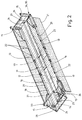
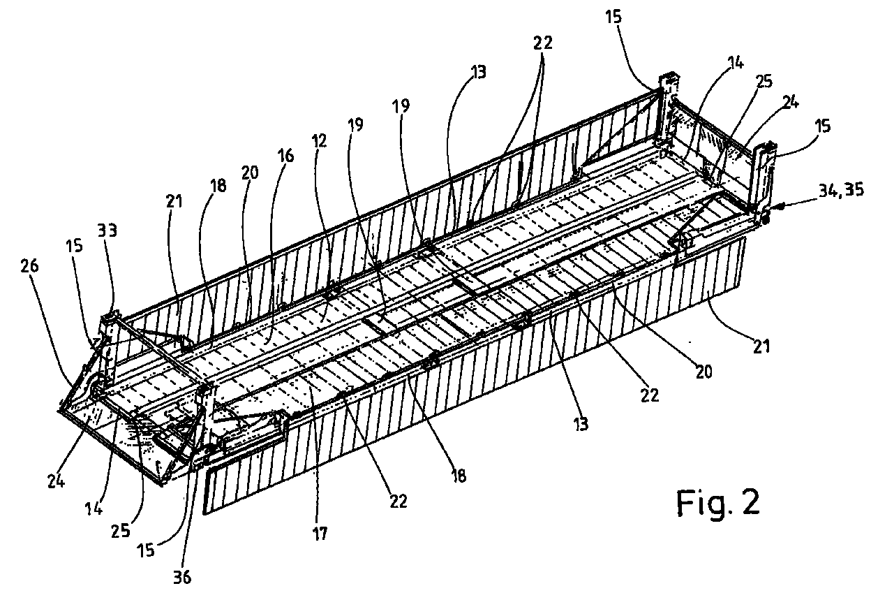
- Each transport cage-like device has a rectangular top Base 12 with two parallel longitudinal side edges 13 and two parallel (shorter) transverse edges 14 as well as giftable ones Stacking columns 15.
- the floor 12 is constructed like a frame, has namely, along the longitudinal side edges 13 Side members 18 and cross members 14 running along the transverse edges 19. The of the side members 18 and the cross members 19th enclosed area can with additional stiffening beams, not shown be provided.
- On the one made by the bearers There are two frames in the longitudinal direction of the floor 12 running parallel lanes 16 and 17 for those on the Devices to accommodate devices 10.
- Each of the four corner points of the rectangular bottom 12 is a stacking column 15 assigned. The stacking columns are in the transport position 15 folded up, so run perpendicular to the approximately horizontal Bottom 12.
- Pivot axis 20 is each stacking column 15 against the corresponding one Longitudinal edge 13 pivotable.
- each longitudinal side edge 13 of the Bottom 12 is associated with a side wall 21.
- Each of the same trained over the entire length of the device between two stacking columns 15 arranged on the same side Side wall 21 is pivotable on the corresponding Longitudinal edge 13 of the bottom 12 articulated. To this end serve several at a distance on the longitudinal side edge 13 of the bottom 12 distributed hinges 22.
- folded up State (left representation of Fig. 2) are vertical front edges 23 of the corresponding side wall 21 with the associated Stacking columns 15 can be connected by means of corresponding bars.
- the respective side wall 21 is folded up Locked position and at the same time a stable connection of the respective side wall 20 with the opposite end edges 23 of the same associated stacking columns 15 are produced. Consequently forms each side wall 21 with the two associated with it Stacking columns 15 and the hinges 22 with the corresponding Longitudinal edge 13 of the bottom 12 one unit.
- the side walls 21 contribute to stabilization of the bottom 12, in particular by the Side walls 21 with the bottom 12 hinges 22.
- Die Sidewalls 21 form when folded up (left illustration 2) a lateral protection for the on the transport cage-like Device for motor vehicles 10.
- the side walls 21 expose the long sides of the device, whereby the motor vehicles 10 on the device from the side are accessible here, especially the doors of the Motor vehicles 10 for getting in and out of drivers almost let it open completely.
- An alternative embodiment of the device not shown has side walls with one as in the embodiment 2 foldable on the longitudinal side edges 13 of the floor 12 hinged frame.
- side wall part forming sliding doors arranged to each other can be moved that the loaded device frame-like side wall is completely closed.
- Sliding doors are moved that in the corresponding area only the side wall frame remains. Through the open The inner surface of the same can then be opened doors of the Swing vehicle through, making it easy for a driver to get out of his Vehicle can get in or out.
- each side wall from load-bearing or load-bearing side wall parts provides for each side wall from load-bearing or load-bearing side wall parts to form the slidably on the longitudinal side edges 13 of the bottom 12 are arranged.
- This displaceability of the side wall parts takes place in the same way as for example in sliding door wardrobes is known.
- the leadership of the sliding and resilient or load-bearing side wall parts on the respective longitudinal side edge 13 of the base 12 stored. This is a positive and non-positive Storage that makes it possible to exercise on the floor 12 To transfer loads to the sliding side wall parts, whereby these intercept possible deflections of the floor 12 or reduce.
- the device according to FIG. 2 also has its Cross edges 14 over hands, namely transverse walls, which act as flaps 24 are trained.
- the flaps 24 are preferably of the Motor vehicles 10 passable.
- Each flap 24 is via a hinge 25 or possibly Several hinges can also be folded around a horizontal swivel axis connected to the respective transverse edge of the bottom 12.
- the Flap 24 thus forms a ramp for driving one behind the other arranged devices.
- the respective forms Flap 24 but also an extension of the bottom 12 of the Device, making the device with longer motor vehicles 10 can be loaded, if necessary during the Transport with rear or front wheels stop on the flap 24 can.
- the stability of the flap 24 required for this in the extended, horizontal position is achieved by retractable struts 26 of two hinged together Arms poor. With the flap swung into the horizontal position 24 (left representation of FIG. 2) the lever arms reach Strut 26 in an extended position, creating a reliable Securing the position of the respective flap 24 in the bottom 12 extending horizontal position is guaranteed.
- the device is loaded with vehicles that only cover the area of the floor 12 can take up after loading the flaps 24 are pivoted up into a transport position (Right representation of Fig. 2).
- the superscript Flaps 24 form end walls of the device in the transport position, which on the one hand serve to protect the vehicles on the front or rear from the outside and on the other hand the Stabilize the device.
- the swung up Flaps 24 by positive locking elements associated with the opposite sides of the flaps 24 Stacking columns 15 form-fitting (but detachable) connectable. This creates a stabilizing connection between the Flaps 24, the bottom 12 and those associated with the flaps 24 Stacking columns 15.
- the device receives has a relatively high torsional stiffness an open box-shaped receptacle for the motor vehicles 10th
- each two-part Flap 27 is with a corresponding hinge, not shown Cross edge 14 of the base 12 with an inner part 28 pivoted. With the inner part 28 is in turn Hinges, not shown, pivot an outer part 29 of the Flap 27 hinged. Inner part 28 and outer part 29 thus form the two parts of each flap 27. In the extended position of the Flap 27 are both the inner part 28 and that Outer part 29 approximately in the plane of the bottom 12 (FIGS. 5 and 9).
- the respective flap 27 serves as an up and down ramp for the motor vehicles 10.
- both the inner parts 28 and the outer parts 29 horizontal extensions opposite sides of the floor 12
- the flap 24 is extended on both sides Bottom 12 dimensions, which correspond approximately to a 45 'container.
- the stacking columns 15 are located on grid points, which correspond to those of a 40 'container.
- the stacking columns 15 are of the same design and each have over an elongated, box-like shape.
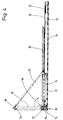
- a lower one The end of each stacking column 15 is pivotable with the respective one Corner of the floor 12 connected by a horizontal and parallel pivot axis 30 extending to the transverse edge 14 the stacking columns 15 in a perpendicular to the respective longitudinal side edge 13 of the floor 12 extending plane pivotable (Fig. 4).
- Starting from each corner of floor 12 is one along a part of the corresponding longitudinal side edge 13 extending Recess 31 provided which corresponds to the Dimensions of a stacking column 15 are formed.
- the Recesses 31 are used in a horizontal Most of the position of the folded down stacking columns 15. In this way, the tops of the folded up protrude Stacking columns 15 not significantly above the top of the Bottom 12 out (Fig. 4).
- each stacking column 15 has one Brace 32 lockable against the floor 12.
- Each one The strut 32 assigned to the stacking column 15 is vertical with a strut extending to the respective longitudinal side edge of the bottom 12 Level arranged.
- One end of each strut 32 is pivotable the respective long side edge 13 of the bottom 12 articulated.
- the opposite end of each strut 32 is with the corresponding one folded up stack column 15 connectable (Fig. 4).
- Stacking columns 15 are the struts 32 around the articulated Articulation point on the floor 12 pivotable against the floor 12 (Fig. 4).
- each stacking column 15 is with a stacked column 15 in Arranged parallel to the floor 12 horizontal levels Provide plates, each with an anchoring opening 33 and 34 is arranged.
- the corner points of the floor 12 two parallel, horizontal plates are also assigned, in each of which there is an anchoring opening 35, 36.
- the plates with the anchoring openings 35, 36 can by commercially available container corner fittings are formed. Then are also in the upright front and side edges of the Bottom 12 anchoring openings.
- each stacking column 15 34 corresponds to that on the top of the bottom 12 arranged anchoring opening 35 such that both Anchoring openings 34 and 35 through a commercially available coupling piece, for example a twistlock 37, form-fitting with each other can be connected.
- a commercially available coupling piece for example a twistlock 37
- the pivot axis 30 for connection each stacking column 15 with the bottom 12 is placed so that at folded down stacking columns 15, the upper anchoring opening 35 exposed on floor 12. This anchoring opening 35 is therefore freely accessible for connecting several on top of each other stacked empty device with folded stacking columns 15 or also for coupling hoists.
- the anchoring opening 33 at the top of each stacking column 15 preferably also serves to receive a coupling piece, for example a twistlock 38 (Fig. 4).
- the Twistlocks 38 then serve to connect two stacked devices, by inserting the top of the into the anchor hole 33 Twistlocks inserted at the top of each stacking column 15 38 into the anchoring opening 36 on the underside of the floor 12 a device placed on the lower device intervenes.
- each stacking column 15 directly with a coupling piece to connect, preferably permanently. Then it can the anchoring openings 33 and 34 at the top and bottom the stacking columns 15 are omitted.
- the permanent on top and Bottom of each stacking column 15 attached coupling pieces can used when necessary to stack one on top of the other Devices with upright, folded-out stacking columns 15 to connect with each other and around the folded up in transport position To lock stacking columns 15 in this position ⁇ by the permanent on the undersides of the stacking columns 15 attached coupling pieces with the anchoring openings 35 the top of the bottom 12 are connected.
- the device Roads 16 and 17 with different distances from the longitudinal central axis 39 of the device or the bottom 12 provided.
- the The embodiment shown (Fig. 3) has the right lane 17 a greater distance from the longitudinal central axis 39 than the left lane 16.
- the motor vehicles 10 drive off-center on the floor 12 of the device.
- the passenger side close to the long side edge 13, while the driver side one clear distance to the opposite longitudinal side edge 13 having. This distance is especially important if the Device with the side walls 21 not shown in FIG. 3 is provided. Then you can even when closed Side walls 21, the driver's door are opened so far that the Drivers of motor vehicles 19 relatively easy on and can get out.
- an elongated guide 42 is provided.
- This guide 42 is in the embodiment shown on the outside of a Lane (in Fig. 2 the left lane 16) arranged.
- the Guide 42 is firmly connected to the floor 12 here.
- a vertical one Action 43 of the guide 42 is next to the corresponding one Lane 16 and provides a guide here left tire 44 of the respective motor vehicle 10.
- the guide 42 or the wall 43 practically have the effect of curbs.
Landscapes
- Engineering & Computer Science (AREA)
- Mechanical Engineering (AREA)
- Handcart (AREA)
- Loading Or Unloading Of Vehicles (AREA)
- Tents Or Canopies (AREA)
Abstract
Der Transport von Fahrzeugen vom Hersteller zum Kunden erfordert insbesondere dann, wenn es sich um einen überseeischen Transport handelt, ein mehrfaches Umladen der Fahrzeuge. Dazu mußten die Fahrzeuge bislang mehrfach umgefahren werden. Um das zu vermeiden werden transportkäfigartige Vorrichtungen verwendet, die nach dem Prinzip von Containern mit den Fahrzeugen umgeschlagen werden können. Bekannte Vorrichtungen dieser Art verfügen über ein relativ hohes Gewicht und sind auch problematisch zu handhaben.The transportation of vehicles from the manufacturer to the customer requires especially if it is overseas Transport acts, a multiple reloading of the vehicles. To So far, the vehicles had to be driven around several times. To do that to avoid transport cage-like devices are used, which handled the principle of containers with the vehicles can be. Known devices of this type have a relatively high weight and are also problematic to handle.
Die erfindungsgemäße Vorrichtung verfügt über lastaufnehmende
Seitenwände (21), die schwenkbar oder verschiebbar mit dem Boden
(12) der Vorrichtung verbunden sind. Die Seitenwände (21)
stabilisieren den Boden (12), wodurch die gesamte Vorrichtung
leichter als herkömmliche Vorrichtungen dieser Art ausgebildet
sein können. Darüber hinaus ermöglicht das Herunterschwenken
bzw. Verschieben der Seitenwände (21) den freien Zugang der
Seiten der Kraftfahrzeuge. Dadurch wird vor allem das Ein- und
Austeigen von Fahrern erleichtert und es werden Beschädigungen
der Türen und sonstiger Teile der Kraftfahrzeuge (10) vermieden.
Description
Die Erfindung betrifft eine Vorrichtung zum Transport von Fahrzeugen,
insbesondere Personenkraftwagen, Kleintransportern oder
dergleichen, gemäß dem Oberbegriff des Anspruchs 1, 6, 12
und/oder 18.The invention relates to a device for transporting vehicles,
especially passenger cars, vans or
the like, according to the preamble of
Der Transport von Fahrzeugen insbesondere von der Produktionsstätte zum Händler oder Kunden, erfolgt üblicherweise so, daß aus der Fabrik jedes Fahrzeug auf eine Halde gefahren wird. Von der Halde wird das Fahrzeug dann auf einen Eisenbahn- oder Straßentransporter gefahren. Sind Fahrzeuge über größere Distanzen zu transportieren, geschieht das insbesondere zwischen verschiedenen Kontinenten auf dem Seewege. Das macht zusätzlich ein mehrfaches Umfahren der Fahrzeuge erforderlich, die dann nämlich vom Transporter auf die Halde, von dort aufs Schiff und nach dem Schiffstransport in umgekehrter Weise zu verfahren sind. Außerdem müssen die Fahrzeuge auf den verschiedenen Transportern gelascht werden. Das alles ist nicht nur Zeit- und arbeitsaufwendig; bei jedem Umfahren besteht auch die Gefahr der Beschädigung des jeweiligen Fahrzeugs.The transportation of vehicles in particular from the production site to the dealer or customer, is usually done in such a way that every vehicle is driven onto a heap from the factory. From the dump will then put the vehicle on a railroad or Road transporter driven. Are vehicles larger than that Transporting distances in particular happens between different continents by sea. That makes additional multiple driving around the vehicles required, which then from the transporter to the heap, from there to the Ship and after ship transportation in reverse are wrong. In addition, the vehicles on the different Transporters are lashed. It is not all Time and labor consuming; with every detour there is also Risk of damage to the respective vehicle.
Um die vorstehend geschilderte Transportweise von Fahrzeugen zu vereinfachen, ist es bereits bekannt, Vorrichtungen zu verwenden, die einen befahrbaren Boden und vorzugsweise Stapelsäulen aufweisen. Diese Vorrichtungen bilden so praktisch Transportkäfige, die sich gegebenenfalls übereinander stapeln lassen und womit die darauf befindlichen Fahrzeugen ähnlich wie Container umgeschlagen werden.In order to transport vehicles as described above simplify, it is already known to use devices which a drivable floor and preferably stacking columns exhibit. These devices practically form transport cages, which can be stacked on top of each other and with which the vehicles on it are similar to containers be handled.
Die bekannten transportkäfigartigen Vorrichtungen verfügen über ein relativ hohes Gewicht und weisen Uzulänglichkeiten bei ihrer Handhabung auf. Auch hat sich das Befahren der bekannten Vorrichtungen mit den zu transportierenden Fahrzeugen in mehrfacher Hinsicht als problematisch erwiesen.The known transport cage-like devices have a relatively high weight and show deficiencies in their Handling on. Also driving on the known Devices with the vehicles to be transported in multiple Proven problematic.
Hiervon ausgehend liegt der Erfindung die Aufgabe zugrunde, Vorrichtungen (Transportkäfige) zum Transport von Fahrzeugen, insbesondere Kraftfahrzeugen, Kleintransportern oder dergleichen zu schaffen, die bei ausreichender Stabilität ein geringes Gewicht aufweisen, leicht handhabbar und problemlos von den zu transportierenden Fahrzeugen befahrbar sind.Proceeding from this, the object of the invention is Devices (transport cages) for the transport of vehicles, in particular motor vehicles, vans or the like to create a low with sufficient stability Have weight, easy to handle and easy from the to transporting vehicles are passable.
Eine Vorrichtung zur Lösung dieser Aufgabe weist die Merkmale des Anspruchs 1 auf. Dadurch, daß dem die Fahrzeuge tragenden Boden lastaufnehmende Hände bzw. Handabschnitte zugeordnet sind, kann der Boden entsprechend geringer dimensioniert und somit leichter sein. Die aufrechten, quer zur Ebene des Bodens verlaufenden Wände weisen ein relativ großes Wiederstandsmoment auf, so daß das Gewicht der Wände geringer ist als das dadurch einzusparende Material zur Versteifung des Bodens.A device for solving this problem has the features of claim 1. The fact that the vehicles Floor load-bearing hands or hand sections assigned are, the floor can be dimensioned accordingly smaller and thus be easier. The upright, transverse to the level of the floor trending walls have a relatively large resistance moment so that the weight of the walls is less than that Material to be saved to stiffen the floor.
Die Hände bzw. Handabschnitte sind vorzugsweise verschwenkbar mit Längs- oder Querrändern, insbesondere Längsrändern, des Bodens verbunden. Auf diese Weise ist es möglich, die Wände bei leeren Vorrichtungen gegen die Bodenfläche zu schwenken, wodurch sich platzsparend mehrere Vorrichtungen übereinander stapeln lassen. Außerdem werden durch das Verschwenken der Wände bzw. Wandabschnitte die Vorrichtungen von der Seite her ganz oder teilweise frei zugänglich, wodurch sich Türen der auf die Vorrichtung gefahrenen Fahrzeuge zum Ein- oder Ausstieg der Fahrer vollständig öffnen lassen und die Gefahr einer Beschädigung der Türen durch eine Kollision mit Teilen der Vorrichtung ausgeschlossen sind.The hands or hand sections are preferably pivotable with longitudinal or transverse edges, in particular longitudinal edges, of the floor connected. In this way it is possible to cover the walls to pivot empty devices against the floor surface, thereby several devices are stacked to save space stack it. In addition, by pivoting the Walls or wall sections of the devices from the side fully or partially freely accessible, which opens doors to the the device driven vehicles to enter or exit the Allow driver to open fully and risk of damage of the doors due to a collision with parts of the device excluded are.
Alternativ können die Handabschnitte verschiebbar mit den entsprechenden Rändern des Bodens verbunden sein. Dadurch ist es möglich, einzelne, nämlich momentan störende, Wandabschnitte wegzuschieben. Die Wandabschnitte behalten ihre senkrechte Position zur Ebene des Bodens bei, wodurch die Verstärkung des Bodens auch bei weggeschobenen Wandabschnitten im wesentlichen bestehen bleibt.Alternatively, the hand sections can be moved with the corresponding ones Edges of the ground. That’s it possible, individual, namely currently disturbing, wall sections push away. The wall sections keep their vertical position to the level of the ground, thereby reinforcing the Basically even with wall sections pushed away remains.
Es ist auch denkbar, die Hände bzw. Handabschnitte mit Öffnungen oder zu öffnende Handteile zu versehen, wodurch die Hände stets den Boden stabilisieren, aber gleichwohl dort zu öffnen sind, wo zum Beispiel zum leichten Ein- und Ausstieg von Fahrern die Türen der Fahrzeuge geöffnet werden müssen.It is also conceivable to have the hands or hand sections with openings or to provide opening hand parts, which makes the hands always stabilize the floor, but still open there are where, for example, for easy entry and exit of drivers the doors of the vehicles must be opened.
Es ist denkbar, sowohl den Längs- als auch den Stirnseiten des Bodens Hände bzw. Handabschnitte zuzuordnen. Mindestens verfügen die Längsseitenränder des Bodens über Seitenwände oder Seitenwandteile. Die Stirnseiten des Bodens bleiben dann offen, wodurch die Vorrichtung jederzeit von Fahrzeugen befahren werden kann.It is conceivable both the long and the front sides of the Assign hands or hand sections to the floor. At least have the longitudinal side edges of the floor over side walls or Sidewall parts. The end faces of the floor then remain open, whereby the device can be used by vehicles at any time can.
Eine weitere Vorrichtung zur Lösung der der Erfindung zugrundeliegenden Aufgabe, bei der es sich auch um eine Heiterbildung der die vorstehend beschriebenen Merkmale aufweisenden Vorrichtung handeln kann, weist die Merkmale des Anspruchs 6 auf. Demnach ist der Boden verlängerbar. Dadurch erhält die Vorrichtung in Längsrichtung bzw. Fahrtrichtung der Fahrzeuge eine größere Aufnahmekapazität. Auf dieses Weise ist es möglich, Vorrichtungen die üblicherweise, nämlich im unverlängerten Zustand, dem Rastermaß von 40' Containern entsprechen, dort, wo es die Platzverhältnisse zulassen auf das Rastermaß von 45' Containern zu vergrößern. Außerdem ist es durch die Verlängerbarkeit des Bodens möglich, die Vorrichtung so zu vergrößern, daß eine solche Anzahl längerer Fahrzeuge gestaut werden kann, die der Anzahl von Fahrzeugen geringerer Länge entspricht.Another device for solving the basis of the invention Task, which is also a cheerfulness of the device having the features described above can act, has the features of claim 6. The floor can therefore be extended. This gives the device in the longitudinal direction or direction of travel of the vehicles greater absorption capacity. In this way it is possible Devices usually, namely in the unextended state, correspond to the grid dimension of 40 'containers, where the space available allows for a pitch of 45 ' Enlarge containers. It is also extendable of the floor possible to enlarge the device so that such a number of longer vehicles can be stowed, which corresponds to the number of vehicles of shorter length.
Die Verlängerung der Vorrichtung erfolgt vorzugsweise derart, daß mindestens einer Stirnkante des Bodens eine rampenartige Klappe zugeordnet ist, die als eine Hand ausgebildet sein kann. Die rampenartige Klappe ermöglicht das Befahren der Vorrichtung ohne zusätzliche Rampen. Wenn die oder jede Klappe zum Transport hochgeklappt ist, dient sie als Frontschutz für die sich auf dem Boden der Vorrichtung befindlichen Fahrzeuge.The device is preferably extended in such a way that at least one front edge of the floor is a ramp-like Flap is assigned, which can be designed as a hand. The ramp-like flap enables the device to be driven on without additional ramps. If the or each flap for transportation folded up, it serves as a front protection for yourself vehicles located on the floor of the device.
Weiterhin wird vorgeschlagen, die oder jede Rampe mehrteilig auszubilden. Vorzugsweise sind die einzelnen Teile der Rampe durch eine Schwenkachse miteinander verbunden, die parallel zur entsprechenden Stirnkante des Bodens verläuft, an der wiederum die gesamte Rampe schwenkbar, durch eine weitere Schwenkachse angelenkt ist. Die jeweilige Rampe ist auf diese Weise faltbar. Dadurch kann die Rampe teilweise verlängert werden, indem ein direkt mit dem Boden schwenkbar verbundenes Teil der Rampe etwa in die Ebene des Bodens heruntergeschwenkt ist, während der andere, nicht benötigte Teil der Rampe hochgeklappt wird zur Stabilisierung der Vorrichtung und zum gleichzeitigen Frontschutz der darauf sich befindlichen Fahrzeuge.It is also proposed that the or each ramp be in several parts to train. The individual parts of the ramp are preferably connected by a pivot axis that is parallel to the corresponding end edge of the floor runs on the turn the entire ramp can be swiveled by a further swivel axis is articulated. The respective ramp can be folded in this way. This allows the ramp to be partially extended by using a Part of the ramp that is pivotally connected directly to the floor is swung down into the plane of the floor during the other, unneeded part of the ramp is folded up for Stabilization of the device and for simultaneous Front protection of the vehicles on it.
Gemäß einer bevorzugten Weiterbildung der Vorrichtung ist vorgesehen, die oder jede Rampe bzw. Teile derselben in hochgeklapptem Zustand mit benachbarten Stapelsäulen zu verbinden. Dadurch erhält die Vorrichtung eine größere Stabilität, insbesondere wird die Querstabilität verbessert. Das führt insbesondere am Transport mehrerer übereinander gestapelter, beladener Vorrichtungen dazu, daß der so gebildete Stapel während des Transports eine ausreichende Stabilität aufweist, die wichtig ist, damit sich die Vorrichtung beim Transport nicht dauerhaft verformt und es zu keinen Beschädigungen der von der Vorrichtung aufgenommenen Fahrzeuge kommt.According to a preferred development of the device, the or each ramp or parts thereof in the folded up position State to connect with neighboring stacking columns. This gives the device greater stability, in particular the lateral stability is improved. That leads in particular on the transport of several stacked, loaded Devices so that the stack thus formed during the Transport has sufficient stability, which is important is so that the device is not permanent during transport deformed and there is no damage to the device recorded vehicles comes.
Eine weitere Lösung der der Erfindung zugrundeliegenden Aufgabe,
bei der es sich auch um eine Heiterentwicklung von Vorrichtungen
mit den vorstehend beschriebenen Merkmalen handeln
kann, weist die Merkmale des Anspruchs 12 auf. Dadurch, daß die
Fahrspuren auf dem Boden unterschiedliche Abstände zur
Längsmittelachse des Bodens haben, ist eine außermittige
Beladung der Vorrichtung möglich. Dadurch können die Fahrzeuge
mit einer Seite bis an den Rand des Bodens herangefahren werden,
wodurch auf der gegenüberliegenden Seite mehr Platz entsteht,
der ein leichteres Ein- und Aussteigen der Fahrer zuläßt,
indem die Türen sich zu diesem Zweck weiter öffnen lassen,
und zwar ohne daß die Gefahr der Beschädigung derselben
besteht.A further solution to the problem on which the invention is based,
which is also a cheerful development of devices
act with the features described above
can, has the features of
Zur Bildung unterschiedlicher Abstände der Fahrspuren zur Längsmittelachse des Bodens ist vorgesehen, mindestens eine Fahrspur auf wenigstens einer Seite mit einer Führung oder dergleichen zu versehen. Durch Entlangfahren an der Führung gelangt das jeweilige Fahrzeug in eine außermittige Position auf dem Boden, die an einer Fahrzeugseite einen leichten Ein- und Ausstieg ermöglicht. Zu diesem Zweck steht die vorzugsweise über die gesamte Länge des Bodens sich erstreckende Fahrspur gegenüber der Ebene des Bodens vor.To form different distances between the lanes The longitudinal central axis of the bottom is provided, at least one Lane on at least one side with a guide or the like to provide. By driving along the guide the respective vehicle in an off-center position the floor, which has a slight entry and exit on one side of the vehicle Exit possible. For this purpose, the stands preferably Lane extending over the entire length of the floor opposite the level of the ground.
Vorzugsweise ist die oder jede Führung im Abstand der Längsmittelachse des Bodens veränderbar. Die Führung kann dadurch an die jeweilige Breite des zur Beladung der Vorrichtung vorgesehenen Fahrzeugs so angepaßt werden, daß eine Seite des Fahrzeugs sich dicht an einem Längshang des Bodens befindet. Auf der andere Seite des Fahrzeugs steht dadurch ein maximal möglicher Abstand zur entsprechenden Seite des Bodens zur Verfügung, wodurch der verbleibende Platz bestmöglichst ausgenutzt wird.The or each guide is preferably at a distance from the longitudinal central axis of the soil changeable. The leadership can thereby the respective width of that provided for loading the device Vehicle adjusted so that one side of the vehicle is located close to a longitudinal slope of the floor. On the other side of the vehicle is thus a maximum possible Distance to the corresponding side of the floor is available, which makes the best possible use of the remaining space becomes.
Weiterhin ist vorgesehen, die Führung fest mit dem Boden zu verbinden. Die Führung übernimmt dadurch eine. statische Stabilisierung des Bodens, wodurch sie der Vorrichtung kein zusätzliches Gewicht verleiht; vielmehr zur Gewichtsoptimierung beiträgt.It is also provided that the guide is firmly attached to the floor connect. The leadership takes over one. static stabilization of the floor, which means that it does not add anything to the device Gives weight; rather contributes to weight optimization.
Schließlich dient zur Lösung der eingangs genannten Aufgabe
eine Vorrichtung mit den Merkmalen des Anspruchs 18. Bei dieser
Vorrichtung kann es sich auch um eine Weiterbildung einer oder
mehrerer der vorstehend beschriebenen Vorrichtungen handeln.
Die Vorrichtung nach dem Anspruch 18 sieht vor, den Boden mit
Verankungersöffnungen zu versehen, die bei umgeklappten Stapelsäulen
frei liegen. Bei in Beladestellung der Vorrichtung hochgeklappten
Stapelsäulen können diese Verankerungsöffnungen dazu
dienen, durch Kuppelstücke, beispielsweise Twistlocks, eine
Verbindung zu korrespondierenden Verankerungsöffnungen an der
Unterseite der jeweiligen Stapelsäule herzustellen und dadurch
die jeweilige Stapelsäule in der hochgeklappten Stellung zu
arretieren. Bei leeren Vorrichtungen mit auf den Boden abgeklappten
Stapelsäulen bilden die dadurch freigelegten Verankungersöffnungen
auf dem Boden Mittel zum Verbinden der Vorrichtung
mit Hebezeugen, beispielsweise Spreadern. Außerdem
können die durch die abgeschwenkten Stapelsäulen freigelegten
Verankerungsöffnungen auf dem Boden dazu dienen, mehrere Vorrichtungen,
insbesondere leere Vorrichtungen, miteinander durch
geeignete Kuppelstücke oder dergleichen zu verbinden.Finally serves to solve the problem mentioned at the beginning
a device with the features of
Bevorzugte Ausführungsbeispiele von Vorrichtungen gemäß der Erfindung werden nachfolgend anhand der Zeichnung näher erläutert. In dieser zeigen:
- Fig. 1
- mit Personenkraftwagen beladene Vorrichtungen (ohne Seitenwände dargestellt) an Bord eines Binnenschiffs,
- Fig. 2
- eine unbeladene Vorrichtung in perspektivischer Darstellung mit teilweise hochgeklappten Wänden,
- Fig. 3
- einen Querschnitt durch eine momentan mit einem Kraftfahrzeug beladene Vorrichtung,
- Fig. 4
- ein Endbereich der leeren und zusammengeklappten Vorrichtung,
- Fig. 5
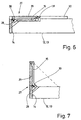
- eine perspektivische Darstellung eines Endes der Vorrichtung bei vollständig geöffneter Klappe,
- Fig. 6
- das Ende der Vorrichtung der Fig. 5 mit eingeklappter Klappe bei zusammengeklappter, leerer Vorrichtung,
- Fig. 7
- ein Ende der Vorrichtung in einer Darstellung gemäß der Fig. 6 bei in Transportposition hochgeklappter Rampe,
- Fig. 8
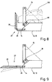
- ein Ende einer teilweise verlängerten Vorrichtung in einer Darstellung analog zu den Fig. 6 und 7 mit teilweise hochgeschwenkter Klappe, und
- Fig. 9
- ein Ende der Vorrichtung analog zu den Fig. 6 bis 8 mit vollständig geöffneter Klappe.
- Fig. 1
- Devices loaded with passenger cars (shown without side walls) on board a barge,
- Fig. 2
- an unloaded device in perspective with the walls partially folded up,
- Fig. 3
- 3 shows a cross section through a device currently loaded with a motor vehicle,
- Fig. 4
- an end portion of the empty and collapsed device,
- Fig. 5
- 2 shows a perspective view of one end of the device when the flap is fully open,
- Fig. 6
- 5 with the flap folded in when the empty device is folded,
- Fig. 7
- 6 one end of the device in a representation according to FIG. 6 with the ramp folded up in the transport position,
- Fig. 8
- one end of a partially elongated device in a representation analogous to FIGS. 6 and 7 with the flap partially pivoted up, and
- Fig. 9
- one end of the device analogous to FIGS. 6 to 8 with the flap fully open.
Die hier gezeigte Vorrichtung dient zum Transport von in den
Fig. 1, 3 und 8 gezeigten Kraftfahrzeugen auf insbesondere
Lkw's, Eisenbahnwaggons, Binnen- oder Seeschiffen. Die Fig. 2
zeigt mit Kraftfahrzeugen 10 beladene Vorrichtungen an Bord
eines Binnenschiffs 11.The device shown here is used to transport from the
1, 3 and 8 motor vehicles shown in particular
Trucks, railway wagons, inland or sea ships. 2
shows 10 loaded devices on board with motor vehicles
of an
Die hier gezeigten Vorrichtungen sind als Transportkäfige zur
Aufnahme von jeweils zwei Kraftfahrzeugen 10 ausgebildet. In
der Fig. 1 gezeigten unverlängerten Version entsprechen die Außenabmessungen
jeder Vorrichtung etwa der Außenabmessung eines
40' Containers. Die transportkäfigartigen Vorrichtungen sind
zusammen mit den darauf befindlichen Kraftfahrzeugen 10 wie
Container handhabbar. Die beladenen Vorrichtungen können zusammen
mit den darauf befindlichen Kraftfahrzeugen 10 wie Container
übereinander und nebeneinander an Bord des Binnenschiffs 11
gestaut werden. Auf Lkw oder Eisenbahnwaggons werden vorzugsweise
zwei Transportkäfige mit darauf befindlichen Kraftfahrzeugen
10 übereinander gestapelt transportiert. The devices shown here are used as transport cages
Recording of two
Im unbeladenen Zustand sind die Vorrichtungen zusammenklappbar, so daß eine größere Anzahl übereinander gestapelter transportkäfigartiger Vorrichtungen raumsparend transportiert werden kann.The devices are collapsible when unloaded, so that a larger number of stacked transport cage-like Devices can be transported to save space can.
Jede transportkäfigartige Vorrichtung verfügt Ober einen rechteckigen
Boden 12 mit zwei parallelen Längsseitenkanten 13 und
zwei parallelen (kürzeren) Querkanten 14 sowie verschenkbare
Stapelsäulen 15. Der Boden 12 ist rahmenartig aufgebaut, verfügt
nämlich über längs der Längsseitenkanten 13 verlaufende
Längsträger 18 und längs der Querkanten 14 verlaufende Querträger
19. Die von den Längsträgern 18 und den Querträgern 19
eingeschlossene Fläche kann mit weiteren, nicht gezeigten Versteifungsträgern
versehen sein. Auf dem von den Trägern gebildeten
Rahmen befinden sich zwei in Längsrichtung des Bodens 12
verlaufende, parallele Fahrbahnen 16 und 17 für die auf den
Vorrichtungen unterzubringenden Kraftfahrzeuge 10. Jedem der
vier Eckpunkte des rechteckförmigen Bodens 12 ist eine Stapelsäule
15 zugeordnet. In Transportstellung sind die Stapelsäulen
15 hochgeklappt, verlaufen also senkrecht zum etwa horizontalen
Boden 12. Um eine parallel zur Querkante 14 verlaufende
Schwenkachse 20 ist jede Stapelsäule 15 gegen die entsprechende
Längsseitenkante 13 verschwenkbar.Each transport cage-like device has a rectangular
Aus der Fig. 2 geht hervor, daß jeder Längsseitenkante 13 des
Bodens 12 eine Seitenwand 21 zugeordnet ist. Jede der gleich
ausgebildeten über die gesamte Länge der Vorrichtung zwischen
zwei auf der gleichen Seite angeordneten Stapelsäulen 15 verlaufende
Seitenwand 21 ist schwenkbar an der entsprechenden
Längsseitenkante 13 des Bodens 12 angelenkt. Zu diesem Zweck
dienen mehrere mit Abstand auf die Längsseitenkante 13 des Bodens
12 verteilt angeordnete Scharniere 22. In hochgeklapptem
Zustand (linke Darstellung der Fig. 2) sind senkrechte Stirnkanten
23 der entsprechenden Seitenwand 21 mit den ihnen zugeordneten
Stapelsäulen 15 verbindbar durch entsprechende Riegel.
Dadurch wird die jeweilige Seitenwand 21 in der hochgeklappten
Stellung arretiert und gleichzeitig eine stabile Verbindung der
jeweiligen Seitenwand 20 mit den gegenüberliegenden Stirnkanten
23 derselben zugeordneten Stapelsäulen 15 hergestellt. Somit
bildet jede Seitenwand 21 mit den beiden ihr zugeordneten
Stapelsäulen 15 und über die Scharniere 22 mit der entsprechenden
Längsseitenkante 13 des Bodens 12 eine Einheit.From Fig. 2 it can be seen that each
Infolge der erfindungsgemäß selbsttragenden bzw. lastaufnehmenden
Ausbildung der Seitenwände 21 tragen diese zur Stabilisierung
des Bodens 12 bei, und zwar insbesondere durch die die
Seitenwände 21 mit dem Boden 12 verbindenden Scharniere 22. Die
Seitenwände 21 bilden im hochgeklappten Zustand (linke Darstellung
der Fig. 2) einen seitlichen Schutz für die auf der tranportkäfigartigen
Vorrichtung untergebrachten Kraftfahrzeuge 10.
In heruntergeklapptem Zustand (rechte Darstellung der Fig. 2)
geben die Seitenwände 21 die Längsseiten der Vorrichtung frei,
wodurch die Kraftfahrzeuge 10 auf der Vorrichtung von der Seite
her zugänglich sind, insbesondere sich die Türen der
Kraftfahrzeuge 10 zum Ein- und Aussteigen von Fahrern nahezu
vollständig öffnen lassen.As a result of the self-supporting or load-bearing according to the invention
Formation of the
Ein nicht gezeigtes, alternatives Ausführungsbeispiel der Vorrichtung
verfügt über Seitenwände mit einem wie beim Ausführungsbeispiel
der Fig. 2 klappbar an den Längsseitenkanten 13
des Bodens 12 angelenkten Rahmen. Im Rahmen sind Seitenwandteil
bildende Schiebetüren angeordnet, die derart zueinander
verschoben werden können, daß bei beladener Vorrichtung die
rahmenartige Seitenwand vollständig geschlossen ist. Zum Beladen
der Vorrichtung können einzelne Seitenwandteile bildende
Schiebetüren verschoben werden, daß im entsprechenden Bereich
nur noch der Seitenwandrahmen übrig bleibt. Durch die geöffnete
Innenfläche desselben lassen sich dann geöffnete Türen des
Fahrzeugs hindurchschwenken, wodurch ein Fahrer leicht aus seinem
Fahrzeug aus- bzw. einsteigen kann.An alternative embodiment of the device, not shown
has side walls with one as in the embodiment
2 foldable on the longitudinal side edges 13
of the
Eine weitere, nicht gezeigte Alternative sieht vor, jede Seitenwand
aus tragfähigen bzw. lastaufnehmenden Seitenwandteilen
zu bilden, die verschiebbar an den Längsseitenkanten 13 des Bodens
12 angeordnet sind. Diese Verschiebbarkeit der Seitenwandteile
erfolgt derart, wie es bei zum Beispiel bei Schiebetürschränken
bekannt ist. In besonderer Weise ist die Führung der
verschiebbaren und belastbaren bzw. lastaufnehmenden Seitenwandteile
an der jeweiligen Längsseitenkante 13 des Bodens 12
gelagert. Hierbei handelt es sich um eine form- und kraftschlüssige
Lagerung, die es ermöglicht, auf den Boden 12 ausgeübte
Lasten auf die verschiebbaren Seitenwandteile zu übertragen,
wodurch diese eventuelle Durchbiegungen des Bodens 12 abfangen
bzw. reduzieren.Another alternative, not shown, provides for each side wall
from load-bearing or load-bearing side wall parts
to form the slidably on the longitudinal side edges 13 of the bottom
12 are arranged. This displaceability of the side wall parts
takes place in the same way as for example in sliding door wardrobes
is known. The leadership of the
sliding and resilient or load-bearing side wall parts
on the respective
Die Vorrichtung nach der Fig. 2 verfügt weiterhin an ihren
Querkanten 14 über Hände, nämlich Querwände, die als Klappen 24
ausgebildet sind. Die Klappen 24 sind vorzugsweise von den
Kraftfahrzeugen 10 befahrbar.The device according to FIG. 2 also has its
Cross edges 14 over hands, namely transverse walls, which act as
Jede Klappe 24 ist über ein Scharnier 25 oder gegebenenfalls
auch mehrere Scharniere um eine horizontale Schwenkachse klappbar
mit der jeweiligen Querkante des Bodens 12 verbunden. In
der aufgeklappten Stellung (linke Darstellung der Fig. 2) bildet
die jeweilige Klappe 24 eine horizontale Verlängerung des
Bodens 12 der Vorrichtung über die Querkante 14 hinaus. Die
Klappe 24 bildet so eine Rampe zum Überfahren von hintereinander
angeordneten Vorrichtungen. Darüber hinaus bildet die jeweilige
Klappe 24 aber auch eine Verlängerung des Bodens 12 der
Vorrichtung, wodurch die Vorrichtung mit längeren Kraftfahrzeugen
10 beladen werden kann, die gegebenenfalls während des
Transports mit Hinter- oder Vorderrädern auf der Klappe 24 stehenbleiben
können. Die dazu notwendige Stabilität der Klappe 24
in der ausgeklappten, horizontalen Stellung wird erreicht durch
einklappbare Streben 26 aus zwei gelenkig miteinander verbundenen
Hebel armen. Bei in die horizontale Lage geschwenkter Klappe
24 (linke Darstellung der Fig. 2) gelangen die Hebel arme der
Strebe 26 in eine gestreckte Stellung, wodurch eine zuverlässige
Lagesicherung der jeweiligen Klappe 24 in der den Boden 12
verlängernden horizontalen Lage gewährleistet ist.Each
Wird die Vorrichtung mit Fahrzeugen beladen, die nur den Bereich
des Bodens 12 in Anspruch nehmen, können nach dem Beladen
die Klappen 24 hochgeschwenkt werden in eine Transportstellung
(rechte Darstellung der Fig. 2). In diesem Falle werden die Hebelarme
der Streben 26 zusammengeklappt. Die hochgestellten
Klappen 24 bilden in der Transportposition Stirnwände der Vorrichtung,
die zum einen dazu dienen, die Fahrzeuge an der Vorder- oder Rückseite von außen zu schützen und zum anderen die
Vorrichtung stabilisieren. Zu diesem Zweck sind die hochgeschwenkten
Klappen 24 durch formschlüssige Verriegelungselemente
mit den gegenüberliegenden Seiten der Klappen 24 zugeordneten
Stapelsäulen 15 formschlüssig (aber lösbar) verbindbar.
Dadurch kommt eine stabilisierende Verbindung zwischen den
Klappen 24, dem Boden 12 und den den Klappen 24 zugeordneten
Stapelsäulen 15 zustande. Vor allem in Verbindung mit den Seitenwänden
21 (Fig. 2), aber auch den vorstehend beschriebenen
alternativen Ausführungsformen der Seitenwände, erhält die Vorrichtung
eine relativ hohe Verwindungssteifigkeit, bildet nämlich
eine oben offene kastenförmige Aufnahme für die Kraftfahrzeuge
10.The device is loaded with vehicles that only cover the area
of the
Bei einem anderen Ausführungsbeispiel der Vorrichtung (Fig. 5
bis 9) ist jedem Ende des Bodens 12 eine zweiteilige Klappe 27
zugeordnet. Auch diese Klappe 27 hat mehrere Funktionen, dient
nämlich sowohl als Auffahrrampe, als Verlängerung des Bodens 12
und/oder als Schutz der Kraftfahrzeuge 10. Jede zweiteilige
Klappe 27 ist mit nicht dargestellten Scharnieren an einer entsprechenden
Querkante 14 des Bodens 12 mit einem Innenteil 28
schwenkbar angelegt. Mit dem Innenteil 28 ist wiederum durch
nicht gezeigte Scharniere schwenkbar ein Außenteil 29 der
Klappe 27 angelenkt. Innenteil 28 und Außenteil 29 bilden somit
die beiden Teile jeder Klappe 27. In ausgeklappter Position der
Klappe 27 befinden sich sowohl das Innenteil 28 als auch das
Außenteil 29 etwa in der Ebene des Bodens 12 (Fig. 5 und 9).
Die jeweilige Klappe 27 dient dabei als Auf- und Abfahrrampe
für die Kraftfahrzeuge 10. Gleichzeitig bilden sowohl die Innenteile
28 als auch die Außenteile 29 horizontale Verlängerungen
gegenüberliegender Seiten des Bodens 12. Bei heruntergeschwenkten
Klappen 24 weist der dadurch beidseitig verlängerte
Boden 12 Abmessungen auf, die etwa einem 45' Container entsprechen.
Die Stapelsäulen 15 befinden sich dabei auf Rasterpunkten,
die denen eines 40' Containers entsprechen. In another embodiment of the device (FIG. 5
to 9) is a two-
Ist nur eine teilweise Verlängerung des Bodens 12 erforderlich,
kann in der Transportstellung der Vorrichtung nur das Innenteil
28 einer oder beider Klappen 24 heruntergeklappt sein in die
Ebene des Bodens 12, während das Außenteil 29 einer oder beider
Klappen 24 hochgeschwenkt, also angewinkelt ist (Fig. 8). Auf
diese Weise ist die Gesamtlänge der Vorrichtung dem Bedürfnis
entsprechend variierbar. Darüber hinaus bilden die hochgeschwenkten
Außenteile 29 einen vorderseitigen bzw. rückseitigen
Schutz der sich auf der Vorrichtung befindlichen Kraftfahrzeuge
10 (Fig. 8).If only a partial extension of the
Ist die Vorrichtung nur mit relativ kurzen Kraftfahrzeugen 10
beladen, die nicht über die Fläche des Bodens 12 hinausragen,
wird die oder jede Klappe 27 vollständig hochgeschwenkt, so daß
Innenteil 28 und Außenteil 29 in einer gemeinsamen, vertikalen
Ebene sich befinden (Fig. 7). Dann ist die gesamte Rückseite
und gegebenenfalls auch Vorderseite der Vorrichtung durch die
entsprechende Klappe 27 verschlossen, wodurch das vordere und
das hintere Kraftfahrzeug 10 vollständig geschützt sind.Is the device only with relatively
Bei leerer Vorrichtung mit eingeklappten Stapelsäulen 15 ist
das Innenteil 28 jeder Klappe 27 vollständig hochgeschwenkt, so
daß die Innenteile 28 eine senkrechte Position zum Boden 12
einnehmen (Fig. 6). Dem gegenüber sind die Außenteile 29 nach
innen in eine horizontale Position geschwenkt, befinden sich
dadurch zwischen den eingeklappten Stapelsäulen 15. Die leeren
Vorrichtungen mit eingeklappten Stapelsäulen 15 lassen sich somit
trotz der relativ langen, zweiteiligen Klappen 27 auf die
Grundfläche eines 40' Containers bringen, wobei die Höhe durch
die Oberseiten der eingeklappten Stapelsäulen 15 der Vorrichtung
bestimmt wird (Fig. 6).When the device is empty with the stacked
Die Stapelsäulen 15 sind gleich ausgebildet und verfügen jeweils
über eine längliche, kastenförmige Gestalt. Ein unteres
Ende jeder Stapelsäule 15 ist schwenkbar mit der jeweiligen
Ecke des Bodens 12 verbunden durch eine horizontale und parallel
zur Querkante 14 verlaufende Schwenkachse 30. Dadurch sind
die Stapelsäulen 15 in einer senkrecht zur jeweiligen Längsseitenkante
13 des Bodens 12 verlaufenden Ebene verschwenkbar
(Fig. 4). Ausgehend von jeder Ecke des Bodens 12 ist eine entlang
eines Teils der entsprechenden Längsseitenkante 13 verlaufende
Ausnehmung 31 vorgesehen, die korrespondierend zu den
Abmessungen jeweils einer Stapelsäule 15 ausgebildet sind. Die
Ausnehmungen 31 dienen so dazu, die in eine horizontale
Position heruntergeklappten Stapelsäulen 15 größtenteils aufzunehmen.
Auf diese Weise ragen die Oberseiten der hochgeklappten
Stapelsäulen 15 nicht nennenswert über die Oberseite des
Bodens 12 heraus (Fig. 4).The stacking
Im hochgeklappten Zustand ist jede Stapelsäule 15 mit einer
Strebe 32 gegenüber dem Boden 12 arretierbar. Jede einer
Stapelsäule 15 zugeordnete Strebe 32 ist mit einer senkrecht
zur jeweiligen Längsseitenkante des Bodens 12 verlaufenden
Ebene angeordnet. Ein Ende jeder Strebe 32 ist schwenkbar an
der jeweiligen Längsseitenkante 13 des Bodens 12 angelenkt. Das
gegenüberliegende Ende jeder Strebe 32 ist mit der entsprechenden
hochgeklappten Stapelsäule 15 verbindbar (Fig. 4). Bei heruntergeklappten
Stapelsäulen 15 sind die Streben 32 um den gelenkigen
Anlenkpunkt am Boden 12 gegen den Boden 12 verschwenkbar
(Fig. 4).In the folded-up state, each stacking
Sowohl das obere Ende als auch das untere Ende jeder Stapelsäule
15 ist mit einer bei hochgeklappter Stapelsäule 15 in
parallel zum Boden 12 horizontal verlaufenden Ebenen angeordneten
Platten versehen, in denen jeweils eine Verankerungsöffnung
33 und 34 angeordnet ist. Den Eckpunkten des Bodens 12
sind ebenfalls zwei parallele, horizontale Platten zugeordnet,
in denen jeweils eine Verankerungsöffnung 35, 36 sich befindet.
Die Platten mit den Verankerungsöffnungen 35, 36 können durch
handelsübliche Containereckbeschläge gebildet sein. Dann
befinden sich auch in aufrechten Stirn- und Seitenkanten des
Bodens 12 Verankerungsöffnungen.Both the top and bottom of each stacking
Die an der Unterseite jeder Stapelsäule 15 angeordnete Verankerungsöffnung
34 korrespondiert mit der an der Oberseite des Bodens
12 angeordneten Verankerungsöffnung 35 derart, daß beide
Verankerungsöffnungen 34 und 35 durch ein handelsübliches Kuppelstück,
beispielsweise ein Twistlock 37, miteinander formschlüssig
verbunden werden können. Dadurch werden die Stapelsäulen
15 zusätzlich in der hochgeklappten Transportstellung
der Vorrichtung arretiert. Die Schwenkachse 30 zur Verbindung
jeder Stapelsäule 15 mit dem Boden 12 ist so plaziert, daß bei
heruntergeklappten Stapelsäulen 15 die obere Verankerungsöffnung
35 am Boden 12 freiliegt. Diese Verankerungsöffnung 35
ist dadurch frei zugänglich zum Verbinden mehrerer übereinander
gestapelter leerer Vorrichtung mit eingeklappten Stapelsäulen
15 oder auch zum Ankuppeln von Hebezeugen.The anchoring opening arranged on the underside of each stacking
Die Verankerungsöffnung 33 am obere Ende jeder Stapelsäule 15
dient vorzugsweise auch zur Aufnahme eines Kuppelstücks, beispielsweise
eines Twistlocks 38 (Fig. 4). Die Twistlocks 38
dienen dann zur Verbindung zweier übereinander gestapelter Vorrichtungen,
indem der obere Teil des in die Verankerungsöffnung
33 am oberen Ende jeder Stapelsäule 15 eingesetzten Twistlocks
38 in die Verankerungsöffnung 36 an der Unterseite des Bodens
12 einer auf die untere Vorrichtung aufgesetzten Vorrichtung
eingreift.The anchoring
Alternativ ist es auch möglich, die Oberseite und/oder die Unterseite
jeder Stapelsäule 15 unmittelbar mit einem Kuppelstück
zu verbinden, und zwar vorzugsweise dauerhaft. Es können dann
die Verankerungsöffnungen 33 und 34 an der Oberseite und Unterseite
der Stapelsäulen 15 entfallen. Die dauerhaft an Ober- und
Unterseite jeder Stapelsäule 15 angebrachten Kuppelstücke können
bei Bedarf eingesetzt werden, um übereinander gestapelte
Vorrichtungen mit aufrechten, ausgeklappten Stapelsäulen 15
miteinander zu verbinden und um die in Transportstellung hochgeklappten
Stapelsäulen 15 in dieser Stellung zu arretieren`
indem der je an den Unterseiten der Stapelsäulen 15 dauerhaft
befestigten Kuppelstücke mit den Verankerungsöffnungen 35 an
der Oberseite des Bodens 12 verbunden werden.Alternatively, it is also possible for the top and / or the bottom
each stacking
Gemäß einer weiteren Ausgestaltung der Vorrichtung sind die
Fahrbahnen 16 und 17 mit unterschiedlichen Abständen zur Längsmittelachse
39 der Vorrichtung bzw. des Bodens 12 versehen. Im
gezeigten Ausführungsbeispiel (Fig. 3) weist die rechte Fahrbahn
17 einen größeren Abstand zur Längsmittelachse 39 auf als
die linke Fahrbahn 16. Auf diese Weise lassen sich die Kraftfahrzeuge
10 außermittig auf den Boden 12 der Vorrichtung fahren.
Dadurch entstehen unterschiedliche Abstände der gegenüberliegenden
Seiten der Kraftfahrzeuge 10 zu den Längsseitenkanten
13, weil die Mitten 40 der Kraftfahrzeuge 10 zur Längsmittelachse
39 des Bodens 12 der Vorrichtung versetzt sind. Im gezeigten
Ausführungsbeispiel befindet sich die Beifahrerseite
dicht an der Längsseitenkante 13, während die Fahrerseite einen
deutlichen Abstand zur gegenüberliegenden Längsseitenkante 13
aufweist. Dieser Abstand ist vor allem dann wichtig, wenn die
Vorrichtung mit den in Fig. 3 nicht gezeigten Seitenwänden 21
versehen ist. Dann kann nämlich auch noch bei geschlossenen
Seitenwänden 21 die Fahrertür soweit geöffnet werden, daß die
Fahrer der Kraftfahrzeuge 19 verhältnismäßig einfach ein- und
aussteigen können.According to a further embodiment of the
Im Ausführungsbeispiel der Fig. 3 sind Innenseiten von Trägern
zur Stabilisierung des Bodens 12 mit einem Schutzbelag 41 aus
zum Beispiel Gummi versehen. Dieser kann gegebenenfalls auch an
den Innenseiten bzw. Teilen der Seitenwände 21 angeordnet sein.In the exemplary embodiment in FIG. 3, inner sides of carriers
to stabilize the
Zur außermittigen Führung der Kraftfahrzeuge 10 auf dem Boden
12 ist eine längliche Führung 42 vorgesehen. Diese Führung 42
ist im gezeigten Ausführungsbeispiel an der Außenseite einer
Fahrbahn (in der Fig. 2 der linken Fahrbahn 16) angeordnet. Die
Führung 42 ist hier fest mit dem Boden 12 verbunden. Eine senkrechte
Handung 43 der Führung 42 befindet sich neben der entsprechenden
Fahrbahn 16 und sorgt hier für eine Führung der
linken Reifen 44 des jeweiligen Kraftfahrzeugs 10. Die Führung
42 bzw. die Wandung 43 haben so praktisch die Wirkung von Bordsteinen.For off-center guidance of
Alternativ ist es denkbar, die Führung 42 in insbesondere horizontaler
Richtung verstellbar auszubilden, derart, daß der Abstand
der aufrechten Wandung 43 der Führung 42 von der entsprechenden
Längsseitenkante 13 des Bodens 12 verändert werden
kann. Auf diese Weise ist eine Anpassung an unterschiedlich
breite Kraftfahrzeuge möglich, derart, daß diese mit der Beifahrerseite
sich so dicht wie möglich an der entsprechenden
Längsseitenkante 13 des Bodens befinden. Es ändern sich dazu
die Abstände der Fahrbahnen 16 und 17 zur Längsmittelachse 39
der Vorrichtung. Alternatively, it is conceivable to guide 42 in a more horizontal manner
To make the direction adjustable, such that the distance
the
- 1010th
- KraftfahrzeugMotor vehicle
- 1111
- BinnenschiffBarge
- 1212th
- Bodenground
- 1313
- LängsseitenkanteLong edge
- 1414
- QuerkanteTransverse edge
- 1515
- StapelsäuleStacking column
- 1616
- Fahrbahnroadway
- 1717th
- Fahrbahnroadway
- 1818th
- LängsträgerSide member
- 1919th
- QuerträgerCross member
- 2020th
- SchwenkachseSwivel axis
- 2121
- SeitenwandSide wall
- 2222
- Scharnierhinge
- 2323
- StirnkanteFront edge
- 2424th
- Klappeflap
- 2525th
- Scharnierhinge
- 2626
- Strebestrut
- 2727
- Klappeflap
- 2828
- Innenteilinner part
- 2929
- AußenteilOuter part
- 3030th
- SchwenkachseSwivel axis
- 3131
- AusnehmungRecess
- 3232
- Strebestrut
- 3333
- Verankerungsöffnung Anchoring opening
- 3434
- VerankerungsöffnungAnchoring opening
- 3535
- VerankerungsöffnungAnchoring opening
- 3636
- VerankerungsöffnungAnchoring opening
- 3737
- TwistlockTwistlock
- 3838
- TwistlockTwistlock
- 3939
- LängsmittelachseLongitudinal central axis
- 4040
- MittenIn the middle
- 4141
- SchutzbelagProtective covering
- 4242
- Führungguide
- 4343
- WandungWall
- 4444
- Reifentires
Claims (21)
Applications Claiming Priority (2)
| Application Number | Priority Date | Filing Date | Title |
|---|---|---|---|
| DE19730165 | 1997-07-14 | ||
| DE19730165A DE19730165A1 (en) | 1997-07-14 | 1997-07-14 | Device for transporting vehicles, in particular passenger cars, vans or the like |
Publications (3)
| Publication Number | Publication Date |
|---|---|
| EP0893366A2 true EP0893366A2 (en) | 1999-01-27 |
| EP0893366A3 EP0893366A3 (en) | 2000-01-05 |
| EP0893366B1 EP0893366B1 (en) | 2004-05-12 |
Family
ID=7835681
Family Applications (1)
| Application Number | Title | Priority Date | Filing Date |
|---|---|---|---|
| EP98113029A Expired - Lifetime EP0893366B1 (en) | 1997-07-14 | 1998-07-14 | Device for transporting vehicles, especially for estate cars, small vehicles or similar |
Country Status (4)
| Country | Link |
|---|---|
| EP (1) | EP0893366B1 (en) |
| DE (2) | DE19730165A1 (en) |
| DK (1) | DK0893366T3 (en) |
| ES (1) | ES2221695T3 (en) |
Cited By (8)
| Publication number | Priority date | Publication date | Assignee | Title |
|---|---|---|---|---|
| GB2376014A (en) * | 2001-04-10 | 2002-12-04 | Martin Clive-Smith | Folding flatrack with outward bracing |
| WO2004041679A1 (en) * | 2002-11-07 | 2004-05-21 | Martin Clive-Smith | Collapsible flat rack |
| CN103144644A (en) * | 2012-11-26 | 2013-06-12 | 南车长江车辆有限公司 | Railway side dump car |
| US8608415B2 (en) | 2010-09-29 | 2013-12-17 | Raildecks (2009), Inc. | Intermodal transport platform |
| US8714895B2 (en) | 2010-09-29 | 2014-05-06 | Raildecks (2009), Inc. | Collapsible intermodal transport platform |
| US9004832B1 (en) | 2012-05-14 | 2015-04-14 | Raildecks (2009), Inc. | Intermodal container |
| CN105416882A (en) * | 2015-12-29 | 2016-03-23 | 龙口丛林中德车体系统工程有限公司 | Integrated transport tool for vehicle body large components of rail transit vehicle |
| DE102016005417A1 (en) * | 2016-05-02 | 2017-11-02 | René Schaedler | load floor |
Families Citing this family (3)
| Publication number | Priority date | Publication date | Assignee | Title |
|---|---|---|---|---|
| KR100744815B1 (en) * | 2005-12-19 | 2007-08-01 | 김점규 | Vehicle loading containers |
| EP2027007A4 (en) * | 2006-06-14 | 2009-08-05 | Ben Alder Pty Ltd | A mobile storage system and method of managing the use of same |
| US11485573B1 (en) * | 2021-09-20 | 2022-11-01 | Ramp Container LLC | Container with at least one ramp wall |
Family Cites Families (28)
| Publication number | Priority date | Publication date | Assignee | Title |
|---|---|---|---|---|
| DE8216085U1 (en) * | 1982-11-25 | Eloxal Becker & Oswald GmbH & Co KG, 6544 Kirchberg | Collapsible long goods container | |
| DE8007586U1 (en) * | 1980-07-03 | Kaufmann & Lindgens Gmbh & Co Kg, 5144 Wegberg | Collapsible long goods cassette | |
| FR1212465A (en) * | 1959-06-08 | 1960-03-24 | Botrans | Device for securing vehicles on wagons |
| FR1254559A (en) * | 1960-01-15 | 1961-02-24 | Venissieux Atel | Flat wagon for transporting motor vehicles |
| DE1284610C2 (en) * | 1966-11-04 | 1973-01-25 | Karl Haegele Dipl Ing | Platform for parking one vehicle on top of another |
| GB1258284A (en) * | 1968-10-02 | 1971-12-30 | ||
| US3801177A (en) * | 1971-06-04 | 1974-04-02 | Fmc Corp | Frameless shipping container |
| DE7713630U1 (en) * | 1977-04-29 | 1977-09-29 | Plan Transport Equipment Ltd | Device for locking the corner pillars of a transport device (Klappflat) or for locking the transport device with a similar device |
| FR2419191A1 (en) * | 1978-03-07 | 1979-10-05 | Jige Remorques Indles | Lorry with rigidly mounted load bed - has hinged legs near front to incline bed for loading and unloading |
| GB8328068D0 (en) * | 1983-10-20 | 1983-11-23 | Lawrence David Ltd | Container with slidable doors |
| US5265748A (en) * | 1987-12-10 | 1993-11-30 | Shigenobu Furukawa | Multi-purpose container |
| JPH02139381A (en) * | 1988-07-20 | 1990-05-29 | Shigenobu Furukawa | Passenger car transport container |
| US4966510A (en) * | 1989-06-06 | 1990-10-30 | Johnson Jr James N | Trailer for transporting golf carts and the like |
| DE9010938U1 (en) * | 1990-07-24 | 1990-10-18 | Kimm, Bruno, 3500 Kassel | Device for the storage and transport of motor vehicles, in particular cars |
| DE9103785U1 (en) * | 1991-03-14 | 1991-06-20 | Lokomotivbau-Elektrotechnische Werke Hennigsdorf GmbH, O-1422 Hennigsdorf | Emergency exit door for rail vehicles |
| FR2677622B1 (en) * | 1991-06-11 | 1995-01-06 | Lohr Ind | MULTIPURPOSE UNIVERSAL CONTAINER WITH MAXIMUM CAPACITY. |
| US5344203A (en) * | 1992-03-09 | 1994-09-06 | Tollenaere Donald J | Aerodynamically-stabilized collapsible personnel and cargo basket for helicopters |
| FR2695087B1 (en) * | 1992-09-03 | 1994-09-30 | Lohr Ind | Mixed double floor convertible into a vehicle structure for transport unit. |
| DE9214306U1 (en) * | 1992-10-23 | 1993-06-17 | BWR Werkstoff-Systeme und Fahrzeugbau GmbH, 7550 Rastatt | Loading platform |
| DE9307281U1 (en) * | 1993-02-22 | 1993-07-15 | Hagemann & Partner Gesellschaft für Umwelttechnik mbH, 1000 Berlin | Collection container |
| US5690453A (en) * | 1994-04-15 | 1997-11-25 | Global Transport Systems, Inc. | Method and apparatus for transporting cars |
| DE29516152U1 (en) * | 1994-10-11 | 1995-11-30 | Bodack, Karl-Dieter, 82194 Gröbenzell | Car transport car |
| GB9421349D0 (en) * | 1994-10-24 | 1994-12-07 | Clive Smith Martin | Collapsible flatrack with removable walls |
| US5730578A (en) * | 1995-02-15 | 1998-03-24 | Wabash National Corporation | Lifting mechanism for a deck system |
| GB2298842A (en) * | 1995-02-28 | 1996-09-18 | Treton Developments Inc | Motor vehicle transportation |
| GB2303360B (en) * | 1995-07-19 | 1999-12-08 | Clive Smith Martin | Collapsible Shipping Container |
| DE19620909A1 (en) * | 1995-10-24 | 1997-04-30 | Clive Smith Martin | Collapsible platform based cargo carrier |
| ES2130032B1 (en) * | 1995-11-29 | 2000-01-16 | Fine Products S A | IMPROVEMENTS IN THE PURPOSE OF PATENT 9600259 RELATING TO A SET OF DOOR AND EVACUATION RAMP FOR TRAVELERS 'MEANS OF TRANSPORTATION. |
-
1997
- 1997-07-14 DE DE19730165A patent/DE19730165A1/en not_active Withdrawn
-
1998
- 1998-07-14 DK DK98113029T patent/DK0893366T3/en active
- 1998-07-14 EP EP98113029A patent/EP0893366B1/en not_active Expired - Lifetime
- 1998-07-14 DE DE59811360T patent/DE59811360D1/en not_active Expired - Lifetime
- 1998-07-14 ES ES98113029T patent/ES2221695T3/en not_active Expired - Lifetime
Cited By (14)
| Publication number | Priority date | Publication date | Assignee | Title |
|---|---|---|---|---|
| GB2376014A (en) * | 2001-04-10 | 2002-12-04 | Martin Clive-Smith | Folding flatrack with outward bracing |
| WO2004041679A1 (en) * | 2002-11-07 | 2004-05-21 | Martin Clive-Smith | Collapsible flat rack |
| CN100463817C (en) * | 2002-11-07 | 2009-02-25 | 马丁·克莱夫-史密斯 | foldable platform deck |
| US9227756B2 (en) | 2010-09-29 | 2016-01-05 | Raildecks (2009), Inc. | Intermodal transport platform |
| US8608415B2 (en) | 2010-09-29 | 2013-12-17 | Raildecks (2009), Inc. | Intermodal transport platform |
| US8678727B2 (en) | 2010-09-29 | 2014-03-25 | Raildecks (2009), Inc. | Stacking system for intermodal platforms |
| US8714895B2 (en) | 2010-09-29 | 2014-05-06 | Raildecks (2009), Inc. | Collapsible intermodal transport platform |
| US8757943B2 (en) | 2010-09-29 | 2014-06-24 | Raildecks (2009), Inc. | Intermodal transport platform |
| US9004832B1 (en) | 2012-05-14 | 2015-04-14 | Raildecks (2009), Inc. | Intermodal container |
| CN103144644A (en) * | 2012-11-26 | 2013-06-12 | 南车长江车辆有限公司 | Railway side dump car |
| CN103144644B (en) * | 2012-11-26 | 2015-12-23 | 南车长江车辆有限公司 | A kind of railway automatic dumping car |
| CN105416882A (en) * | 2015-12-29 | 2016-03-23 | 龙口丛林中德车体系统工程有限公司 | Integrated transport tool for vehicle body large components of rail transit vehicle |
| CN105416882B (en) * | 2015-12-29 | 2017-09-19 | 山东诺维科轻量化装备有限公司 | Rail traffic vehicles car body big parts integral type transport frock |
| DE102016005417A1 (en) * | 2016-05-02 | 2017-11-02 | René Schaedler | load floor |
Also Published As
| Publication number | Publication date |
|---|---|
| EP0893366A3 (en) | 2000-01-05 |
| DK0893366T3 (en) | 2004-09-06 |
| EP0893366B1 (en) | 2004-05-12 |
| DE19730165A1 (en) | 1999-01-21 |
| ES2221695T3 (en) | 2005-01-01 |
| DE59811360D1 (en) | 2004-06-17 |
Similar Documents
| Publication | Publication Date | Title |
|---|---|---|
| DE2731386C2 (en) | ||
| DE2401487A1 (en) | MATERIAL TRANSPORT CONTAINER | |
| DE202016008705U1 (en) | Liftable carrying device | |
| EP2684757B1 (en) | Freight cars | |
| EP0893366A2 (en) | Device for transporting vehicles, especially for estate cars, small vehicles or similar | |
| EP1884438A2 (en) | Wheeled container for piece goods | |
| CH617133A5 (en) | ||
| EP2589486B1 (en) | Storage and transport apparatus for receiving tire | |
| DE69308971T2 (en) | Convertible, double floor for motor vehicles in a transport unit | |
| EP0215227B1 (en) | Beverage-delivering vehicle | |
| DE60202890T2 (en) | Rail vehicle for alternate use for rail and road transport of road vehicles | |
| EP1690810B1 (en) | Collapsible container | |
| DE3805375C2 (en) | ||
| EP2955086B1 (en) | Commercial vehicle structure with pivoting side wall element | |
| EP0508404A1 (en) | Security device for a transport frame | |
| DE10051678C2 (en) | Equipment for transport containers, in particular lattice box transport pallets | |
| DE202008017410U1 (en) | Container | |
| CH621095A5 (en) | ||
| EP2388208A2 (en) | Transport container with top cover | |
| DE19529045B4 (en) | Swap body for transport vehicles | |
| DE29620358U1 (en) | Transport vehicle, in particular trucks or trailers, with a loading area and with at least one ramp | |
| DE10314378A1 (en) | Box-shaped closed superstructure for trucks and truck trailers comprises at least one side wall with slidable and foldable doors and slidable struts supporting a roof on a floor | |
| CH692947A5 (en) | Cargo container with platform has two longitudinal rails permitting it to be drawn over two first rollers onto transport vehicle of first type suitable for flat platforms | |
| WO2020240045A1 (en) | Multi-track vehicle for conveying loads | |
| DE4023437C2 (en) | Motor vehicle or motor vehicle trailer |
Legal Events
| Date | Code | Title | Description |
|---|---|---|---|
| PUAI | Public reference made under article 153(3) epc to a published international application that has entered the european phase |
Free format text: ORIGINAL CODE: 0009012 |
|
| AK | Designated contracting states |
Kind code of ref document: A2 Designated state(s): DE DK ES FR GB |
|
| AX | Request for extension of the european patent |
Free format text: AL;LT;LV;MK;RO;SI |
|
| PUAL | Search report despatched |
Free format text: ORIGINAL CODE: 0009013 |
|
| RTI1 | Title (correction) |
Free format text: DEVICE FOR TRANSPORTING VEHICLES, ESPECIALLY FOR ESTATE CARS, SMALL VEHICLES OR SIMILAR |
|
| AK | Designated contracting states |
Kind code of ref document: A3 Designated state(s): AT BE CH CY DE DK ES FI FR GB GR IE IT LI LU MC NL PT SE |
|
| AX | Request for extension of the european patent |
Free format text: AL;LT;LV;MK;RO;SI |
|
| 17P | Request for examination filed |
Effective date: 20000328 |
|
| AKX | Designation fees paid |
Free format text: DE DK ES FR GB |
|
| 17Q | First examination report despatched |
Effective date: 20011207 |
|
| GRAH | Despatch of communication of intention to grant a patent |
Free format text: ORIGINAL CODE: EPIDOS IGRA |
|
| GRAS | Grant fee paid |
Free format text: ORIGINAL CODE: EPIDOSNIGR3 |
|
| RAP1 | Party data changed (applicant data changed or rights of an application transferred) |
Owner name: MACGREGOR-CONVER GMBH |
|
| RIN1 | Information on inventor provided before grant (corrected) |
Inventor name: GLOYSTEIN, JUERGEN, DIPL.-ING. |
|
| GRAA | (expected) grant |
Free format text: ORIGINAL CODE: 0009210 |
|
| AK | Designated contracting states |
Kind code of ref document: B1 Designated state(s): DE DK ES FR GB |
|
| REG | Reference to a national code |
Ref country code: GB Ref legal event code: FG4D Free format text: NOT ENGLISH |
|
| REF | Corresponds to: |
Ref document number: 59811360 Country of ref document: DE Date of ref document: 20040617 Kind code of ref document: P |
|
| REG | Reference to a national code |
Ref country code: DK Ref legal event code: T3 |
|
| GBT | Gb: translation of ep patent filed (gb section 77(6)(a)/1977) |
Effective date: 20040818 |
|
| REG | Reference to a national code |
Ref country code: ES Ref legal event code: FG2A Ref document number: 2221695 Country of ref document: ES Kind code of ref document: T3 |
|
| ET | Fr: translation filed | ||
| PLBE | No opposition filed within time limit |
Free format text: ORIGINAL CODE: 0009261 |
|
| STAA | Information on the status of an ep patent application or granted ep patent |
Free format text: STATUS: NO OPPOSITION FILED WITHIN TIME LIMIT |
|
| 26N | No opposition filed |
Effective date: 20050215 |
|
| PGFP | Annual fee paid to national office [announced via postgrant information from national office to epo] |
Ref country code: ES Payment date: 20080821 Year of fee payment: 11 Ref country code: DK Payment date: 20080721 Year of fee payment: 11 |
|
| PGFP | Annual fee paid to national office [announced via postgrant information from national office to epo] |
Ref country code: FR Payment date: 20080718 Year of fee payment: 11 |
|
| PGFP | Annual fee paid to national office [announced via postgrant information from national office to epo] |
Ref country code: GB Payment date: 20080716 Year of fee payment: 11 |
|
| REG | Reference to a national code |
Ref country code: DK Ref legal event code: EBP |
|
| GBPC | Gb: european patent ceased through non-payment of renewal fee |
Effective date: 20090714 |
|
| REG | Reference to a national code |
Ref country code: FR Ref legal event code: ST Effective date: 20100331 |
|
| PG25 | Lapsed in a contracting state [announced via postgrant information from national office to epo] |
Ref country code: FR Free format text: LAPSE BECAUSE OF NON-PAYMENT OF DUE FEES Effective date: 20090731 |
|
| PG25 | Lapsed in a contracting state [announced via postgrant information from national office to epo] |
Ref country code: GB Free format text: LAPSE BECAUSE OF NON-PAYMENT OF DUE FEES Effective date: 20090714 |
|
| PG25 | Lapsed in a contracting state [announced via postgrant information from national office to epo] |
Ref country code: DK Free format text: LAPSE BECAUSE OF NON-PAYMENT OF DUE FEES Effective date: 20090731 |
|
| REG | Reference to a national code |
Ref country code: ES Ref legal event code: FD2A Effective date: 20090715 |
|
| PG25 | Lapsed in a contracting state [announced via postgrant information from national office to epo] |
Ref country code: ES Free format text: LAPSE BECAUSE OF NON-PAYMENT OF DUE FEES Effective date: 20090715 |
|
| PGFP | Annual fee paid to national office [announced via postgrant information from national office to epo] |
Ref country code: DE Payment date: 20100821 Year of fee payment: 13 |
|
| PG25 | Lapsed in a contracting state [announced via postgrant information from national office to epo] |
Ref country code: DE Free format text: LAPSE BECAUSE OF NON-PAYMENT OF DUE FEES Effective date: 20120201 |
|
| REG | Reference to a national code |
Ref country code: DE Ref legal event code: R119 Ref document number: 59811360 Country of ref document: DE Effective date: 20120201 |