EP0893375A1 - Abstreifpflug zum Reinigen von Förderbändern - Google Patents
Abstreifpflug zum Reinigen von Förderbändern Download PDFInfo
- Publication number
- EP0893375A1 EP0893375A1 EP98305361A EP98305361A EP0893375A1 EP 0893375 A1 EP0893375 A1 EP 0893375A1 EP 98305361 A EP98305361 A EP 98305361A EP 98305361 A EP98305361 A EP 98305361A EP 0893375 A1 EP0893375 A1 EP 0893375A1
- Authority
- EP
- European Patent Office
- Prior art keywords
- scraper
- plough
- plough scraper
- belt
- lever
- Prior art date
- Legal status (The legal status is an assumption and is not a legal conclusion. Google has not performed a legal analysis and makes no representation as to the accuracy of the status listed.)
- Granted
Links
Images

Classifications
-
- B—PERFORMING OPERATIONS; TRANSPORTING
- B65—CONVEYING; PACKING; STORING; HANDLING THIN OR FILAMENTARY MATERIAL
- B65G—TRANSPORT OR STORAGE DEVICES, e.g. CONVEYORS FOR LOADING OR TIPPING, SHOP CONVEYOR SYSTEMS OR PNEUMATIC TUBE CONVEYORS
- B65G45/00—Lubricating, cleaning, or clearing devices
- B65G45/10—Cleaning devices
- B65G45/12—Cleaning devices comprising scrapers
- B65G45/16—Cleaning devices comprising scrapers with scraper biasing means
Definitions
- This invention is concerned with a plough scraper.
- a plough scraper e.g. of a V or angle shape, is used to deflect material from an inner surface of a return strand of a conveyor belt.
- This type of scraper may be mounted on levers or chains to enable the height of the scraper to fluctuate as the belt flaps or otherwise moves in a vertical direction.
- Substantial flapping movement of a conveyor belt can for example take place when the belt is inclined.
- a simple yet rather crude approach to ensure that the scraper is kept in contact with the belt is simply to apply weights to the scraper to bias it into position with the belt surface which is to be scraped. This approach however can, under certain conditions, cause the scraper to dig into the belt, an event which can lead to considerable damage.
- the invention provides a mounting arrangement for a plough scraper for use with a conveyor belt which includes leading and trailing support members which are spaced from each other in the direction in which the conveyor belt extends, at least a first lever which is pivotally movable relatively to the trailing support member and which is pivotally attached to the plough scraper, means for biasing the first lever so that the plough scraper is urged towards the belt, and at least a second lever which is pivotally attached to the leading support member and to the plough scraper.
- the first lever may be engaged with the plough scraper at a central location of the scraper, transversely to the direction of belt movement, when viewed in plan.
- the first lever may for example be pivotally attached to the plough scraper at a first point which, viewed from the side, is on the leading side of the trailing support member e.g. between the trailing support member and the leading support member.
- any suitable biasing device may be used for urging the plough scraper towards the belt.
- a torsion member which is made from a rubber or other resilient material, a coil spring, or the like. It is preferred that the biasing member, over the range of pivotal movement of the first lever which is possible, exerts a substantially constant biasing force.
- Use may be made of two of the second levers which are connected to the plough scraper at spaced points, viewed in plan, transversely to the direction of belt movement.
- the second levers may be attached to the plough scraper at points which are on the trailing side of the leading support member i.e. between the leading and the trailing support members.
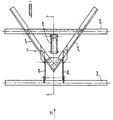
- FIG. 1 illustrates a plough scraper assembly according to the invention which includes a V-shaped plough scraper 10 which is substantially of conventional construction and a mounting arrangement 12 which supports the scraper above a surface 14 of a conveyor belt 16 which is moving in a direction 18 relatively to the assembly.
- the plough scraper 10 includes two scraping elements 20 and 22 which are arranged in a V configuration, as is shown in Figure 1.
- the mounting arrangement 12 includes a leading support member 24 and a trailing support member 26 which are positioned horizontally spaced from one another above the belt 16 and which extend transversely relatively to the direction 18.
- the members 24 and 26 are attached to existing conveyor support structure, not shown.
- the scraper 10 is attached to the trailing support member 26 by means of two articulated levers 28 and 30.
- a coil spring 32 acts between the levers 28 and 30 and biases the lever 30 downwardly so that the scraper 10 is urged towards the surface 14.
- the leading support member 24 has two transversely spaced levers 34 and 36 respectively which are pivotally attached to the support 24 for movement about an axis 38 and, at lower ends, to the scraper 10 for movement about an axis 40.
- the axis 40 is on the trailing side of the leading support member and is positioned between the support members 24 and 26.
- the lever 30 is attached to the plough scraper 10 at a pivot point 42 which is on the leading side of the trailing support member 26 and is positioned between the support members 24 and 26, when viewed from the side.
- the plough scraper is thus suspended from the support members 24 and 26 at three spaced pivot points.
- the levers 34 and 36 can move independently, to a limited extent, from each other and consequently the scraper 10 is able to tilt laterally relatively to the direction 18 and, viewed from the side, can vary its inclination relatively to the belt 16.
- the scraper can also move vertically up and down relatively to the belt.
- the biasing force which is exerted by the spring 32 is applied at an intermediate position to the plough scraper.
- the leading pointed end of the scraper on the other hand, subject to any restraining action exerted by the levers 34 and 36, is able to float. Due to gravity action and due to the biasing force of the spring 32 the scraper 10 is urged into scraping contact with the surface 14.
- the mounting arrangement which has been described has been found to be particularly effective in maintaining the scraper in contact with the surface 14 while simultaneously permitting the scraper to move as the belt 16 moves vertically up and down. Due to the fact that the axis 40 trails the axis 38 any tendency of the scraper to dig into the surface 14, as the belt 16 moves in a vertical direction, is reduced. On the other hand firm scraping engagement of the scraping elements 22 and 20 with the surface 14 is maintained by means of the spring 32.
- a biasing component which acts between the levers 28 and 30 which is able to exert a substantially constant biasing force over the required extent of movement of the lever 30 relatively to the lever 28.
- a multi turn coil spring 32 is particularly suitable for this purpose although other devices such as rubber or similar elastomeric torsion elements can be used in place of or in addition to the spring.
- Figure 2 illustrates the assembly with the belt 16 in an uppermost position and relatively close to the support members 24 and 26.
- Figure 3 on the other hand illustrates the belt 16 displaced from the support members.
- the mounting arrangement will take on an orientation similar to that shown in Figure 3 when the belt 16 moves downwardly relatively to the support members 24 and 26 or when the scraping elements 20 and 22 are substantially wom.
- a restraining device such as a chain or rod 46 is connected between the pivot points X and Y, shown in Figure 3. This device will stop the elements from descending further and the scraper will only move laterally, from time to time, due to its contact with the conveyor belt.
- the restraining device is preferably adjustable in length to permit the maximum spacing between the points X and Y to be set.
Landscapes
- Engineering & Computer Science (AREA)
- Mechanical Engineering (AREA)
- Structure Of Belt Conveyors (AREA)
- Belt Conveyors (AREA)
Applications Claiming Priority (2)
| Application Number | Priority Date | Filing Date | Title |
|---|---|---|---|
| ZA976408 | 1997-07-21 | ||
| ZA9706408 | 1997-07-21 |
Publications (2)
| Publication Number | Publication Date |
|---|---|
| EP0893375A1 true EP0893375A1 (de) | 1999-01-27 |
| EP0893375B1 EP0893375B1 (de) | 2001-10-17 |
Family
ID=25586485
Family Applications (1)
| Application Number | Title | Priority Date | Filing Date |
|---|---|---|---|
| EP98305361A Expired - Lifetime EP0893375B1 (de) | 1997-07-21 | 1998-07-06 | Abstreifpflug zum Reinigen von Förderbändern |
Country Status (5)
| Country | Link |
|---|---|
| US (1) | US5875881A (de) |
| EP (1) | EP0893375B1 (de) |
| AU (1) | AU741685B2 (de) |
| DE (1) | DE69802049T2 (de) |
| ES (1) | ES2162392T3 (de) |
Cited By (2)
| Publication number | Priority date | Publication date | Assignee | Title |
|---|---|---|---|---|
| DE19955421B4 (de) * | 1999-11-18 | 2004-07-15 | Haßelbeck, Jörg | Materialabstreifer für einen Fördergurt |
| CN103935750A (zh) * | 2014-04-14 | 2014-07-23 | 山东山矿机械有限公司 | 带式输送机的卸料系统 |
Families Citing this family (16)
| Publication number | Priority date | Publication date | Assignee | Title |
|---|---|---|---|---|
| AU738112B2 (en) * | 1997-07-25 | 2001-09-06 | Scorpio Conveyor Products (Proprietary) Limited | Conveyor scraper and mounting of scraper blade |
| US6860378B1 (en) | 2003-11-11 | 2005-03-01 | Thor Global Enterprises Ltd. | Belt scraper tensioning device |
| US20060182576A1 (en) * | 2005-01-31 | 2006-08-17 | Foster Raymond K | Clean out apparatus for reciprocating slat conveyor |
| US7584835B2 (en) * | 2005-03-11 | 2009-09-08 | Asgco Manufacturing, Inc. | Adjustable V-plow apparatus for deflecting material carried on a belt |
| US7383941B2 (en) * | 2005-08-18 | 2008-06-10 | Honda Motor Co., Ltd. | Bolt diversion system |
| DE102007042653A1 (de) * | 2007-09-10 | 2009-03-12 | HOSCH-FöRDERTECHNIK RECKLINGHAUSEN GMBH | Vorrichtung zum Abstreifen von Verunreinigungen eines Gurtbandes von Förderbandanlagen |
| US7882943B1 (en) | 2009-06-25 | 2011-02-08 | Schoonover Albert G | Plow for a conveyor belt |
| US8668077B2 (en) * | 2010-03-10 | 2014-03-11 | Tasman-Warajay Pty Ltd | Belt plough |
| CA2872767C (en) | 2012-05-08 | 2020-08-04 | Asgco Manufacturing, Inc. | Flip-able v-plow belt cleaner |
| US9253945B2 (en) | 2012-09-14 | 2016-02-09 | Cnh Industrial America Llc | Self-adjusting object deflector for an agricultural harvester feeder |
| US8662282B1 (en) * | 2012-11-07 | 2014-03-04 | Ford Motor Company | Pallet conveyor debris wiper |
| CN103625882B (zh) * | 2013-11-11 | 2016-06-29 | 中联重科股份有限公司 | 带式输送机的清扫器及物料输送设备 |
| JP6585147B2 (ja) | 2017-12-01 | 2019-10-02 | 浜松ホトニクス株式会社 | アクチュエータ装置 |
| US11394284B2 (en) * | 2017-12-01 | 2022-07-19 | Hamamatsu Photonics K.K. | Actuator device |
| CA3046751A1 (en) | 2019-06-17 | 2020-12-17 | Lyndon Graff | Belt conveyor capable of conveying oilseed products |
| US20210394395A1 (en) * | 2020-06-19 | 2021-12-23 | Nitrocrete Ip, Llc | Plow assembly for aggregate cooling in concrete manufacturing |
Citations (2)
| Publication number | Priority date | Publication date | Assignee | Title |
|---|---|---|---|---|
| US4944386A (en) * | 1990-01-08 | 1990-07-31 | Martin Engineering Company | Scraper for conveyor belts |
| DE4420511A1 (de) * | 1994-06-13 | 1995-12-14 | Kalenborn Gmbh Ind Tech | Rotationsabstreifer |
Family Cites Families (4)
| Publication number | Priority date | Publication date | Assignee | Title |
|---|---|---|---|---|
| US1933485A (en) * | 1932-12-27 | 1933-10-31 | Rund Ingvald | Cleaning apparatus for belt conveyers |
| US3865232A (en) * | 1973-09-11 | 1975-02-11 | Litton Systems Inc | Plow scraper for conveyor belts |
| NL8603104A (nl) * | 1986-12-05 | 1988-07-01 | Hcc Ede Bv | Transportband. |
| US5412461A (en) * | 1994-05-05 | 1995-05-02 | Xerox Corporation | Friction load insensitive mounting for blade |
-
1998
- 1998-07-06 DE DE69802049T patent/DE69802049T2/de not_active Expired - Fee Related
- 1998-07-06 ES ES98305361T patent/ES2162392T3/es not_active Expired - Lifetime
- 1998-07-06 US US09/110,140 patent/US5875881A/en not_active Expired - Fee Related
- 1998-07-06 AU AU74178/98A patent/AU741685B2/en not_active Ceased
- 1998-07-06 EP EP98305361A patent/EP0893375B1/de not_active Expired - Lifetime
Patent Citations (2)
| Publication number | Priority date | Publication date | Assignee | Title |
|---|---|---|---|---|
| US4944386A (en) * | 1990-01-08 | 1990-07-31 | Martin Engineering Company | Scraper for conveyor belts |
| DE4420511A1 (de) * | 1994-06-13 | 1995-12-14 | Kalenborn Gmbh Ind Tech | Rotationsabstreifer |
Cited By (3)
| Publication number | Priority date | Publication date | Assignee | Title |
|---|---|---|---|---|
| DE19955421B4 (de) * | 1999-11-18 | 2004-07-15 | Haßelbeck, Jörg | Materialabstreifer für einen Fördergurt |
| CN103935750A (zh) * | 2014-04-14 | 2014-07-23 | 山东山矿机械有限公司 | 带式输送机的卸料系统 |
| CN103935750B (zh) * | 2014-04-14 | 2016-04-27 | 山东山矿机械有限公司 | 带式输送机的卸料系统 |
Also Published As
| Publication number | Publication date |
|---|---|
| EP0893375B1 (de) | 2001-10-17 |
| US5875881A (en) | 1999-03-02 |
| AU741685B2 (en) | 2001-12-06 |
| ES2162392T3 (es) | 2001-12-16 |
| DE69802049D1 (de) | 2001-11-22 |
| AU7417898A (en) | 1999-01-28 |
| DE69802049T2 (de) | 2002-03-14 |
Similar Documents
| Publication | Publication Date | Title |
|---|---|---|
| US5875881A (en) | Plough scraper mounting arrangement | |
| US5082106A (en) | Stripping device for the return run of conveyor belts | |
| US5114000A (en) | Stripping device for cleaning conveyor belts | |
| US6125491A (en) | Counterbalance for mechanical dock leveler | |
| EP0634347A1 (de) | Kratzvorrichtung für Bandförderer | |
| EP0338118B1 (de) | Bandreiniger und dessen Kratzer | |
| AU2012202227B2 (en) | Belt cleaner | |
| US4036351A (en) | Conveyor belt cleaner | |
| US4678076A (en) | Transfer assembly of belt conveyor | |
| US4541523A (en) | Conveyor belt scraper | |
| GB2142899A (en) | Counterbalancing mechanism for the ramp of a dockboard | |
| US7017220B2 (en) | Spring counterbalance method and apparatus for variably biasing a dock leveler | |
| RU2543445C2 (ru) | Устройство соскабливания материала с нижней ветви ленточного конвейера | |
| US2990941A (en) | Load driving members of conveyors | |
| US4525888A (en) | Maintaining constant pick-up broom pattern | |
| US4501452A (en) | Bulldozer track support roller mounting | |
| US6575294B1 (en) | Conveyor belt skirt assembly | |
| US5051174A (en) | Bar screen rake apparatus | |
| US4352425A (en) | Belt cleaner | |
| GB2125357A (en) | Conveyor belt scraper mounting | |
| GB1581990A (en) | Suspension for vehicles | |
| US6193055B1 (en) | Conveyor belt support | |
| EP0447498A1 (de) | Selbstregelnde schiebeanlage eines schalters für das gewicht auf der fahrwerkanzeige | |
| US4848540A (en) | Skirt seal impact bracket | |
| US5095997A (en) | Floating track erasers |
Legal Events
| Date | Code | Title | Description |
|---|---|---|---|
| PUAI | Public reference made under article 153(3) epc to a published international application that has entered the european phase |
Free format text: ORIGINAL CODE: 0009012 |
|
| AK | Designated contracting states |
Kind code of ref document: A1 Designated state(s): DE ES FR GB IT |
|
| AX | Request for extension of the european patent |
Free format text: AL;LT;LV;MK;RO;SI |
|
| 17P | Request for examination filed |
Effective date: 19990526 |
|
| 17Q | First examination report despatched |
Effective date: 19990624 |
|
| AKX | Designation fees paid |
Free format text: DE ES FR GB IT |
|
| GRAG | Despatch of communication of intention to grant |
Free format text: ORIGINAL CODE: EPIDOS AGRA |
|
| GRAG | Despatch of communication of intention to grant |
Free format text: ORIGINAL CODE: EPIDOS AGRA |
|
| GRAH | Despatch of communication of intention to grant a patent |
Free format text: ORIGINAL CODE: EPIDOS IGRA |
|
| GRAH | Despatch of communication of intention to grant a patent |
Free format text: ORIGINAL CODE: EPIDOS IGRA |
|
| GRAA | (expected) grant |
Free format text: ORIGINAL CODE: 0009210 |
|
| AK | Designated contracting states |
Kind code of ref document: B1 Designated state(s): DE ES FR GB IT |
|
| REF | Corresponds to: |
Ref document number: 69802049 Country of ref document: DE Date of ref document: 20011122 |
|
| REG | Reference to a national code |
Ref country code: ES Ref legal event code: FG2A Ref document number: 2162392 Country of ref document: ES Kind code of ref document: T3 |
|
| REG | Reference to a national code |
Ref country code: GB Ref legal event code: IF02 |
|
| ET | Fr: translation filed | ||
| PGFP | Annual fee paid to national office [announced via postgrant information from national office to epo] |
Ref country code: ES Payment date: 20020627 Year of fee payment: 5 |
|
| PGFP | Annual fee paid to national office [announced via postgrant information from national office to epo] |
Ref country code: FR Payment date: 20020717 Year of fee payment: 5 |
|
| PGFP | Annual fee paid to national office [announced via postgrant information from national office to epo] |
Ref country code: DE Payment date: 20020725 Year of fee payment: 5 |
|
| PLBE | No opposition filed within time limit |
Free format text: ORIGINAL CODE: 0009261 |
|
| STAA | Information on the status of an ep patent application or granted ep patent |
Free format text: STATUS: NO OPPOSITION FILED WITHIN TIME LIMIT |
|
| 26N | No opposition filed | ||
| PGFP | Annual fee paid to national office [announced via postgrant information from national office to epo] |
Ref country code: GB Payment date: 20030702 Year of fee payment: 6 |
|
| PG25 | Lapsed in a contracting state [announced via postgrant information from national office to epo] |
Ref country code: ES Free format text: LAPSE BECAUSE OF NON-PAYMENT OF DUE FEES Effective date: 20030707 |
|
| PG25 | Lapsed in a contracting state [announced via postgrant information from national office to epo] |
Ref country code: DE Free format text: LAPSE BECAUSE OF NON-PAYMENT OF DUE FEES Effective date: 20040203 |
|
| PG25 | Lapsed in a contracting state [announced via postgrant information from national office to epo] |
Ref country code: FR Free format text: LAPSE BECAUSE OF NON-PAYMENT OF DUE FEES Effective date: 20040331 |
|
| REG | Reference to a national code |
Ref country code: FR Ref legal event code: ST |
|
| PG25 | Lapsed in a contracting state [announced via postgrant information from national office to epo] |
Ref country code: GB Free format text: LAPSE BECAUSE OF NON-PAYMENT OF DUE FEES Effective date: 20040706 |
|
| REG | Reference to a national code |
Ref country code: ES Ref legal event code: FD2A Effective date: 20030707 |
|
| GBPC | Gb: european patent ceased through non-payment of renewal fee |
Effective date: 20040706 |
|
| PG25 | Lapsed in a contracting state [announced via postgrant information from national office to epo] |
Ref country code: IT Free format text: LAPSE BECAUSE OF NON-PAYMENT OF DUE FEES Effective date: 20050706 |