EP0893384B1 - Werkzeug zum Anbringen eines Mediums - Google Patents
Werkzeug zum Anbringen eines Mediums Download PDFInfo
- Publication number
- EP0893384B1 EP0893384B1 EP98102078A EP98102078A EP0893384B1 EP 0893384 B1 EP0893384 B1 EP 0893384B1 EP 98102078 A EP98102078 A EP 98102078A EP 98102078 A EP98102078 A EP 98102078A EP 0893384 B1 EP0893384 B1 EP 0893384B1
- Authority
- EP
- European Patent Office
- Prior art keywords
- container
- application tool
- slide plate
- cartridge body
- portions
- Prior art date
- Legal status (The legal status is an assumption and is not a legal conclusion. Google has not performed a legal analysis and makes no representation as to the accuracy of the status listed.)
- Expired - Lifetime
Links
Images


Classifications
-
- B—PERFORMING OPERATIONS; TRANSPORTING
- B43—WRITING OR DRAWING IMPLEMENTS; BUREAU ACCESSORIES
- B43L—ARTICLES FOR WRITING OR DRAWING UPON; WRITING OR DRAWING AIDS; ACCESSORIES FOR WRITING OR DRAWING
- B43L19/00—Erasers, rubbers, or erasing devices; Holders therefor
-
- B—PERFORMING OPERATIONS; TRANSPORTING
- B65—CONVEYING; PACKING; STORING; HANDLING THIN OR FILAMENTARY MATERIAL
- B65H—HANDLING THIN OR FILAMENTARY MATERIAL, e.g. SHEETS, WEBS, CABLES
- B65H37/00—Article or web delivery apparatus incorporating devices for performing specified auxiliary operations
- B65H37/002—Web delivery apparatus, the web serving as support for articles, material or another web
- B65H37/005—Hand-held apparatus
- B65H37/007—Applicators for applying coatings, e.g. correction, colour or adhesive coatings
-
- Y—GENERAL TAGGING OF NEW TECHNOLOGICAL DEVELOPMENTS; GENERAL TAGGING OF CROSS-SECTIONAL TECHNOLOGIES SPANNING OVER SEVERAL SECTIONS OF THE IPC; TECHNICAL SUBJECTS COVERED BY FORMER USPC CROSS-REFERENCE ART COLLECTIONS [XRACs] AND DIGESTS
- Y10—TECHNICAL SUBJECTS COVERED BY FORMER USPC
- Y10T—TECHNICAL SUBJECTS COVERED BY FORMER US CLASSIFICATION
- Y10T156/00—Adhesive bonding and miscellaneous chemical manufacture
- Y10T156/17—Surface bonding means and/or assemblymeans with work feeding or handling means
- Y10T156/1702—For plural parts or plural areas of single part
- Y10T156/1705—Lamina transferred to base from adhered flexible web or sheet type carrier
- Y10T156/1707—Discrete spaced laminae on adhered carrier
-
- Y—GENERAL TAGGING OF NEW TECHNOLOGICAL DEVELOPMENTS; GENERAL TAGGING OF CROSS-SECTIONAL TECHNOLOGIES SPANNING OVER SEVERAL SECTIONS OF THE IPC; TECHNICAL SUBJECTS COVERED BY FORMER USPC CROSS-REFERENCE ART COLLECTIONS [XRACs] AND DIGESTS
- Y10—TECHNICAL SUBJECTS COVERED BY FORMER USPC
- Y10T—TECHNICAL SUBJECTS COVERED BY FORMER US CLASSIFICATION
- Y10T156/00—Adhesive bonding and miscellaneous chemical manufacture
- Y10T156/17—Surface bonding means and/or assemblymeans with work feeding or handling means
- Y10T156/1788—Work traversing type and/or means applying work to wall or static structure
- Y10T156/1795—Implement carried web supply
-
- Y—GENERAL TAGGING OF NEW TECHNOLOGICAL DEVELOPMENTS; GENERAL TAGGING OF CROSS-SECTIONAL TECHNOLOGIES SPANNING OVER SEVERAL SECTIONS OF THE IPC; TECHNICAL SUBJECTS COVERED BY FORMER USPC CROSS-REFERENCE ART COLLECTIONS [XRACs] AND DIGESTS
- Y10—TECHNICAL SUBJECTS COVERED BY FORMER USPC
- Y10T—TECHNICAL SUBJECTS COVERED BY FORMER US CLASSIFICATION
- Y10T156/00—Adhesive bonding and miscellaneous chemical manufacture
- Y10T156/18—Surface bonding means and/or assembly means with handle or handgrip
Definitions
- the invention relates to a medium application tool for transferring a medium like a correction paint or an adhesive onto an object by moving a transfer tape having a medium applied on a surface thereof into close contact with the object.
- the term "medium” as used herein thus denotes a paint or an adhesive.
- the transfer head holding the transfer tape is adapted to be easily swung. Accordingly, when the user applies a force to the application tool in the case of using the application tool, there is a problem that the medium is shifted off the direction which is desired by the user, and that a transfer of the medium from the transfer tape is interrupted when using the tool for a continuous transfer of the medium, thereby inconveniencing the user.
- the present invention is made by taking the above described problems into consideration and an object of the invention is to solve any or some of these problems of conventional application tools, and more particularly to provide an application tool having a container having therein a cartridge body in which it possible to replace the cartridge body while both parts are held in a stable manner during use.
- an application tool comprising a cartridge body having rotatably mounted thereon a supply reel and a take-up reel drivingly coupled with each other for supplying a medium transfer tape to a transfer head and for taking up the transfer tape, said transfer tape being guided along the tranfer head, and a container accommodating therein in a detachable manner the cartridge body and being separable in a longitudinal plane, wherein a slide plate is provided which is adapted to be in sliding contact with an elongated supporting portion of the transfer head, said supporting portion extending in a transport direction of the transfer tape and connected to the cartridge body, said slide plate having end portions projecting from opposite side faces of the container and having mounted thereon enlarged end pieces, and wherein locking apertures are provided in the opposite side faces of the container for receiving therein said slide plate end portions, said locking apertures comprising portions having a diameter larger than that of the enlarged end pieces and narrow portions for accommodating and guiding said slide plate end portions, whereby when the end pieces, in one sliding position of
- the transfer head is locked and firmly fixed relative to the application tool container so that the whole structure become rigid. Accordingly, when a strong force is applied to the transfer head, it is not swung, so that no breaking of the transfer tape can occur and the transfer and application of the medium can be performed in a continuous convenient manner.
- the slide plate does not disturb the user at a time of using the application tool, so that the user can smoothly use the application tool. Still further, since the slide plate slidably fixed to the cartridge body and the application tool container are strongly connected to each other, even when the user strongly grips the application tool container, the grip force applied to the application tool container by the user is supported not only by the application tool container but also by the cartridge body installed in the application tool container, so that a deformation of the application tool container when subjected to a strong grip force is minimized, and an inaccurate transfer and application of the medium due to a deformation of the application tool container can be prevented.
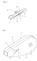
- Reference numeral 1 denotes an application tool made in accordance with the present invention.
- the application tool 1 has a cartridge body 2 installed detachably in a tool container or casing 9 of the application tool 1.
- the cartridge body 2 rotatably carries a supply reel gear 3 and a take-up reel gear 4 meshing with each other.
- a supply reel 5 and a take-up reel 6 are coaxially attached to the supply reel gear 3 or the take-up reel gear 4, respectively, for supplying and taking up a transfer tape 8.
- the transfer tape 8 is guided along a transfer head 7 protruding from one end of the container 9.
- the application tool container 9 has front and rear parts 10, 10.
- the front and rear parts 10, 10 can be connected with and separated from each other along a longitudinal plane laid through the application tool container 9.
- a slide plate 13 is provided and in slidable contact with a supporting portion 18 integral with a root portion 11 of the transfer head 7 for connecting the cartridge body 2 and the transfer head 7 with each other. End portions of the slide plate 13 extend in a direction towards each side face 12 of the application tool container 9 and project outwardly therefrom.
- An enlarged knob piece 17 is mounted to each end of the slide plate 13 and a locking aperture 14 comprising a large diameter portion 15 having a diameter larger than that of the knob piece 17 and a narrow groove portion 16 for guiding the slide plate 13 is provided in each side face 12 of the application tool container 9.
- the cartridge body 2 and the application tool container 9 can be freely attached to and detached from each other by sliding the slide plate 13 with respect to the locking apertures 14.
- the slide plate 13 adapted to slide on the supporting portion 18 of the transfer head 7 and extending through the application tool container 9 in such a manner so as to project from the side faces 12 of the application tool container 9 is held within the narrow groove portions 16 of the locking apertures 14, thereby the transfer head 7 is fixed to the application tool container 9 in a firm and stable manner.
- the application tool container 9 having therein the cartridge body 2 can readily be opened by sliding the slide plate 13 from the narrow groove portions 16 of the locking apertures 14 to the large diameter portions 15 thereof.
- the slide plate 13 does not disturb the user at a time of using the application tool 1.
- the slide plate 13 can have a center portion defined by side ridges with a distance from each other adapted to the width of the supporting portion 18 of the transfer head 7 so as to smoothly slide on the supporting portion 18, thereby the slide plate 13 can slide without laterally deviations relative to the supporting portion 18.
- the width of the narrow groove portions 16 and the thickness of the end portions of the slide plate 13 may be substantially equal to each other thereby closely fixing the narrow groove portions 16 and the slide plate 13 to each other, so that even when the user strongly grips the application tool container 9 at a time of using the application tool 1, the grip force applied to the application tool container 9 is supported both by the application tool container 9 and the cartridge body 2 installed within the application tool container 9. Accordingly, a deformation of the application tool container 9 is minimized, so that an inaccurate transfer and application of the medium due to a deformation of the application tool container 9 can be prevented.
- the application tool container of the application tool and the cartridge body installed in the application tool container are integrally and strongly fixed to each other during use, a swing motion of the transfer head generated at a time of closely attaching the transfer head to the surface of an object can be prevented, thereby solving the problems of breakage of the transfer tape and an interrupted application of the medium. Further, at a time of using the application tool, the slide plate does not disturb a smooth operation of the tool. Still further, since the application tool container and the cartridge body installed in the application tool container are integrally and strongly fixed to each other, the strength of the application tool container is improved, so that even when a user applies a strong force thereto a deformation of the application tool is effectively prevented.
Landscapes
- Adhesive Tape Dispensing Devices (AREA)
- Impression-Transfer Materials And Handling Thereof (AREA)
- Coating Apparatus (AREA)
Claims (1)
- Auftragsgerät (1) für ein Medium, umfassend einen Kassettenteil (2) mit einer drehbar daran montierten Vorratsspule (5) und Aufnahmespule (6), die miteinander antriebsmässig verknüpft sind, um ein Mediumübertragungsband (8) einem Übertragungskopf (7) zuzuführen und das Übertragungsband nach Führung längs des Übertragungskopfes aufzunehmen, und einen in einer longitudinalen Ebene verteilbaren Behälter (9), in dem in lösbarer Weise der Kassettenteil aufgenommen ist, dadurch gekennzeichnet, dass eine Gleitplatte (13) vorgesehen ist, die in Gleitberührung mit einem länglichen Stützbereich (18) des Übertragungskopfes (7) bringbar ist, der sich in Transportrichtung des Übertragungsbandes erstreckt, um den Übertragungskopf mit dem Kassettenteil zu verbinden, wobei die Gleitplatte Endbereiche hat, die sich von gegenüberliegenden Seitenflächen des Behälters erstrecken und an denen vergrösserte Endstücke (17) montiert sind, und dass Verriegelungsöffnungen (14) in den gegenüberliegenden Seitenflächen (12,12) des Behälters vorgesehen sind, um die Endbereiche der Gleitplatte aufzunehmen, wobei die Verriegelungsöffnungen Bereiche (15) mit einem Durchmesser, der grösser als der der Endstücke ist, und verengte Bereiche (16) aufweisen, um die Endbereiche der Gleitplatte aufzunehmen und zu führen, so dass wenn sich die Endstücke in einer Position der Gleitplatte in den Bereichen der Verriegelungsöffnungen mit dem grossen Durchmesser befinden, der Behälter geöffnet werden kann, und wenn sich die Endbereiche der Gleitplatte in einer anderen Position der Gleitplatte in den verengten Bereichen der Verriegelungsöffnungen befinden, der Behälter geschlossen ist.
Applications Claiming Priority (3)
| Application Number | Priority Date | Filing Date | Title |
|---|---|---|---|
| JP21122897A JP3505673B2 (ja) | 1997-07-23 | 1997-07-23 | 塗布具 |
| JP211228/97 | 1997-07-23 | ||
| JP21122897 | 1997-07-23 |
Publications (3)
| Publication Number | Publication Date |
|---|---|
| EP0893384A2 EP0893384A2 (de) | 1999-01-27 |
| EP0893384A3 EP0893384A3 (de) | 1999-04-21 |
| EP0893384B1 true EP0893384B1 (de) | 2001-11-28 |
Family
ID=16602415
Family Applications (1)
| Application Number | Title | Priority Date | Filing Date |
|---|---|---|---|
| EP98102078A Expired - Lifetime EP0893384B1 (de) | 1997-07-23 | 1998-02-06 | Werkzeug zum Anbringen eines Mediums |
Country Status (7)
| Country | Link |
|---|---|
| US (1) | US6059002A (de) |
| EP (1) | EP0893384B1 (de) |
| JP (1) | JP3505673B2 (de) |
| KR (1) | KR100313654B1 (de) |
| DE (1) | DE69802627T2 (de) |
| ES (1) | ES2167814T3 (de) |
| TW (1) | TW417608U (de) |
Families Citing this family (19)
| Publication number | Priority date | Publication date | Assignee | Title |
|---|---|---|---|---|
| US6321815B1 (en) * | 1999-09-24 | 2001-11-27 | Kwang-Ho You | Protector for leading end of correction tape |
| ES2182663B2 (es) * | 2000-11-07 | 2004-05-01 | Juan Antonio Campins Masriera | Dispensador de cinta correstora, adehesiva y similares. |
| US20040161564A1 (en) * | 2003-02-14 | 2004-08-19 | Truog Keith L. | Dry paint transfer laminate |
| US20040247837A1 (en) * | 2003-06-09 | 2004-12-09 | Howard Enlow | Multilayer film |
| US7204288B2 (en) * | 2003-06-10 | 2007-04-17 | The Procter & Gamble Company | Multi-burnish applicator for and method of applying a sheet material to a substrate |
| US6808586B1 (en) | 2003-06-10 | 2004-10-26 | The Procter & Gamble Company | Applicator for and method of applying a sheet material to a substrate |
| US6997229B2 (en) * | 2003-09-16 | 2006-02-14 | Sanford, L.P. | Rotatable applicator tip for a corrective tape dispenser |
| US20050056375A1 (en) * | 2003-09-16 | 2005-03-17 | Sanford, L.P. | Applicator tip for a corrective tape dispenser |
| US7540933B2 (en) * | 2003-11-04 | 2009-06-02 | The Procter & Gamble Company | Applicator for and method of applying a sheet material to a substrate |
| TWD121494S1 (zh) * | 2006-10-20 | 2008-02-21 | 蜻蜓鉛筆股份有限公司 | 塗膜轉印具用出帶頭 |
| TWD121495S1 (zh) * | 2006-10-20 | 2008-02-21 | 蜻蜓鉛筆股份有限公司 | 塗膜轉印具用保護蓋 |
| JP5332259B2 (ja) * | 2008-03-28 | 2013-11-06 | デクセリアルズ株式会社 | 異方性導電膜転写具及び接続方法 |
| US20100071853A1 (en) * | 2008-09-23 | 2010-03-25 | Chien-Lung Wu | Tape Dispenser |
| US8397784B2 (en) | 2010-08-31 | 2013-03-19 | Sanford, L.P. | Correction tape dispenser with variable clutch mechanism |
| US8746313B2 (en) | 2010-12-29 | 2014-06-10 | Sanford, L.P. | Correction tape re-tensioning mechanism and correction tape dispenser comprising same |
| US8578999B2 (en) | 2010-12-29 | 2013-11-12 | Sanford, L.P. | Variable clutch mechanism and correction tape dispenser with variable clutch mechanism |
| US8746316B2 (en) | 2011-12-30 | 2014-06-10 | Sanford, L.P. | Variable clutch mechanism and correction tape dispenser with variable clutch mechanism |
| JP6348345B2 (ja) * | 2014-06-12 | 2018-06-27 | プラス株式会社 | 塗布膜転写具 |
| FR3046786B1 (fr) | 2016-01-15 | 2018-02-09 | Societe Bic | Dispositif manuel d'application par ruban d'un revetement sur un support presentant un embout d'application ameliore |
Family Cites Families (11)
| Publication number | Priority date | Publication date | Assignee | Title |
|---|---|---|---|---|
| DE3736367C1 (de) * | 1987-10-27 | 1989-02-23 | Pelikan Ag | Handgeraet zum UEbertragen eines Filmes von einer Traegerfolie auf ein Substrat |
| EP0742111A3 (de) * | 1991-10-02 | 1997-09-24 | Fuji Kagaku Shikogyo | Übertragungsvorrichtung für Farbfilmen |
| DE4220843C1 (de) * | 1992-06-25 | 1993-08-05 | Citius Buerotechnik Gmbh, 8906 Gersthofen, De | |
| US5499877A (en) * | 1993-04-06 | 1996-03-19 | Fujicopian Co., Ltd. | Transfer ribbon cassette, a case for enclosing the cassette, and a paint film transfer device having the same |
| DE4322118C1 (de) * | 1993-07-02 | 1994-11-17 | Pelikan Ag | Handgerät zum Übertragen eines Films von einem Trägerband auf ein Substrat |
| DE9407305U1 (de) * | 1994-05-02 | 1994-09-22 | Czewo Plast Kunststofftechnik Gmbh, 93073 Neutraubling | Vorrichtung zur Abgabe von Auftrags-Material |
| JP3027309B2 (ja) * | 1994-12-12 | 2000-04-04 | シードゴム工業株式会社 | 塗膜転写具用テープカートリッジおよび塗膜転写具 |
| TW318812B (de) * | 1994-12-12 | 1997-11-01 | Yutoku Gum Kogyo Kk | |
| JPH08175094A (ja) * | 1994-12-21 | 1996-07-09 | General Kk | テープカートリッジ |
| JP3516188B2 (ja) * | 1995-10-27 | 2004-04-05 | 株式会社トンボ鉛筆 | 塗布具の転写テープ送出、巻取り部 |
| JPH11348493A (ja) * | 1998-06-08 | 1999-12-21 | Seed Rubber Kogyo Kk | 塗膜転写具用テープカートリッジおよび塗膜転写具 |
-
1997
- 1997-07-23 JP JP21122897A patent/JP3505673B2/ja not_active Expired - Fee Related
- 1997-10-09 TW TW089204999U patent/TW417608U/zh not_active IP Right Cessation
- 1997-12-30 KR KR1019970078550A patent/KR100313654B1/ko not_active Expired - Fee Related
-
1998
- 1998-02-06 DE DE69802627T patent/DE69802627T2/de not_active Expired - Lifetime
- 1998-02-06 EP EP98102078A patent/EP0893384B1/de not_active Expired - Lifetime
- 1998-02-06 ES ES98102078T patent/ES2167814T3/es not_active Expired - Lifetime
- 1998-07-23 US US09/122,039 patent/US6059002A/en not_active Expired - Fee Related
Also Published As
| Publication number | Publication date |
|---|---|
| JP3505673B2 (ja) | 2004-03-08 |
| JPH1134587A (ja) | 1999-02-09 |
| EP0893384A3 (de) | 1999-04-21 |
| US6059002A (en) | 2000-05-09 |
| TW417608U (en) | 2001-01-01 |
| EP0893384A2 (de) | 1999-01-27 |
| DE69802627D1 (de) | 2002-01-10 |
| HK1017330A1 (en) | 1999-11-19 |
| KR100313654B1 (ko) | 2001-12-28 |
| DE69802627T2 (de) | 2002-05-23 |
| KR19990013280A (ko) | 1999-02-25 |
| ES2167814T3 (es) | 2002-05-16 |
Similar Documents
| Publication | Publication Date | Title |
|---|---|---|
| EP0893384B1 (de) | Werkzeug zum Anbringen eines Mediums | |
| US5512128A (en) | Easy-load film applicator | |
| US5996231A (en) | Scraping tool with replaceable blade and controlled quick-release clamp | |
| EP1721852B1 (de) | Mittels eines Druckknopfes gesteuerte Korrekturbandrolle | |
| US7975745B2 (en) | Transfer tool | |
| US8297329B2 (en) | Coating film transfer tool | |
| US7866362B2 (en) | Transfer tool | |
| US10363764B2 (en) | Portable printer and methods | |
| HK1017330B (en) | Medium application tool | |
| JP2001015950A (ja) | 電気機器用電源アダプタ収納体 | |
| JP4246370B2 (ja) | 塗膜転写具 | |
| JP4316771B2 (ja) | 塗膜転写具 | |
| JP2002127682A (ja) | 修正テープや粘着テープ等の転写具 | |
| JP2002059692A (ja) | 修正テープや粘着テープ等の転写具 | |
| JP2006327037A (ja) | 塗膜転写具およびこれに用いるカートリッジ | |
| JP2000211799A (ja) | 転写テ―プケ―ス | |
| JP2006051663A (ja) | カバー付きディスペンサー | |
| US5209586A (en) | Ribbon cartridge and printer drive system for the ribbon | |
| JPH0424804Y2 (de) | ||
| JP2525195Y2 (ja) | リボンカセット保持装置 | |
| JP4750885B2 (ja) | カバー付きディスペンサー | |
| JP3386905B2 (ja) | テープカートリッジ及び転写具 | |
| JP4750887B2 (ja) | カバー付きディスペンサー | |
| JP2523561Y2 (ja) | ラベル貼付機におけるラベルカセットの保持装置 | |
| JP2010069888A (ja) | カバー付きディスペンサー |
Legal Events
| Date | Code | Title | Description |
|---|---|---|---|
| PUAI | Public reference made under article 153(3) epc to a published international application that has entered the european phase |
Free format text: ORIGINAL CODE: 0009012 |
|
| AK | Designated contracting states |
Kind code of ref document: A2 Designated state(s): DE ES FR GB IT |
|
| AX | Request for extension of the european patent |
Free format text: AL;LT;LV;MK;RO;SI |
|
| PUAL | Search report despatched |
Free format text: ORIGINAL CODE: 0009013 |
|
| AK | Designated contracting states |
Kind code of ref document: A3 Designated state(s): AT BE CH DE DK ES FI FR GB GR IE IT LI LU MC NL PT SE |
|
| AX | Request for extension of the european patent |
Free format text: AL;LT;LV;MK;RO;SI |
|
| 17P | Request for examination filed |
Effective date: 19990430 |
|
| AKX | Designation fees paid |
Free format text: DE ES FR GB IT |
|
| GRAG | Despatch of communication of intention to grant |
Free format text: ORIGINAL CODE: EPIDOS AGRA |
|
| GRAG | Despatch of communication of intention to grant |
Free format text: ORIGINAL CODE: EPIDOS AGRA |
|
| GRAH | Despatch of communication of intention to grant a patent |
Free format text: ORIGINAL CODE: EPIDOS IGRA |
|
| 17Q | First examination report despatched |
Effective date: 20010226 |
|
| GRAH | Despatch of communication of intention to grant a patent |
Free format text: ORIGINAL CODE: EPIDOS IGRA |
|
| GRAA | (expected) grant |
Free format text: ORIGINAL CODE: 0009210 |
|
| AK | Designated contracting states |
Kind code of ref document: B1 Designated state(s): DE ES FR GB IT |
|
| REG | Reference to a national code |
Ref country code: GB Ref legal event code: IF02 |
|
| REF | Corresponds to: |
Ref document number: 69802627 Country of ref document: DE Date of ref document: 20020110 |
|
| REG | Reference to a national code |
Ref country code: ES Ref legal event code: FG2A Ref document number: 2167814 Country of ref document: ES Kind code of ref document: T3 |
|
| PLBE | No opposition filed within time limit |
Free format text: ORIGINAL CODE: 0009261 |
|
| STAA | Information on the status of an ep patent application or granted ep patent |
Free format text: STATUS: NO OPPOSITION FILED WITHIN TIME LIMIT |
|
| 26N | No opposition filed | ||
| PGFP | Annual fee paid to national office [announced via postgrant information from national office to epo] |
Ref country code: ES Payment date: 20100219 Year of fee payment: 13 |
|
| PGFP | Annual fee paid to national office [announced via postgrant information from national office to epo] |
Ref country code: IT Payment date: 20100227 Year of fee payment: 13 Ref country code: FR Payment date: 20100315 Year of fee payment: 13 |
|
| PGFP | Annual fee paid to national office [announced via postgrant information from national office to epo] |
Ref country code: GB Payment date: 20100219 Year of fee payment: 13 Ref country code: DE Payment date: 20100226 Year of fee payment: 13 |
|
| GBPC | Gb: european patent ceased through non-payment of renewal fee |
Effective date: 20110206 |
|
| REG | Reference to a national code |
Ref country code: FR Ref legal event code: ST Effective date: 20111102 |
|
| PG25 | Lapsed in a contracting state [announced via postgrant information from national office to epo] |
Ref country code: IT Free format text: LAPSE BECAUSE OF NON-PAYMENT OF DUE FEES Effective date: 20110206 |
|
| REG | Reference to a national code |
Ref country code: DE Ref legal event code: R119 Ref document number: 69802627 Country of ref document: DE Effective date: 20110901 |
|
| PG25 | Lapsed in a contracting state [announced via postgrant information from national office to epo] |
Ref country code: FR Free format text: LAPSE BECAUSE OF NON-PAYMENT OF DUE FEES Effective date: 20110228 |
|
| PG25 | Lapsed in a contracting state [announced via postgrant information from national office to epo] |
Ref country code: GB Free format text: LAPSE BECAUSE OF NON-PAYMENT OF DUE FEES Effective date: 20110206 |
|
| REG | Reference to a national code |
Ref country code: ES Ref legal event code: FD2A Effective date: 20120411 |
|
| PG25 | Lapsed in a contracting state [announced via postgrant information from national office to epo] |
Ref country code: ES Free format text: LAPSE BECAUSE OF NON-PAYMENT OF DUE FEES Effective date: 20110207 |
|
| PG25 | Lapsed in a contracting state [announced via postgrant information from national office to epo] |
Ref country code: DE Free format text: LAPSE BECAUSE OF NON-PAYMENT OF DUE FEES Effective date: 20110901 |