EP0893389A2 - Dispositif d'accrochage pour appareils de levage, en particulier pour prendre ou déposer des capots d'isolation thermique - Google Patents
Dispositif d'accrochage pour appareils de levage, en particulier pour prendre ou déposer des capots d'isolation thermique Download PDFInfo
- Publication number
- EP0893389A2 EP0893389A2 EP98112859A EP98112859A EP0893389A2 EP 0893389 A2 EP0893389 A2 EP 0893389A2 EP 98112859 A EP98112859 A EP 98112859A EP 98112859 A EP98112859 A EP 98112859A EP 0893389 A2 EP0893389 A2 EP 0893389A2
- Authority
- EP
- European Patent Office
- Prior art keywords
- pair
- lever arms
- heat insulation
- crossmember
- hook
- Prior art date
- Legal status (The legal status is an assumption and is not a legal conclusion. Google has not performed a legal analysis and makes no representation as to the accuracy of the status listed.)
- Withdrawn
Links
- 238000010168 coupling process Methods 0.000 title claims abstract description 16
- 230000008878 coupling Effects 0.000 title claims abstract description 15
- 238000005859 coupling reaction Methods 0.000 title claims abstract description 15
- 238000000151 deposition Methods 0.000 title claims abstract 3
- 238000009413 insulation Methods 0.000 claims abstract description 27
- 239000000725 suspension Substances 0.000 claims description 4
- 238000013459 approach Methods 0.000 description 2
- 230000015572 biosynthetic process Effects 0.000 description 1
- 238000010276 construction Methods 0.000 description 1
- 238000000034 method Methods 0.000 description 1
Images
Classifications
-
- B—PERFORMING OPERATIONS; TRANSPORTING
- B66—HOISTING; LIFTING; HAULING
- B66C—CRANES; LOAD-ENGAGING ELEMENTS OR DEVICES FOR CRANES, CAPSTANS, WINCHES, OR TACKLES
- B66C1/00—Load-engaging elements or devices attached to lifting or lowering gear of cranes or adapted for connection therewith for transmitting lifting forces to articles or groups of articles
- B66C1/10—Load-engaging elements or devices attached to lifting or lowering gear of cranes or adapted for connection therewith for transmitting lifting forces to articles or groups of articles by mechanical means
- B66C1/62—Load-engaging elements or devices attached to lifting or lowering gear of cranes or adapted for connection therewith for transmitting lifting forces to articles or groups of articles by mechanical means comprising article-engaging members of a shape complementary to that of the articles to be handled
- B66C1/66—Load-engaging elements or devices attached to lifting or lowering gear of cranes or adapted for connection therewith for transmitting lifting forces to articles or groups of articles by mechanical means comprising article-engaging members of a shape complementary to that of the articles to be handled for engaging holes, recesses, or abutments on articles specially provided for facilitating handling thereof
Definitions
- the invention relates to a hanging coupling on lifting devices, esp. for picking up and setting down heat insulation hoods from and above Wire bundles.
- Thermal insulation hoods such as those behind continuous high-performance wire rod mills used to make that out of one another Wire loops in quick succession, still hot wire bundles to isolate before transporting them, have been used by Crane trolleys or similar lifting devices with the help of these usual harnesses gripped and coupled and then over the bundles of wire lowered, and then, after uncoupling the dishes, transported on.
- the coupling or uncoupling process the thermal insulation hood with the hanging gear required
- Experience of the operating personnel and also relatively much Time since the top of the heat insulation hood depending on the construction and functioning of the institutions for federal formation more or less accessible and also the radiant heat of the hot Bunde makes working difficult.
- the object of the invention is to overcome these difficulties eliminate and also the time and manpower in the clutch and uncoupling of the hanging gear with the heat insulation hoods reduce.
- each Traverse double-armed lever pairs can be pivoted to each other in mirror image are articulated, one of a pair of lever arms above the Traverse is connected to the lifting device via handlebars, and their other pair of lever arms, hook-shaped below the crossbar Has ends by one, from the stroke of the handlebars to the Lever pair transmitted train movement swiveled towards each other, with support lugs arranged on the top of the heat insulation hood are detachable, and that on the crossbar and the upper pair of lever arms opposite each other electric traction magnets and, these associated anchors are arranged in the switch-on pull position lock the upper pair of lever arms with the crossbar and opposite the hook-shaped ends of the lower pair of lever arms the carrying lugs of the thermal insulation hood out of the coupling position hold.
- alignment elements be arranged when the crossbar is placed on the heat insulation hood releasably interlock.
- These alignment elements can from, arranged on the underside of the traverse, directed downwards wedge-shaped approaches and corresponding, open to the top Wedge depressions and, if necessary, inclined funnel-shaped sides
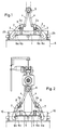
- a crossbar 1 is located at both ends the two-armed levers 2 of a pair of levers articulated with steering bearings 3.
- the ends of the upper pair of lever arms 2a, above the crossbar 1 are articulated via handlebars 4 with the lifting device 5 connected.
- the ends of the lower pair of lever arms 2b are hook-shaped educated. You are opposite approaches 6a, which on the Thermal insulation hood 6 are arranged.
- Pull magnets 7 are on the top of the cross member 1 (see FIG. 2) arranged, which are arranged below the upper pair of lever arms 2a Anchor 8 are assigned. Furthermore, in the area of the support lugs 6a on the top of the heat insulation hood 6 support latches 6b for the Place the crossbar 1 and lateral, funnel-shaped incline Guide plates 10 and wedge depressions 9 open at the top are provided.
- the hitch works in such a way that it works with the help of Lifting device 5 in the position shown in FIG Double arm lever 2 with the pull magnet 7 switched on on the top the heat insulation hood 6 is lowered, the crossbar opening the bearing catches 6b on the top of the heat insulation hood 6 hangs up.
- the hook-shaped ends of the lower pair of lever arms 2b lie opposite the support lugs 6a.
- the orientation of the Traverse 1 in this position takes place via the guide plates mentioned 9 or wedge depressions 10, in corresponding (not here shown) engage elements on crossbar 1.
- the ends of the lower pairs of lever arms 2b being the support lugs 6a and thus the coupling between the crossbar 1 and the heat insulation hood 6.
- the double arm levers move through the so-called slack rope effect back to each other in the position shown in FIG. 1 and can then held in this position by switching on the magnets 7 to initiate another coupling process.
Landscapes
- Engineering & Computer Science (AREA)
- Mechanical Engineering (AREA)
- Load-Engaging Elements For Cranes (AREA)
- Metal Rolling (AREA)
- Winding, Rewinding, Material Storage Devices (AREA)
Applications Claiming Priority (2)
| Application Number | Priority Date | Filing Date | Title |
|---|---|---|---|
| DE29712552U | 1997-07-16 | ||
| DE29712552U DE29712552U1 (de) | 1997-07-16 | 1997-07-16 | Hängekupplung für Hubvorrichtungen, insbesondere für das Aufnehmen und Absetzen von Wärme-Isolierhauben |
Publications (2)
| Publication Number | Publication Date |
|---|---|
| EP0893389A2 true EP0893389A2 (fr) | 1999-01-27 |
| EP0893389A3 EP0893389A3 (fr) | 2000-12-20 |
Family
ID=8043182
Family Applications (1)
| Application Number | Title | Priority Date | Filing Date |
|---|---|---|---|
| EP98112859A Withdrawn EP0893389A3 (fr) | 1997-07-16 | 1998-07-11 | Dispositif d'accrochage pour appareils de levage, en particulier pour prendre ou déposer des capots d'isolation thermique |
Country Status (4)
| Country | Link |
|---|---|
| US (1) | US6039374A (fr) |
| EP (1) | EP0893389A3 (fr) |
| JP (1) | JPH1177155A (fr) |
| DE (1) | DE29712552U1 (fr) |
Cited By (1)
| Publication number | Priority date | Publication date | Assignee | Title |
|---|---|---|---|---|
| US6257636B1 (en) | 2000-06-02 | 2001-07-10 | The United States Of America As Represented By The United States Department Of Energy | Self-actuating mechanical grapple for lifting and handling objects |
Families Citing this family (8)
| Publication number | Priority date | Publication date | Assignee | Title |
|---|---|---|---|---|
| FR2854393B1 (fr) * | 2003-04-30 | 2005-06-17 | Potain Sa | Dispositif de lestage pour grue |
| US8297652B2 (en) * | 2009-01-13 | 2012-10-30 | Tk Holdings, Inc. | Gas generating system |
| CN107545989B (zh) * | 2017-08-28 | 2019-08-09 | 陈海陆 | 一种变压器安装抬升装置 |
| US10603800B1 (en) * | 2018-03-13 | 2020-03-31 | Amazon Technologies, Inc. | Gripper having a four bar linkage |
| US12122014B2 (en) * | 2020-07-23 | 2024-10-22 | Changxin Memory Technologies, Inc. | Replacing tool for sponge brush, method for installing sponge brush, and semiconductor chemical mechanical polishing apparatus |
| CN112723134B (zh) * | 2020-12-18 | 2022-05-03 | 四川宏华石油设备有限公司 | 一种机械式水下设备吊装连接机构 |
| CN113399467B (zh) * | 2021-06-18 | 2023-06-27 | 广东韶钢松山股份有限公司 | 一种立式轧辊万向轴安全装置及使用方法 |
| US20240155796A1 (en) * | 2022-11-07 | 2024-05-09 | International Business Machines Corporation | Cold plate placement and retraction apparatus with predefined travel pathway |
Family Cites Families (11)
| Publication number | Priority date | Publication date | Assignee | Title |
|---|---|---|---|---|
| CA768524A (en) * | 1967-10-03 | Russell T. Flora, Jr. | Lifting hook assembly | |
| US1630456A (en) * | 1925-08-25 | 1927-05-31 | Cleveland Crane Eng | Grab |
| US1957719A (en) * | 1933-04-06 | 1934-05-08 | Rotary Steel Company | Lifting device |
| US3257142A (en) * | 1960-03-25 | 1966-06-21 | Leonard D Barry | Material handling system |
| US3306646A (en) * | 1965-07-30 | 1967-02-28 | Flexicore Company Inc | Lifting hook assembly |
| SU630191A1 (ru) * | 1977-05-17 | 1978-10-30 | Всесоюзный Государственный Проектный Институт По Строительному Машиностроению Для Сборного Железобетона "Гипростроммаш" | Захватное устройство |
| SU1136935A1 (ru) * | 1982-06-07 | 1985-01-30 | Ворошиловградский машиностроительный институт | Захват манипул тора |
| DE3329646C1 (de) * | 1983-08-17 | 1984-11-15 | Kernforschungszentrum Karlsruhe Gmbh, 7500 Karlsruhe | Greifer zum Erfassen von wahlweise mit oder ohne Pilzdeckel versehenen Rollreifenfässern |
| SU1449510A1 (ru) * | 1987-02-25 | 1989-01-07 | Предприятие П/Я М-5292 | Грузозахватное устройство |
| SU1576466A1 (ru) * | 1988-06-29 | 1990-07-07 | Государственный Проектно-Конструкторский И Технологический Институт "Индустройпроект" | Механизм фиксации автоматического захватного устройства |
| SU1720986A1 (ru) * | 1989-02-20 | 1992-03-23 | В.А.Трапезников, В.И.Ефимов и С.М.Колганов | Грузозахватное устройство |
-
1997
- 1997-07-16 DE DE29712552U patent/DE29712552U1/de not_active Expired - Lifetime
-
1998
- 1998-07-11 EP EP98112859A patent/EP0893389A3/fr not_active Withdrawn
- 1998-07-14 JP JP10198930A patent/JPH1177155A/ja not_active Withdrawn
- 1998-07-15 US US09/115,801 patent/US6039374A/en not_active Expired - Fee Related
Cited By (1)
| Publication number | Priority date | Publication date | Assignee | Title |
|---|---|---|---|---|
| US6257636B1 (en) | 2000-06-02 | 2001-07-10 | The United States Of America As Represented By The United States Department Of Energy | Self-actuating mechanical grapple for lifting and handling objects |
Also Published As
| Publication number | Publication date |
|---|---|
| EP0893389A3 (fr) | 2000-12-20 |
| US6039374A (en) | 2000-03-21 |
| JPH1177155A (ja) | 1999-03-23 |
| DE29712552U1 (de) | 1997-10-02 |
Similar Documents
| Publication | Publication Date | Title |
|---|---|---|
| DE19809331C1 (de) | Verfahr- und arretierbare Sammelvorrichtung | |
| CH662164A5 (de) | Vorrichtung zum fuehren von flexiblen versorgungsleitungen. | |
| EP0893389A2 (fr) | Dispositif d'accrochage pour appareils de levage, en particulier pour prendre ou déposer des capots d'isolation thermique | |
| DE2422135B2 (de) | Vorrichtung zum manipulieren eines kernreaktor-brennelements in einem wasser enthaltenden brennelementlagerbecken | |
| DE10116216A1 (de) | Vorrichtung zum Bewegen einer an einem Tragarm schwenkbar gelagerten Flugzeugtür | |
| DE2100570C3 (de) | Schleppkreisförderer | |
| DE102014015963B4 (de) | Gerüstwechselsystem, Wechselwagen und Weiche für ein Gerüstwechselsystem und Walzwerk mit einem Walzblock und einem Gerüstwechselsystem | |
| EP3695991B1 (fr) | Système de train routier ou convoi remorqué | |
| EP3453587A1 (fr) | Dispositif d'accouplement sur chariot de nettoyage | |
| DE19620068C1 (de) | Kupplungsanordnung für Schienenfahrzeuge, insbesondere Rangierlokomotiven | |
| DE1759525A1 (de) | Hebevorrichtung fuer Gleitschalungen bei der Herstellung von Betonbauteilen mit mindestens einer schraegen Wandflaeche | |
| DE102013210372A1 (de) | Vorrichtung zum Transport | |
| DE2617255C3 (de) | Anlage zum Handhaben von Gußformen | |
| DE2815808A1 (de) | Foerdersystem | |
| DE1804775C3 (de) | Abnahmevorrichtung in Art einer Weiche für das Umspuren der Traghaken von Anhängebügeln | |
| EP0864670A2 (fr) | Appareil de levage pour un appareil de tirage de cristaux | |
| DE3200255A1 (de) | "starteinrichtung in maschinen fuer kontinuierlichen guss" | |
| EP3153345B1 (fr) | System de maintien de corde de support et fils pour catenaire | |
| DE1207584B (de) | Auf einem Laufkran angeordnete Winde mit zwei Trommeln | |
| DE512063C (de) | Schrotpaketgreifer | |
| EP1486278A1 (fr) | Manupulateur d'une pache d'une machine de coulée | |
| DE740848C (de) | Fahrzeugselbstkupplung, insbesondere fuer Foerderwagen | |
| DE809761C (de) | Schwerlastfahrzeug mit tiefliegender Ladeflaeche | |
| DE2232816A1 (de) | Selbstschliessender zangengreifer | |
| DE3408798C2 (de) | Aus zwei durch Schlauchleitungen untereinander flexibel medienverbundenen Mehrfachkupplungen bestehendes Anschlußsystem |
Legal Events
| Date | Code | Title | Description |
|---|---|---|---|
| PUAI | Public reference made under article 153(3) epc to a published international application that has entered the european phase |
Free format text: ORIGINAL CODE: 0009012 |
|
| 17P | Request for examination filed |
Effective date: 19980711 |
|
| AK | Designated contracting states |
Kind code of ref document: A2 Designated state(s): AT DE IT SE |
|
| AX | Request for extension of the european patent |
Free format text: AL;LT;LV;MK;RO;SI |
|
| RAP1 | Party data changed (applicant data changed or rights of an application transferred) |
Owner name: SMS DEMAG AG |
|
| PUAL | Search report despatched |
Free format text: ORIGINAL CODE: 0009013 |
|
| AK | Designated contracting states |
Kind code of ref document: A3 Designated state(s): AT BE CH CY DE DK ES FI FR GB GR IE IT LI LU MC NL PT SE |
|
| AX | Request for extension of the european patent |
Free format text: AL;LT;LV;MK;RO;SI |
|
| AKX | Designation fees paid |
Free format text: AT DE IT SE |
|
| 17Q | First examination report despatched |
Effective date: 20040528 |
|
| GRAP | Despatch of communication of intention to grant a patent |
Free format text: ORIGINAL CODE: EPIDOSNIGR1 |
|
| RTI1 | Title (correction) |
Free format text: THERMALLY INSULATED COVER AND LIFTING DEVICE THEREFOR |
|
| STAA | Information on the status of an ep patent application or granted ep patent |
Free format text: STATUS: THE APPLICATION IS DEEMED TO BE WITHDRAWN |
|
| 18D | Application deemed to be withdrawn |
Effective date: 20050906 |