EP0893396A1 - Rotationsfüller mit aseptischer Füllkammer - Google Patents
Rotationsfüller mit aseptischer Füllkammer Download PDFInfo
- Publication number
- EP0893396A1 EP0893396A1 EP98112200A EP98112200A EP0893396A1 EP 0893396 A1 EP0893396 A1 EP 0893396A1 EP 98112200 A EP98112200 A EP 98112200A EP 98112200 A EP98112200 A EP 98112200A EP 0893396 A1 EP0893396 A1 EP 0893396A1
- Authority
- EP
- European Patent Office
- Prior art keywords
- wall
- filling
- rotary filler
- filler according
- clean room
- Prior art date
- Legal status (The legal status is an assumption and is not a legal conclusion. Google has not performed a legal analysis and makes no representation as to the accuracy of the status listed.)
- Granted
Links
Images

Classifications
-
- B—PERFORMING OPERATIONS; TRANSPORTING
- B67—OPENING, CLOSING OR CLEANING BOTTLES, JARS OR SIMILAR CONTAINERS; LIQUID HANDLING
- B67C—CLEANING, FILLING WITH LIQUIDS OR SEMILIQUIDS, OR EMPTYING, OF BOTTLES, JARS, CANS, CASKS, BARRELS, OR SIMILAR CONTAINERS, NOT OTHERWISE PROVIDED FOR; FUNNELS
- B67C3/00—Bottling liquids or semiliquids; Filling jars or cans with liquids or semiliquids using bottling or like apparatus; Filling casks or barrels with liquids or semiliquids
- B67C3/02—Bottling liquids or semiliquids; Filling jars or cans with liquids or semiliquids using bottling or like apparatus
-
- B—PERFORMING OPERATIONS; TRANSPORTING
- B67—OPENING, CLOSING OR CLEANING BOTTLES, JARS OR SIMILAR CONTAINERS; LIQUID HANDLING
- B67C—CLEANING, FILLING WITH LIQUIDS OR SEMILIQUIDS, OR EMPTYING, OF BOTTLES, JARS, CANS, CASKS, BARRELS, OR SIMILAR CONTAINERS, NOT OTHERWISE PROVIDED FOR; FUNNELS
- B67C7/00—Concurrent cleaning, filling, and closing of bottles; Processes or devices for at least two of these operations
- B67C7/0073—Sterilising, aseptic filling and closing
-
- B—PERFORMING OPERATIONS; TRANSPORTING
- B67—OPENING, CLOSING OR CLEANING BOTTLES, JARS OR SIMILAR CONTAINERS; LIQUID HANDLING
- B67C—CLEANING, FILLING WITH LIQUIDS OR SEMILIQUIDS, OR EMPTYING, OF BOTTLES, JARS, CANS, CASKS, BARRELS, OR SIMILAR CONTAINERS, NOT OTHERWISE PROVIDED FOR; FUNNELS
- B67C3/00—Bottling liquids or semiliquids; Filling jars or cans with liquids or semiliquids using bottling or like apparatus; Filling casks or barrels with liquids or semiliquids
- B67C3/02—Bottling liquids or semiliquids; Filling jars or cans with liquids or semiliquids using bottling or like apparatus
- B67C3/22—Details
- B67C3/26—Filling-heads; Means for engaging filling-heads with bottle necks
- B67C2003/2688—Means for filling containers in defined atmospheric conditions
- B67C2003/2691—Means for filling containers in defined atmospheric conditions by enclosing one container in a chamber
Definitions
- the invention relates to a rotary filler for filling of liquids, especially beverages, in vessels, especially bottles, under high purity filling conditions, with a variety of distributed around the circumference of a rotor arranged filling valves with holding elements for cooling the Vessels under the filling valves during circulation and with one in the area of the bottle orbit with an inner wall, an outer wall, a ceiling wall and a bottom wall delimited clean room in which by introducing high purity gas, e.g. sterile air, a high purity Atmosphere is maintained during the filling process.
- high purity gas e.g. sterile air
- a filler that is intended for this type of filling is in European application 405 402.
- This Filling machine is designed as a rotary filler. She points Filling valves distributed around the circumference. Bottles are held under the filling valves with holding elements, those in a delimited, clean room Run around the area of the filler.
- the clean room is through corresponding walls, namely an inner wall, an outer wall, bounded by a ceiling wall and a floor wall.
- the ceiling wall is from an upper filler plate and the bottom wall from a lower filler plate. Between the two The inner wall runs panels.
- the stationary outer wall on the other hand forms towards the ceiling wall and the floor wall Slots through which in the so limited space injected sterile air can escape.
- the sterile air is from the ceiling plate around the filling valve into the Clean room initiated.
- the bottles are in that Clean room on the base plate and be on the side Holding elements held, but no vertical movement of the Allow bottles. Because the filler through the ceiling wall is passed through and via a line with the above of the filler arranged in connection and the actual filling valve outside the clean room is arranged, there is a risk that over the length of the Connecting line and the elements connected to it, like filling valve and flow meter, germs during the filling process be entered in the clean room.
- the invention is based on this prior art the problem of specifying a rotary filler with which maintain high-purity bottling conditions can, at the same time the construction if possible should be easy.
- the upper limit of the clean room Ceiling wall at least partially from the bottom of a ring tank and the liquid to be filled filling valves arranged immediately below the filling valves themselves are in the clean room and it is a direct feed from the ring bowl to the filling valves possible so that the liquid to be filled on the shortest Bottled away without the risk of contamination from germs can be.
- the fact that the bottom of the ring bowl to Part of it forms the upper ceiling wall also a constructive simplification. Overall creates the combination of these features thus the possibility at simple construction to a high-purity filling process guarantee.
- that part of the ceiling wall from one of the ring kettles supporting plate is formed. Be through this part then preferred drive rods as part of the drive elements passed through for the holding elements.
- this Drive rods by at least the lifting height in length corresponding sleeves are guided.
- the Sleeve that surrounds the drive rod creates one there Space in which the sterile air atmosphere prevails. If the Length of the sleeve corresponds at least to the lifting height this is that part of the drive rod that is raised in Condition outside the sleeve, still when lowering remains in the area of the sleeve, so that the Outside atmosphere no germs in the interior of the clean room can also be entered with the holding elements lowered.
- the outer wall and preferably also the bottom wall a support frame are arranged so that if necessary allow access to the clean room. Access can for example, by allowing the outer wall and / or the bottom wall is divided into individual segments, which are each arranged on hinges on the support frame are, so that when there is access to the clean interior the outer wall is required at the appropriate point can be opened. The same can of course also be done reach when the outer wall total of the support frame is removably arranged. Turn the bottom wall and outer wall not with the fountain pen, but from the Supported frame and allow one if necessary Access. On the other hand, the part turns from the bottom of the Ring bowl formed ceiling wall and the inner wall with the Rotary filler rotor with.
- the sterile gas entry into the clean room through the side in Area of the outer wall provided gas inlet openings he follows. These gas inlet openings can at the Side wall can be provided in several places, so that even gas entry is possible.
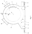
- the rotary filler 1 shows a schematic plan view of the basic structure of the invention Rotary filler 1.
- the rotary filler 1 comprises a rotor 2, on the circumference evenly distributed a variety of Filling valves 3 are arranged.
- the filling valves open the orbit 4 when the rotor 2 is driven about the axis 11 around.
- the circulation bottles 18, which are among the Filling valves 3 are kept (see FIG. 2), filled.
- the bottles 18 are on a conveyor belt 5 and one Transfer star 9 to the rotor 2 in a known manner. After the circulation, the bottles 18 are transferred from the transfer star 7 handed over to a closer 8. After closing the bottles 18 are taken over by an outlet star 9 and placed on a conveyor belt 10 from where they are to to the next ward for further treatment.
- the outer wall 12 and the bottom wall 14 is over a Supported frame 28, the support 30 distributed around the circumference has, and arms 29 branching therefrom, which inwards run towards the rotor axis and the lower support plate 31 of the rotor 2 rotatably supported on a slewing ring which fixes the inner wall 13 supporting the upper plate 17 is.
- the outer wall 12 can be distributed over the circumference in individual segments can be divided, each of which e.g. can be opened via hinges so that access in the clean room is possible.
- too Bottom wall 14 can be removed or swung away accordingly.
- the bottles 18, in the exemplary embodiment shown PET plastic bottles, are of holding elements 27 to the Outlet mouth of the filling valve 3 pressed.
- Each Holding element 27 is opened and closed via drive elements 21 crazy. So it takes a bottle 18 at the bottle inlet from a lower position and spends it in the Figure 2 shown position immediately at the outlet end of the filling valve 3.
- the Drive elements 21 lowered the bottle 18 again.
- the Drive elements 21 include drive rods 20, the Linkage 24, the gas spring 25, the scanning roller 23 and the Control curve 22.
- the control curve 22 is fixed within the rotating parts of the rotor 2 arranged and causes over the scanning roller 23 in connection with the upward acting gas spring 25 lifting and lowering the linkage 24, so that the drive rods 20 and the Holding elements 27 from the inside of the wall 13 and the Rotors 2 are controlled here.
- bushings are created in the form of sleeves 26 through which the drive rods 20 pass through.
- the length 1 this sleeve 26 is dimensioned so that it is at least the Lifting height of the linkage 21 corresponds, so that in the position shown outside the sleeve 26 upper Part of the drive rods 20 still inside after lowering the sleeve 26 remains and therefore not such germs entered into the interior of the clean room 19 when lowering that may be due to the not in the clean room have deposited upper part of the drive rods 20.
- the actual filling process runs in a manner known per se from.
- the individual filling valves 3 and additional control valves 37 in a suitable manner pressurized to introduce purge gas, the return gas outlet control, open the liquid valve, and the like.
- the side of the Sterile air supply openings 34 arranged on outer wall 12 sterile air is constantly blown into the clean room 19.
- This Sterile air can pass through an air outlet slot 32 Bottom wall 14 and inner wall 13 on the one hand and by one Air outlet slot 33 between the outer wall 12 and the Underside 15 of the ring bowl 16 emerge on the other hand, so that the clean room 19 is constantly flushed.
- the bottle 18 Since the bottle 18 is held directly on the filling valve 3 arranged on the ring bowl 16 with holding elements 27 and the paths of the liquid into the bottle 18 are very short, a high-purity atmosphere is maintained in the area of the actual filling process without the risk of germ entry.
- the sterile air constantly flows around the outlet opening of the filling valve 3, as does the bottle neck, so that a filling process can be maintained and carried out under highly pure conditions (up to less than 100 germs per m 3 are possible).
- Characterized in that the drive elements for the holding elements 27 are located outside the clean room 19 towards the rotor axis and only engage with drive rods 20 in the clean room 19 itself in order to raise and lower the holding elements 27, which can be holding clips, for example, the clean room remains 19 altogether largely free of internals.
- the drive from the inside also keeps the possibility of free access from the outside when the wall 12 is removed or opened.
Landscapes
- Filling Of Jars Or Cans And Processes For Cleaning And Sealing Jars (AREA)
- Vacuum Packaging (AREA)
- Compositions Of Macromolecular Compounds (AREA)
- Polishing Bodies And Polishing Tools (AREA)
- Centrifugal Separators (AREA)
- Basic Packing Technique (AREA)
- Materials For Medical Uses (AREA)
Abstract
Description
- Figur 1
- eine schematische Draufsicht auf einen erfindungsgemäßen Rotationsfüller und
- Figur 2
- Schnittansicht entlang der Linie II-II der Figur 1.
Claims (10)
- Rotationsfüller zum Abfüllen von Flüssigkeiten, insbesondere Getränken, in Gefäße, insbesondere Flaschen, unter hochreinen Abfüllbedingungen, mit einer Vielzahl von am Umfang eines Rotors angeordneten Füllventilen, Halteelementen zum Halten der Gefäße unter den Füllventilen während des Umlaufs und mit einem im Bereich der Flaschenumlaufbahn mit einer Innenwand, einer Außenwand, einer Deckenwand und einer Bodenwand abgegrenzten Reinstraum, in dem durch Einleiten von hochreinem Gas, z.B. steriler Luft, eine hochreine Atmosphäre während des Abfüllvorgangs aufrechterhalten wird, dadurch gekennzeichnet, dass die den Reinstraum (19) nach oben hin begrenzende Deckenwand zumindestens teilweise von der Unterseite (15) eines die abzufüllende Flüssigkeit (36) speichernden Ringkessels (16) und der unmittelbar darunter angeordneten Füllventile (3) gebildet wird.
- Rotationsfüller nach Anspruch 1, dadurch gekennzeichnet, dass ein Teil der Deckenwand von einer den Ringkessel (16) tragenden Platte (17) des Rotors (2) gebildet wird.
- Rotationsfüller nach Anspruch 1 oder 2, dadurch gekennzeichnet, dass Antriebsstangen (20) der Halteelemente (27) durch die Deckenwand hindurchgeführt sind.
- Rotationsfüller nach Anspruch 3, dadurch gekennzeichnet, dass die Antriebsstangen(20) durch den von der Platte (17) gebildeten Teil der Deckenwand hindurchgeführt sind.
- Rotationsfüller nach Anspruch 3 oder 4, dadurch gekennzeichnet, dass die Antriebsstangen (20) durch in ihrer Länge (1) wenigstens der Hubhöhe der Halteelemente (27) entsprechende Hülsen (26) geführt sind.
- Rotationsfüller nach wenigstens einem der vorangehenden Ansprüche, dadurch gekennzeichnet, dass die stationäre Außenwand (12) und vorzugsweise auch die stationäre Bodenwand (14) derart an einem Traggestell (28) angeordnet sind, dass sie im Bedarfsfall einen Zugang zum Reinstraum (19) ermöglichen.
- Rotationsfüller nach wenigstens einem der vorangehenden Ansprüche, dadurch gekennzeichnet, dass zwischen der Bodenwand (14) und der Innenwand (13) ein Luftaustrittsschlitz (32) vorgesehen ist.
- Rotationsfüller nach wenigstens einem der vorangehenden Ansprüche, dadurch gekennzeichnet, dass zwischen der Außenwand (12) und der Deckenwand ein Luftaustrittsschlitz (33) vorgesehen ist.
- Rotationsfüller nach wenigstens einem der vorangehenden Ansprüche, dadurch gekennzeichnet, dass der Sterilgaseintritt in den Reinstraum (19) durch seitliche, im Bereich der Außenwand (12) vorgesehene Gaseintrittsöffnungen (34) erfolgt.
- Rotationsfüller nach Anspruch 7, dadurch gekennzeichnet, dass die Bodenwand (14) zum Luftaustrittsschlitz (32) hin nach unten geneigt verläuft.
Applications Claiming Priority (2)
| Application Number | Priority Date | Filing Date | Title |
|---|---|---|---|
| DE29713155U | 1997-07-24 | ||
| DE29713155U DE29713155U1 (de) | 1997-07-24 | 1997-07-24 | Rotationsfüller |
Publications (2)
| Publication Number | Publication Date |
|---|---|
| EP0893396A1 true EP0893396A1 (de) | 1999-01-27 |
| EP0893396B1 EP0893396B1 (de) | 2003-01-22 |
Family
ID=8043614
Family Applications (1)
| Application Number | Title | Priority Date | Filing Date |
|---|---|---|---|
| EP98112200A Expired - Lifetime EP0893396B1 (de) | 1997-07-24 | 1998-07-01 | Rotationsfüller mit aseptischer Füllkammer |
Country Status (6)
| Country | Link |
|---|---|
| US (1) | US6026867A (de) |
| EP (1) | EP0893396B1 (de) |
| JP (1) | JP2918548B2 (de) |
| AT (1) | ATE231473T1 (de) |
| DE (2) | DE29713155U1 (de) |
| ES (1) | ES2189041T3 (de) |
Cited By (13)
| Publication number | Priority date | Publication date | Assignee | Title |
|---|---|---|---|---|
| EP1262447A3 (de) * | 2001-05-30 | 2003-03-05 | PROCOMAC S.p.A. | Vorrichtung zum Sterilisieren beweglicher Teile in Füllmaschinen |
| WO2003024860A1 (de) * | 2001-09-17 | 2003-03-27 | Khs Maschinen- Und Anlagenbau Aktiengesellschaft | Behälterbehandlungsmaschine mit abgeschlossenem raum |
| EP2082986A1 (de) * | 2008-01-25 | 2009-07-29 | Carlsberg Breweries A/S | Verfahren zur Herstellung eines Getränkebehälters |
| DE102008016235A1 (de) | 2008-03-27 | 2009-10-01 | Endress + Hauser Flowtec Ag | Verfahren zum Betreiben eines auf einer rotierenden Karussell-Abfüllmachine angeordneten Meßgeräts |
| DE102008050115A1 (de) | 2008-10-06 | 2010-04-08 | Endress + Hauser Flowtec Ag | In-Line-Meßgerät |
| DE102008050113A1 (de) | 2008-10-06 | 2010-04-08 | Endress + Hauser Flowtec Ag | In-Line-Meßgerät |
| DE102008050116A1 (de) | 2008-10-06 | 2010-04-08 | Endress + Hauser Flowtec Ag | In-Line-Meßgerät |
| DE102010006319A1 (de) * | 2010-01-29 | 2011-08-04 | Krones Ag, 93073 | Vorrichtung zum Behandeln von Behältnissen |
| US8281667B2 (en) | 2006-09-19 | 2012-10-09 | Endress + Hauser Flowtec Ag | Method for determining the mass flow through a coriolis mass flowmeter arranged on a rotating filling element |
| EP2664578A1 (de) * | 2012-05-16 | 2013-11-20 | Krones AG | Vorrichtung und Verfahren zum Befüllen von Behältern mit flüssigem Füllgut |
| US8985990B2 (en) | 2008-08-18 | 2015-03-24 | Krones Ag | Apparatus for shaping plastic preforms, comprising a sterile chamber |
| EP2307304B1 (de) | 2008-06-30 | 2015-10-14 | KHS GmbH | Füllsystem |
| WO2017072353A3 (de) * | 2015-10-30 | 2017-06-22 | Krones Ag | Vorrichtung zum befüllen von behältern mit einem füllprodukt |
Families Citing this family (42)
| Publication number | Priority date | Publication date | Assignee | Title |
|---|---|---|---|---|
| JP4232265B2 (ja) * | 1999-03-29 | 2009-03-04 | 澁谷工業株式会社 | 樹脂ボトルの搬送処理システム |
| JP4452904B2 (ja) | 1999-07-27 | 2010-04-21 | 澁谷工業株式会社 | ウエイトフィラ |
| FR2797864B1 (fr) * | 1999-08-23 | 2001-10-12 | Sidel Sa | Machine de remplissage comportant au moins une enceinte a atmosphere controlee |
| AU7995900A (en) * | 1999-10-15 | 2001-04-30 | Hartness International, Inc. | Continuous circular motion case packing and depacking apparatus and method |
| JP4282255B2 (ja) * | 2001-07-31 | 2009-06-17 | 三菱重工食品包装機械株式会社 | 回転式無菌充填機 |
| US20040020558A1 (en) * | 2001-08-14 | 2004-02-05 | Paul Stewart | Filling apparatus |
| US6799612B2 (en) * | 2001-08-14 | 2004-10-05 | The Boc Group, Inc. | Filling apparatus |
| DE60202995T2 (de) * | 2002-04-22 | 2005-07-07 | Krones Ag | Maschine zum aseptischen Abfüllen |
| NZ536670A (en) * | 2002-05-23 | 2008-11-28 | Eiji Yoshida | Plug replacing device and plug replacing method |
| JP4182280B2 (ja) * | 2002-06-07 | 2008-11-19 | 四国化工機株式会社 | ロータリ式無菌充填装置 |
| DE10326618A1 (de) | 2003-06-13 | 2005-01-05 | Khs Maschinen- Und Anlagenbau Ag, Patentabteilung | Behälterbehandlungsmaschine |
| US7114535B2 (en) * | 2003-08-28 | 2006-10-03 | Hartness International, Inc. | Circular motion filling machine and method |
| DE10342415A1 (de) | 2003-09-13 | 2005-04-07 | Khs Maschinen- Und Anlagenbau Ag | Behälterbehandlungsmaschine |
| US7278531B2 (en) * | 2004-06-29 | 2007-10-09 | Hartness International, Inc. | Flexible conveyor and connection elements |
| DE102004005342B4 (de) * | 2004-02-04 | 2006-01-26 | Khs Maschinen- Und Anlagenbau Ag | Anlage zum aseptischen Abfüllen eines flüssigen Füllgutes |
| US7331156B2 (en) * | 2004-06-29 | 2008-02-19 | Hartness International, Inc. | System for securely conveying articles and related components |
| US7299832B2 (en) * | 2004-06-29 | 2007-11-27 | Hartness International, Inc. | Rotary filling machine and related components, and related method |
| FR2899219B1 (fr) | 2006-03-30 | 2008-06-27 | Sidel Participations | Dispositif pour injecter un fluide dans des recipients en mouvement |
| ITBO20060376A1 (it) * | 2006-05-17 | 2007-11-18 | Azionaria Costruzioni Acma Spa | Apparato per il trattamento di contenitori con prodotti liquidi o in polvere. |
| JP2007320616A (ja) * | 2006-05-31 | 2007-12-13 | Shibuya Kogyo Co Ltd | ロータリー式充填装置 |
| FR2906789B1 (fr) * | 2006-10-05 | 2009-01-09 | Sidel Participations | Machine rotative de remplissage avec cuve annulaire et tube d'alimentation fixe. |
| JP5465532B2 (ja) * | 2006-10-24 | 2014-04-09 | カーハーエス・ゲゼルシャフト・ミト・ベシュレンクテル・ハフツング | 充填機械 |
| US7832185B2 (en) * | 2007-07-11 | 2010-11-16 | Stokely-Van Camp, Inc. | Active sterilization zone for container filling |
| US9168569B2 (en) | 2007-10-22 | 2015-10-27 | Stokely-Van Camp, Inc. | Container rinsing system and method |
| US8147616B2 (en) * | 2007-10-22 | 2012-04-03 | Stokely-Van Camp, Inc. | Container rinsing system and method |
| DE102009005434A1 (de) * | 2009-01-19 | 2010-07-29 | Khs Ag | Behälterbehandlungsmaschine |
| DE102009011949B3 (de) | 2009-03-10 | 2010-07-29 | Hottinger Baldwin Messtechnik Gmbh | Vorrichtung zur gewichtsabhängigen Befüllung von Behältern |
| EP2246176B2 (de) † | 2009-04-28 | 2019-12-04 | Gea Procomac S.p.A. | Vorrichtung zur Herstellung von Behältern aus Vorformlingen |
| DE102009054314A1 (de) * | 2009-11-24 | 2011-05-26 | Khs Gmbh | Vorrichtung zum aseptischen oder sterilen Behandeln von Packmitteln |
| DE102010031873A1 (de) * | 2010-07-21 | 2012-01-26 | Krones Aktiengesellschaft | Vorrichtung und Verfahren zum Befüllen von Behältnissen mit Reinigungseinrichtung |
| DE102012009206A1 (de) * | 2012-05-10 | 2013-11-14 | Khs Gmbh | Füllmaschine |
| DE202013103477U1 (de) * | 2013-08-02 | 2014-11-04 | Krones Ag | Behälterbehandlungsmaschine mit einer Ablaufrinne |
| JP6198050B2 (ja) * | 2013-09-17 | 2017-09-20 | 清水建設株式会社 | 封入対象物の封入システム及び封入対象物の封入方法 |
| EP2889260B1 (de) * | 2013-12-30 | 2016-03-09 | Sidel S.p.a. Con Socio Unico | Einheit zur Durchführung einer Operation an einem mit einem gießbaren Produkt befüllbaren Behälter |
| EP2921451B1 (de) * | 2014-03-18 | 2016-09-21 | SIDEL S.p.A. con Socio Unico | Fülleinheit zum Füllen von Behältern mit schüttfähigen Produkten |
| DE102015110214A1 (de) * | 2015-06-25 | 2016-12-29 | Krones Ag | Behältnisbehandlungsanlage mit Sterilraum und Flüssigkeitsabführung aus diesem Sterilraum |
| EP3335844B1 (de) * | 2016-12-15 | 2019-10-30 | Pharma Integration S.R.L. | Konstruktiver aufbau eines containments, bestimmt zur automatisierten produktion pharmazeutischer oder biotechnischer artikel |
| US10919750B2 (en) | 2017-06-06 | 2021-02-16 | Pacific Packaging Machinery, Llc | Rotary filling machine |
| EP3421411B1 (de) * | 2017-06-30 | 2021-11-10 | Sidel Participations | Fülleinheit zum füllen eines artikels mit einem fliessfähigen produkt |
| CN113107062B (zh) * | 2021-04-30 | 2025-06-10 | 楚天科技股份有限公司 | 一种制药设备低位排水装置 |
| IT202300022140A1 (it) * | 2023-10-23 | 2025-04-23 | Inox Food Tech S R L | Apparecchiatura per il riempimento di un contenitore con un rispettivo prodotto |
| DE102024110982A1 (de) * | 2024-04-19 | 2025-10-23 | Khs Gmbh | Behälterbehandlungsvorrichtung zum Behandeln von Behältern |
Citations (5)
| Publication number | Priority date | Publication date | Assignee | Title |
|---|---|---|---|---|
| DE696569C (de) * | 1937-03-07 | 1940-09-24 | Dr Phil Nat Wilhelm Kraemer | von Gefaessen unter Gasgegendruck |
| GB1016360A (en) * | 1963-06-20 | 1966-01-12 | Graham Enock Mfg Company Ltd | A method and apparatus for bottling completely sterile liquids particularly milk |
| DE3701915A1 (de) * | 1987-01-23 | 1988-08-04 | Finnah Gmbh | Verfahren und maschine zur sterilverpackung von fuellguetern in behaeltern |
| EP0405402A2 (de) * | 1989-06-26 | 1991-01-02 | Toyo Seikan Kaisha Limited | Maschine zum aseptischen Abfüllen |
| DE4402980C1 (de) * | 1994-02-01 | 1995-06-01 | Khs Masch & Anlagenbau Ag | Füllsystem zum Abfüllen eines flüssigen Füllgutes in Flaschen, Dosen oder dgl. Behälter |
Family Cites Families (3)
| Publication number | Priority date | Publication date | Assignee | Title |
|---|---|---|---|---|
| US3138178A (en) * | 1959-10-12 | 1964-06-23 | Martin William Mck | Aseptic canning system |
| US3670786A (en) * | 1970-06-02 | 1972-06-20 | American Home Prod | Container filling apparatus |
| IT1146362B (it) * | 1981-07-16 | 1986-11-12 | Rossi & Catelli Snc | Macchina riempitrice asettica continua |
-
1997
- 1997-07-24 DE DE29713155U patent/DE29713155U1/de not_active Expired - Lifetime
-
1998
- 1998-07-01 AT AT98112200T patent/ATE231473T1/de not_active IP Right Cessation
- 1998-07-01 DE DE59806976T patent/DE59806976D1/de not_active Expired - Lifetime
- 1998-07-01 ES ES98112200T patent/ES2189041T3/es not_active Expired - Lifetime
- 1998-07-01 EP EP98112200A patent/EP0893396B1/de not_active Expired - Lifetime
- 1998-07-16 US US09/116,519 patent/US6026867A/en not_active Expired - Lifetime
- 1998-07-24 JP JP10209862A patent/JP2918548B2/ja not_active Expired - Fee Related
Patent Citations (5)
| Publication number | Priority date | Publication date | Assignee | Title |
|---|---|---|---|---|
| DE696569C (de) * | 1937-03-07 | 1940-09-24 | Dr Phil Nat Wilhelm Kraemer | von Gefaessen unter Gasgegendruck |
| GB1016360A (en) * | 1963-06-20 | 1966-01-12 | Graham Enock Mfg Company Ltd | A method and apparatus for bottling completely sterile liquids particularly milk |
| DE3701915A1 (de) * | 1987-01-23 | 1988-08-04 | Finnah Gmbh | Verfahren und maschine zur sterilverpackung von fuellguetern in behaeltern |
| EP0405402A2 (de) * | 1989-06-26 | 1991-01-02 | Toyo Seikan Kaisha Limited | Maschine zum aseptischen Abfüllen |
| DE4402980C1 (de) * | 1994-02-01 | 1995-06-01 | Khs Masch & Anlagenbau Ag | Füllsystem zum Abfüllen eines flüssigen Füllgutes in Flaschen, Dosen oder dgl. Behälter |
Cited By (23)
| Publication number | Priority date | Publication date | Assignee | Title |
|---|---|---|---|---|
| EP1262447A3 (de) * | 2001-05-30 | 2003-03-05 | PROCOMAC S.p.A. | Vorrichtung zum Sterilisieren beweglicher Teile in Füllmaschinen |
| WO2003024860A1 (de) * | 2001-09-17 | 2003-03-27 | Khs Maschinen- Und Anlagenbau Aktiengesellschaft | Behälterbehandlungsmaschine mit abgeschlossenem raum |
| US8281667B2 (en) | 2006-09-19 | 2012-10-09 | Endress + Hauser Flowtec Ag | Method for determining the mass flow through a coriolis mass flowmeter arranged on a rotating filling element |
| EP2082986A1 (de) * | 2008-01-25 | 2009-07-29 | Carlsberg Breweries A/S | Verfahren zur Herstellung eines Getränkebehälters |
| EP2082987A1 (de) * | 2008-01-25 | 2009-07-29 | Carlsberg Breweries A/S | Verfahren zur Herstellung eines Getränkebehälters |
| WO2009118394A1 (de) | 2008-03-27 | 2009-10-01 | Endress+Hauser Flowtec Ag | VERFAHREN ZUM BETREIBEN EINES AUF EINER ROTIERENDEN KARUSSELL-ABFÜLLMASCHINE ANGEORDNETEN MEßGERÄTS |
| DE102008016235A1 (de) | 2008-03-27 | 2009-10-01 | Endress + Hauser Flowtec Ag | Verfahren zum Betreiben eines auf einer rotierenden Karussell-Abfüllmachine angeordneten Meßgeräts |
| EP2307304B1 (de) | 2008-06-30 | 2015-10-14 | KHS GmbH | Füllsystem |
| US8985990B2 (en) | 2008-08-18 | 2015-03-24 | Krones Ag | Apparatus for shaping plastic preforms, comprising a sterile chamber |
| US11072106B2 (en) | 2008-08-18 | 2021-07-27 | Krones Ag | Method for shaping plastic preforms, comprising a sterile chamber |
| US9505162B2 (en) | 2008-08-18 | 2016-11-29 | Krones, Ag | Apparatus for shaping plastic preforms, comprising a sterile chamber |
| US10486357B2 (en) | 2008-08-18 | 2019-11-26 | Krones Ag | Apparatus for shaping plastic preforms, comprising a sterile chamber |
| DE102008050115A1 (de) | 2008-10-06 | 2010-04-08 | Endress + Hauser Flowtec Ag | In-Line-Meßgerät |
| DE102008050113A1 (de) | 2008-10-06 | 2010-04-08 | Endress + Hauser Flowtec Ag | In-Line-Meßgerät |
| DE102008050116A1 (de) | 2008-10-06 | 2010-04-08 | Endress + Hauser Flowtec Ag | In-Line-Meßgerät |
| DE102010006319A1 (de) * | 2010-01-29 | 2011-08-04 | Krones Ag, 93073 | Vorrichtung zum Behandeln von Behältnissen |
| EP2664578A1 (de) * | 2012-05-16 | 2013-11-20 | Krones AG | Vorrichtung und Verfahren zum Befüllen von Behältern mit flüssigem Füllgut |
| CN103420318B (zh) * | 2012-05-16 | 2016-06-08 | 克罗内斯股份公司 | 给容器灌装液态填充物料的装置和方法 |
| CN103420318A (zh) * | 2012-05-16 | 2013-12-04 | 克罗内斯股份公司 | 给容器灌装液态填充物料的装置和方法 |
| WO2017072353A3 (de) * | 2015-10-30 | 2017-06-22 | Krones Ag | Vorrichtung zum befüllen von behältern mit einem füllprodukt |
| CN107848784A (zh) * | 2015-10-30 | 2018-03-27 | 克罗内斯股份公司 | 用于用填充产品填充容器的设备 |
| US10800642B2 (en) | 2015-10-30 | 2020-10-13 | Krones Ag | Device for filling containers with a filling product |
| CN107848784B (zh) * | 2015-10-30 | 2023-05-23 | 克罗内斯股份公司 | 用于用填充产品填充容器的设备 |
Also Published As
| Publication number | Publication date |
|---|---|
| ATE231473T1 (de) | 2003-02-15 |
| EP0893396B1 (de) | 2003-01-22 |
| DE29713155U1 (de) | 1998-09-10 |
| JPH1191876A (ja) | 1999-04-06 |
| US6026867A (en) | 2000-02-22 |
| DE59806976D1 (de) | 2003-02-27 |
| ES2189041T3 (es) | 2003-07-01 |
| JP2918548B2 (ja) | 1999-07-12 |
Similar Documents
| Publication | Publication Date | Title |
|---|---|---|
| EP0893396B1 (de) | Rotationsfüller mit aseptischer Füllkammer | |
| EP2368835B1 (de) | Vorrichtung zum Behandeln von Behältnissen mit höhenverstellbarem Isolator | |
| DE60318231T2 (de) | Vorrichtung, einheit und system zur fluidextraktion | |
| DE19538023B4 (de) | Vorrichtung zum Füllen einer Flasche mit kohlensäurehaltigem Getränk und zum Verschließen der Flasche | |
| EP0303135B1 (de) | Verfahren zum aseptischen bzw. sterilen Abfüllen von flüssigem Füllgut in Behälter sowie Vorrichtung zum Durchführen dieses Verfahrens | |
| DE3515334C2 (de) | Gefäßverschließmaschine | |
| DE102006007481B3 (de) | Anlage zum kaltaseptischen Abfüllen eines flüssigen Füllgutes in Flaschen oder dergleichen Behälter | |
| EP1559674B1 (de) | Füllmaschine mit Flüssigkeitszirkulation | |
| EP1512663A1 (de) | Vorrichtung zum Wechseln von an umlaufenden Behälterbehandlungsmaschinen angeordneten Bauteilen | |
| EP1486454A1 (de) | Behälterbehandlungsmaschine mit abgeschlossenem raum | |
| DE3722495C2 (de) | Füll- und Verschließmaschine für Gefäße | |
| DE69918575T2 (de) | Abfüllanlage mit verbesserter reinigungseinrichtung | |
| DE20105716U1 (de) | Gefäßfüllmaschine | |
| EP1655264B1 (de) | Füllmaschine umlaufender Bauart | |
| DE4219082A1 (de) | Verfahren und Vorrichtung zum aufeinanderfolgenden Füllen mehrerer Gefäße unter Atmosphärendruck | |
| DE2739742A1 (de) | Gefaessfuellvorrichtung | |
| DE69906589T2 (de) | Verfahren zum zurückdrängen von produkten in einer abfüllmaschine und abfüllmaschine zur durchführung des verfahrens | |
| EP2915772A1 (de) | Vorrichtung zum Befüllen eines Behälters mit einem Füllprodukt | |
| DE102016104719B3 (de) | Füllmaschine zum Füllen von Behältern | |
| EP4001206B1 (de) | Multifunktionale vorrichtung zum befüllen von behältern mit einem füllprodukt | |
| DE102008030291A1 (de) | Füllelement sowie Füllmaschine zum Füllen von Behältern | |
| DE1047657B (de) | Rotierender Gegendruckfueller | |
| DE10226710B4 (de) | Vorrichtung zum Beseitigen von Fremdluft aus einem Reinraum | |
| WO2017182562A1 (de) | Vorrichtung und verfahren zum befüllen eines behälters mit einem füllprodukt | |
| DE19941456C1 (de) | Füllmaschine mit vakuumbeaufschlagbaren Füllorganen |
Legal Events
| Date | Code | Title | Description |
|---|---|---|---|
| PUAI | Public reference made under article 153(3) epc to a published international application that has entered the european phase |
Free format text: ORIGINAL CODE: 0009012 |
|
| AK | Designated contracting states |
Kind code of ref document: A1 Designated state(s): AT CH DE ES FR GB IT LI SE |
|
| AX | Request for extension of the european patent |
Free format text: AL;LT;LV;MK;RO;SI |
|
| 17P | Request for examination filed |
Effective date: 19981214 |
|
| AKX | Designation fees paid |
Free format text: AT CH DE ES FR GB IT LI SE |
|
| GRAG | Despatch of communication of intention to grant |
Free format text: ORIGINAL CODE: EPIDOS AGRA |
|
| GRAG | Despatch of communication of intention to grant |
Free format text: ORIGINAL CODE: EPIDOS AGRA |
|
| 17Q | First examination report despatched |
Effective date: 20011005 |
|
| GRAG | Despatch of communication of intention to grant |
Free format text: ORIGINAL CODE: EPIDOS AGRA |
|
| GRAH | Despatch of communication of intention to grant a patent |
Free format text: ORIGINAL CODE: EPIDOS IGRA |
|
| GRAG | Despatch of communication of intention to grant |
Free format text: ORIGINAL CODE: EPIDOS AGRA |
|
| GRAH | Despatch of communication of intention to grant a patent |
Free format text: ORIGINAL CODE: EPIDOS IGRA |
|
| GRAH | Despatch of communication of intention to grant a patent |
Free format text: ORIGINAL CODE: EPIDOS IGRA |
|
| GRAA | (expected) grant |
Free format text: ORIGINAL CODE: 0009210 |
|
| AK | Designated contracting states |
Kind code of ref document: B1 Designated state(s): AT CH DE ES FR GB IT LI SE |
|
| REG | Reference to a national code |
Ref country code: GB Ref legal event code: FG4D Free format text: NOT ENGLISH |
|
| REG | Reference to a national code |
Ref country code: CH Ref legal event code: NV Representative=s name: PATENTANWALTSBUERO JEAN HUNZIKER Ref country code: CH Ref legal event code: EP |
|
| REF | Corresponds to: |
Ref document number: 59806976 Country of ref document: DE Date of ref document: 20030227 Kind code of ref document: P |
|
| GBT | Gb: translation of ep patent filed (gb section 77(6)(a)/1977) |
Effective date: 20030327 |
|
| REG | Reference to a national code |
Ref country code: SE Ref legal event code: TRGR |
|
| REG | Reference to a national code |
Ref country code: ES Ref legal event code: FG2A Ref document number: 2189041 Country of ref document: ES Kind code of ref document: T3 |
|
| ET | Fr: translation filed | ||
| PLBE | No opposition filed within time limit |
Free format text: ORIGINAL CODE: 0009261 |
|
| STAA | Information on the status of an ep patent application or granted ep patent |
Free format text: STATUS: NO OPPOSITION FILED WITHIN TIME LIMIT |
|
| 26N | No opposition filed |
Effective date: 20031023 |
|
| PGFP | Annual fee paid to national office [announced via postgrant information from national office to epo] |
Ref country code: ES Payment date: 20080821 Year of fee payment: 11 Ref country code: CH Payment date: 20080710 Year of fee payment: 11 |
|
| PGFP | Annual fee paid to national office [announced via postgrant information from national office to epo] |
Ref country code: AT Payment date: 20080711 Year of fee payment: 11 |
|
| PGFP | Annual fee paid to national office [announced via postgrant information from national office to epo] |
Ref country code: GB Payment date: 20080702 Year of fee payment: 11 |
|
| PGFP | Annual fee paid to national office [announced via postgrant information from national office to epo] |
Ref country code: SE Payment date: 20080709 Year of fee payment: 11 |
|
| REG | Reference to a national code |
Ref country code: CH Ref legal event code: PL |
|
| EUG | Se: european patent has lapsed | ||
| GBPC | Gb: european patent ceased through non-payment of renewal fee |
Effective date: 20090701 |
|
| PG25 | Lapsed in a contracting state [announced via postgrant information from national office to epo] |
Ref country code: LI Free format text: LAPSE BECAUSE OF NON-PAYMENT OF DUE FEES Effective date: 20090731 Ref country code: CH Free format text: LAPSE BECAUSE OF NON-PAYMENT OF DUE FEES Effective date: 20090731 |
|
| PG25 | Lapsed in a contracting state [announced via postgrant information from national office to epo] |
Ref country code: GB Free format text: LAPSE BECAUSE OF NON-PAYMENT OF DUE FEES Effective date: 20090701 |
|
| PG25 | Lapsed in a contracting state [announced via postgrant information from national office to epo] |
Ref country code: AT Free format text: LAPSE BECAUSE OF NON-PAYMENT OF DUE FEES Effective date: 20090701 |
|
| REG | Reference to a national code |
Ref country code: ES Ref legal event code: FD2A Effective date: 20090702 |
|
| PG25 | Lapsed in a contracting state [announced via postgrant information from national office to epo] |
Ref country code: ES Free format text: LAPSE BECAUSE OF NON-PAYMENT OF DUE FEES Effective date: 20090702 |
|
| PG25 | Lapsed in a contracting state [announced via postgrant information from national office to epo] |
Ref country code: SE Free format text: LAPSE BECAUSE OF NON-PAYMENT OF DUE FEES Effective date: 20090702 |
|
| REG | Reference to a national code |
Ref country code: FR Ref legal event code: PLFP Year of fee payment: 18 |
|
| PGFP | Annual fee paid to national office [announced via postgrant information from national office to epo] |
Ref country code: DE Payment date: 20150624 Year of fee payment: 18 |
|
| PGFP | Annual fee paid to national office [announced via postgrant information from national office to epo] |
Ref country code: FR Payment date: 20150629 Year of fee payment: 18 |
|
| PGFP | Annual fee paid to national office [announced via postgrant information from national office to epo] |
Ref country code: IT Payment date: 20150727 Year of fee payment: 18 |
|
| REG | Reference to a national code |
Ref country code: DE Ref legal event code: R119 Ref document number: 59806976 Country of ref document: DE |
|
| PG25 | Lapsed in a contracting state [announced via postgrant information from national office to epo] |
Ref country code: FR Free format text: LAPSE BECAUSE OF NON-PAYMENT OF DUE FEES Effective date: 20160801 Ref country code: DE Free format text: LAPSE BECAUSE OF NON-PAYMENT OF DUE FEES Effective date: 20170201 |
|
| REG | Reference to a national code |
Ref country code: FR Ref legal event code: ST Effective date: 20170331 |
|
| PG25 | Lapsed in a contracting state [announced via postgrant information from national office to epo] |
Ref country code: IT Free format text: LAPSE BECAUSE OF NON-PAYMENT OF DUE FEES Effective date: 20160701 |