EP0893399A2 - Gurtriemen für Reitsättel - Google Patents
Gurtriemen für Reitsättel Download PDFInfo
- Publication number
- EP0893399A2 EP0893399A2 EP98305712A EP98305712A EP0893399A2 EP 0893399 A2 EP0893399 A2 EP 0893399A2 EP 98305712 A EP98305712 A EP 98305712A EP 98305712 A EP98305712 A EP 98305712A EP 0893399 A2 EP0893399 A2 EP 0893399A2
- Authority
- EP
- European Patent Office
- Prior art keywords
- strap
- girth
- fitting
- component
- length
- Prior art date
- Legal status (The legal status is an assumption and is not a legal conclusion. Google has not performed a legal analysis and makes no representation as to the accuracy of the status listed.)
- Withdrawn
Links
- 239000000463 material Substances 0.000 claims description 3
- 230000001419 dependent effect Effects 0.000 claims 2
- 238000005406 washing Methods 0.000 description 4
- 239000002184 metal Substances 0.000 description 2
- 229920003023 plastic Polymers 0.000 description 2
- 239000004033 plastic Substances 0.000 description 2
- 239000013013 elastic material Substances 0.000 description 1
- 238000000034 method Methods 0.000 description 1
Images


Classifications
-
- B—PERFORMING OPERATIONS; TRANSPORTING
- B68—SADDLERY; UPHOLSTERY
- B68C—SADDLES; STIRRUPS
- B68C1/00—Saddling equipment for riding- or pack-animals
- B68C1/14—Belts or straps for saddles; Tighteners therefor
Definitions
- This invention relates to improvements in or relating to equestrian equipment or the like and is more particularly concerned with an animal girth strap.
- girth straps may include two buckle straps attached onto each end of the main girth strap length, directly to the girth webbing and extending parallel to one another along the axis of the girth strap.
- another type of girth strap known as the "humane" girth has been in existence for some years and the buckle straps are not attached directly to the girth webbing but rather are attached to the main girth strap length via an intermediate fitting/component known as the humane girth "Dee”.
- the humane girth strap may have certain advantages over and above traditional girth straps since the inclusion of the girth Dee on each end of the main girth strap length for the buckle straps effectively enables the buckle straps to compensate each other thereby equalling the load on each strap at each end of the girth. Even so, it is believed that both the traditional girth strap and the humane girth strap have certain disadvantages.
- the humane girth Dee is attached onto the main girth webbing at one end of the main girth strap length normally in the centre thereof and has a tendency to cause certain problems in creasing of the girth webbing itself.
- the attachment of the buckle straps onto the girth Dee does not allow said straps to be easily removed (and would require stitching to be undone) from the main girth strap length for example, for washing and/or replacement with new buckle straps if unduly worn.
- the anchorage of the buckle straps onto the webbing of the girth strap may not be optimised in the humane girth and thus may be improved in an alternative design.
- girth strap may have one strap, two straps or three straps.
- GB Patent Specification No. 2166035 shows a main girth strap length having two billet straps at each end, each strap being removably fixed separately to an associated co-operating buckle ring fitting attached by webbing to the main girth strap length.
- the billet straps are attached independently to the main girth strap length (albeit removably) the load cannot be compensated equally between the billet straps at the associated end of the main girth strap length.
- the load can be spread over substantially the whole width of the girth webbing in a similar manner provided for by the humane girth Dee.
- a very significant advantage in compensating the load equally between the billet straps is that if a hole (for engaging the tongue of a buckle) in one of the saddle girth straps is damaged (there are usually three such saddle girth straps on each side of the saddle) an immediately adjacent hole can be utilised instead without incurring problems.
- An object of the present invention is to provide a girth strap which at least alleviates one or more of the aforementioned, or other, disadvantages in girth strap design and/or which is improved in at least some respect.
- a girth strap comprising a main girth strap length having at least one fitting or component at an associated end thereof for a billet strap, the arrangement being that the billet strap can be removably attached to said billet/ component and folded so that free buckled ends of the billet strap can extend parallel to one another along the axis of the main girth strap length.
- each end of the main girth strap length will be provided with a fitting/component for an associated billet strap allowing said billet strap to be removably attached to the associated fitting/component and folded so the buckled ends can extend parallel to one another along said axis (each pair of buckled ends extending in opposed directions).
- the billet strap can be threaded or passed through the fitting or component (usually generally at right angles to the main girth strap length) and each buckled end of the billet strap can be folded about a respective guide edge of the fitting/component to lie parallel along the axis of the main girth length.
- the fitting or component will be of rigid material such as plastics or metal and will usually have two openings joined by a bridge piece preferably extending axially of the main girth strap length.
- the billet strap may be introducable into the first opening and fed underneath the bridge piece and up through the second opening such that the billet strap can extend equal amounts on each side of the girth strap prior to folding.
- each of the openings is similar, being mirror images of one another about the axis of the main girth strap length.
- One of said guide edges may be provided by an inclined edge of one of the openings and the other said guide edge may be provided by an inclined edge of the other opening.
- the inclined guide edges will usually extend at right angles ( ⁇ 10°) to one another and, preferably, at 45° ⁇ 5° to the axis of the main girth strap length sloping away from the associated end of the main girth strap length towards the axis of said main girth length.
- a second edge of each opening opposing said guide edge will usually extend transverse of the main girth strap length.
- the fitting/component will usually be of generally rectangular form secured to the girth strap length by loops of webbing.
- the component/fitting may provide innermost transverse bar portions (defined in part by said second edges of said openings opposed to said guide edges where applicable) that can be secured to the main girth strap length by said loops of webbing stitched to said main girth strap length.
- billet strap could be additionally secured to said fitting/component e.g. by stitching but this will usually not be necessary.
- a fitting or component (usually substantially rigid) comprising two openings, said fitting/component being provided with means for attachment to a main girth strap length of a girth strap, for example by loops of webbing being stitched to said main girth strap length, the arrangement being such that a billet strap can be threaded through the fitting/component through said openings in a direction generally at right angles to said main girth strap length and folded twice relative thereto about a guide edge on each opening to removably attach the billet strap to the fitting/component with buckled ends of the billet strap extending parallel to one another along the axis of the main girth length.
- a girth strap having one or more of the following features:
- FIGURE 1 shows a diagrammatic view of one end of a traditional girth strap 1 (the other end is similar) having two parallel buckle straps 2,3 attached directly to the webbing of main girth strap length 4.
- a disadvantage with this type of girth strap 1 is that the buckle straps cannot be removed easily for washing or replacement (stitching would have to be undone).
- a different size (length) of buckle strap 2,3 could not be easily fitted on to the main girth strap length 4 in order e.g. to lengthen the girth strap 1 to cater for a larger animal.
- FIGURE 2 shows schematically, one end of a girth strap 10 (the other end is similar) including buckle straps 11 and 12 effectively connected together to form one billet strap (with a buckle at either end) attached on to the end of the main girth strap length 13 by a humane girth Dee 14 (see FIGURE 3) by means of webbing 15 secured around straight portion 14a of the Dee.
- FIGURE 4 shows diagrammatically how the billet strap 11,12 is attached to the girth Dee and stitched thereto so that a new billet strap can only be fitted by cutting off the old billet strap 11,12 (or undoing stitching); thus the billet strap could not be removed for washing or the like.
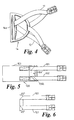
- FIGURE 5 shows schematically a view of an end of a girth strap 100 (the other end is similar) in accordance with the present invention.
- Buckle straps 101 and 102, on main girth strap length 103 are integrally connected together to form a billet strap which can be threaded through fitting/component 104 and folded twice at 45° in order to provide two buckle strap ends extending parallel to one another along the axis of said main girth strap length.
- the billet strap 101,102 is threaded through fitting 104' which is of the same general type as the fitting 104 shown in FIGURE 7.
- the fitting 104' has a wider bridge piece 104'a than the bridge piece 104a shown in FIGURE 7 and it is to be appreciated that the width of this bridge piece can be varied to suit, depending upon the width that the buckle straps 101,102 are to be set apart whilst extending along the main girth length.
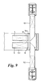
- FIGURE 8 which shows in greater detail one end of the girth strap 103 in which the billet strap 101,102 is attached to the end of the main girth strap length 103 by means of the fitting 104 rather than the fitting 104'.
- the buckle straps 101,102 are shown spaced closer to one another than in the diagrammatic view of FIGURE 5.
- FIGURE 9 shows how the billet strap 101,102 can be threaded through the fitting 104 at right angles to the main girth strap length 103 prior to folding to the position as shown in FIGURE 8.
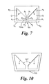
- fitting 104 can be varied to suit and could be modified to the shape of fitting/component 105 shown in FIGURE 10.
- An important feature of the fitting/component 104,104',105 is that the inclined guide edges e of the similar, generally trapezoidal shaped openings O are inclined towards one another generally at 90° and generally at 45° to the axis of the main girth length in order to allow the ends of the buckle straps 101,102 to be folded about the fitting 104,104',105 to extend in a parallel relationship with one another.
- the trapezoidal openings O are mirror images of one another about the axis of the main girth strap length.
- Each opening O has an edge e 1 opposing the guide edge e which aligns with the edge of the billet strap as it is threaded through the openings O and an edge e 2 extending along the axis of the main girth strap.
- the length of edge e 2 is slightly larger than the width of the billet strap.
- the bridge piece 104a is defined by shorter edges e 3 opposed to edges e 2 . It is possible that the openings O could be more triangular with point p 1 being almost coincidental with point p 2 .
- Component/fitting 104 has bar portions b 1 , b 2 defined in part by edges e 1 around which webbing W is looped to attach the component/fitting to the main girth strap length by stitching S.
- the billet strap 101,102 in this way it is an easy matter to replace the billet strap 101,102 with a new one if worn or the billet strap 101,102 can be removed easily for washing or even replaced with a different size (length) of billet strap 101,102 to be used with the same main girth length and thus may easily have the flexibility of use of the same main girth strap length with at least three different sizes of girth strap (to cater for different sizes of animal to which the girth strap is to be attached).
- the billet strap may be of elastic material.
- Two popular girth webbing widths in use are 3",(75mm) and 4",(102mm) and the fitting 104,104',105 can be made of any suitable material for example, metal or plastics.
- the main girth length itself may be suitably shaped or contoured in known manner.
- any range mentioned herein for any variable or parameter shall be taken to include a disclosure of any derivable sub-range within that range or of any particular value of the variable or parameter arranged within, or at an end of, the range or sub-range.
Landscapes
- Engineering & Computer Science (AREA)
- Mechanical Engineering (AREA)
- Buckles (AREA)
Applications Claiming Priority (2)
| Application Number | Priority Date | Filing Date | Title |
|---|---|---|---|
| GB9715612 | 1997-07-25 | ||
| GB9715612A GB2327589A (en) | 1997-07-25 | 1997-07-25 | Girth strap |
Publications (2)
| Publication Number | Publication Date |
|---|---|
| EP0893399A2 true EP0893399A2 (de) | 1999-01-27 |
| EP0893399A3 EP0893399A3 (de) | 1999-12-08 |
Family
ID=10816377
Family Applications (1)
| Application Number | Title | Priority Date | Filing Date |
|---|---|---|---|
| EP98305712A Withdrawn EP0893399A3 (de) | 1997-07-25 | 1998-07-17 | Gurtriemen für Reitsättel |
Country Status (4)
| Country | Link |
|---|---|
| US (1) | US6098383A (de) |
| EP (1) | EP0893399A3 (de) |
| AU (1) | AU7743298A (de) |
| GB (1) | GB2327589A (de) |
Families Citing this family (5)
| Publication number | Priority date | Publication date | Assignee | Title |
|---|---|---|---|---|
| US6363697B1 (en) * | 2000-11-30 | 2002-04-02 | Richard Allen Shapiro | Foal weaning gear |
| ITBS20010058U1 (it) * | 2001-06-20 | 2002-12-20 | Del Garda S R L | Sottopancia per cavalli e altri animali da sella |
| US6695769B2 (en) * | 2001-09-25 | 2004-02-24 | The Foundry, Inc. | Passive ventricular support devices and methods of using them |
| AU2007251894A1 (en) * | 2007-01-09 | 2008-07-24 | Hammersmith Nominees Pty Ltd | Saddle girth |
| GB2585091B (en) * | 2019-06-28 | 2023-02-01 | Jeremy Rudge Saddlery Ltd | A device for securing a saddle to an equine |
Citations (1)
| Publication number | Priority date | Publication date | Assignee | Title |
|---|---|---|---|---|
| GB2166035A (en) | 1984-09-07 | 1986-04-30 | Cottage Ind | Girth or cinch strap |
Family Cites Families (9)
| Publication number | Priority date | Publication date | Assignee | Title |
|---|---|---|---|---|
| US1074498A (en) * | 1911-07-01 | 1913-09-30 | Frisbey G Eiker | Garter. |
| US1252987A (en) * | 1916-12-12 | 1918-01-08 | Eliot Armstrong | Hose-supporter. |
| GB226896A (en) * | 1923-10-08 | 1925-01-08 | William Henry Mclean | Improvements in saddle girths, or surcingles |
| GB282900A (en) * | 1926-10-01 | 1928-01-02 | Harold Edward Sherwin Holt | Improvements in parachute harness |
| US2239764A (en) * | 1938-04-06 | 1941-04-29 | Louis M Vordemberge | Saddle and girth connector |
| US4482319A (en) * | 1983-04-22 | 1984-11-13 | The United States Of America As Represented By The Secretary Of The Navy | Matrix band inset |
| US5355660A (en) * | 1993-10-29 | 1994-10-18 | Shimon Ralph S | Saddle rigging |
| US5433289A (en) * | 1994-07-26 | 1995-07-18 | Surety Manufacturing & Testing Ltd. | Workers' Multi-functional harness |
| DE29613020U1 (de) * | 1996-07-26 | 1996-09-19 | Kavalkade Th. Baggeroer GmbH, 48231 Warendorf | Gurt |
-
1997
- 1997-07-25 GB GB9715612A patent/GB2327589A/en not_active Withdrawn
-
1998
- 1998-07-17 EP EP98305712A patent/EP0893399A3/de not_active Withdrawn
- 1998-07-22 AU AU77432/98A patent/AU7743298A/en not_active Abandoned
- 1998-07-24 US US09/121,839 patent/US6098383A/en not_active Expired - Fee Related
Patent Citations (1)
| Publication number | Priority date | Publication date | Assignee | Title |
|---|---|---|---|---|
| GB2166035A (en) | 1984-09-07 | 1986-04-30 | Cottage Ind | Girth or cinch strap |
Also Published As
| Publication number | Publication date |
|---|---|
| AU7743298A (en) | 1999-02-04 |
| EP0893399A3 (de) | 1999-12-08 |
| GB2327589A (en) | 1999-02-03 |
| GB9715612D0 (en) | 1997-10-01 |
| US6098383A (en) | 2000-08-08 |
Similar Documents
| Publication | Publication Date | Title |
|---|---|---|
| FI86791B (fi) | Saekerhetsdraekt. | |
| US5247905A (en) | Animal harness | |
| US5370083A (en) | Leash-controllable dog harness | |
| CA2162876C (en) | A rucksack harness | |
| US5079904A (en) | Bridle | |
| US4378921A (en) | Negative rotation cinch strap | |
| US6880490B2 (en) | Dog collar having buckle | |
| US4570424A (en) | Cinch for a western saddle | |
| US9655344B1 (en) | Pressure distribution element holding a ring for chest harnesses | |
| US7967109B2 (en) | Belt for roping harness equipped with a salient equipment-carrying device | |
| US6098383A (en) | Equestrian equipment or the like | |
| US2130724A (en) | Derrickman's safety belt | |
| EP2455280B1 (de) | Sicherheitsgurt zum fahren zu zweit auf einem zweirädrigen fahrzeug | |
| GB1560260A (en) | Slings for carrying babies | |
| CA1320052C (en) | Horse bridle | |
| US6237310B1 (en) | Movement-resistant horse rug | |
| US5353577A (en) | Reversible saddle pad | |
| US5048272A (en) | Saddle rigging for use in saddles having rigid trees | |
| US4147015A (en) | Saddle girth | |
| US10757919B2 (en) | Releasable chest pad | |
| US6571541B1 (en) | Billet strap with stretch feature | |
| DE102018124825B4 (de) | Sattelunterlage für ein Pferd | |
| US5355660A (en) | Saddle rigging | |
| DE202011050156U1 (de) | Hundegeschirr, Leine und Halsung | |
| US4813213A (en) | Horse "Z" guide |
Legal Events
| Date | Code | Title | Description |
|---|---|---|---|
| PUAI | Public reference made under article 153(3) epc to a published international application that has entered the european phase |
Free format text: ORIGINAL CODE: 0009012 |
|
| AK | Designated contracting states |
Kind code of ref document: A2 Designated state(s): AT BE CH CY DE DK ES FI FR GB GR IE IT LI LU MC NL PT SE |
|
| AX | Request for extension of the european patent |
Free format text: AL;LT;LV;MK;RO;SI |
|
| PUAL | Search report despatched |
Free format text: ORIGINAL CODE: 0009013 |
|
| AK | Designated contracting states |
Kind code of ref document: A3 Designated state(s): AT BE CH CY DE DK ES FI FR GB GR IE IT LI LU MC NL PT SE |
|
| AX | Request for extension of the european patent |
Free format text: AL;LT;LV;MK;RO;SI |
|
| AKX | Designation fees paid | ||
| REG | Reference to a national code |
Ref country code: DE Ref legal event code: 8566 |
|
| STAA | Information on the status of an ep patent application or granted ep patent |
Free format text: STATUS: THE APPLICATION IS DEEMED TO BE WITHDRAWN |
|
| 18D | Application deemed to be withdrawn |
Effective date: 20000609 |