EP0893401B1 - Verfahren zur Erzeugung von Ozon - Google Patents
Verfahren zur Erzeugung von Ozon Download PDFInfo
- Publication number
- EP0893401B1 EP0893401B1 EP98112593A EP98112593A EP0893401B1 EP 0893401 B1 EP0893401 B1 EP 0893401B1 EP 98112593 A EP98112593 A EP 98112593A EP 98112593 A EP98112593 A EP 98112593A EP 0893401 B1 EP0893401 B1 EP 0893401B1
- Authority
- EP
- European Patent Office
- Prior art keywords
- ozone
- adsorption
- desorption tower
- pressure
- switch valve
- Prior art date
- Legal status (The legal status is an assumption and is not a legal conclusion. Google has not performed a legal analysis and makes no representation as to the accuracy of the status listed.)
- Expired - Lifetime
Links
Images








Classifications
-
- C—CHEMISTRY; METALLURGY
- C01—INORGANIC CHEMISTRY
- C01B—NON-METALLIC ELEMENTS; COMPOUNDS THEREOF; METALLOIDS OR COMPOUNDS THEREOF NOT COVERED BY SUBCLASS C01C
- C01B13/00—Oxygen; Ozone; Oxides or hydroxides in general
- C01B13/10—Preparation of ozone
Definitions
- the present invention relates to a process for producing ozone according to the preamble of claim 1.
- a process for producing ozone is known from the publication "A versatile low-pressure ozone source" published in the document J. Vacuum Sci. Techn. 9 (4) 1991, pages 2408 and 2409.
- ozone water of high density In order to produce high density ozone water, it is more advantageous to employ a so-called intermittent ozone producing method, wherein a small sized ozone generator of small capacity is used to store the produced ozone by using an adsorbent over a long period and to take this stored ozone out from the adsorbent when required for producing high density ozone water, than producing ozone with an ozone generator of large capacity, in view of initial and running costs.
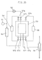
- An ozone producing apparatus employing such an ozone producing method is known to comprise the following components as shown in Fig. 25: an ozone generator 50, an oxygen supply source 51, a circulating blower 52, an adsorption/desorption tower 53, a cooling source 54, a heating source 55, a water flow ejector 56 and switch valves 57a to 57g.
- the adsorption/desorption tower 53 is of double cylinder type of which inner cylinder is filled with an ozone adsorbent and an outer cylinder with heating medium. Silica gel might be employed as the ozone adsorbent, and ethylene glycol or alcohol group as the heating medium.
- the circulating blower 52, ozone generator 50 and adsorption/desorption tower 53 constitute, in this order, a circulating system.
- Oxygen is supplied by the oxygen supply source 51 so that the pressure in the circulating system OL is always constant. In this case, the pressure is normally maintained at 1.5 kg/cm 2 .
- oxygen is made to flow in the circulating system by the circulating blower 52 while the switch valves 57c and 57d are in an opened condition, a part of the oxygen is converted into ozone to generate an ozonized oxygen while passing through the discharge space of the ozone generator 50, and the ozonized oxygen is then transferred to the adsorption/desorption tower 53.
- the adsorbent in the adsorption/desorption tower 53 selectively adsorbs ozone, and the remaining oxygen is returned to the circulating blower 52 through the switch valve 57c. Oxygen which has been consumed as ozone to be adsorbed is supplemented through the oxygen supply source 51. Since the adsorbent assumes a property that adsorption capacity of ozone varies depending on temperature, the adsorbent is cooled by the cooling source 54 to not more than -30°C. That is, the lower the temperature becomes, an amount of ozone adsorption increases, while the higher the temperature becomes, it decreases. Accordingly, the temperature of adsorbent is raised by the heating source 55 when desorbing ozone.
- the desorbing operation of ozone is performed.
- operations of the ozone generator 50, circulating blower 52 and cooling source 54 are terminated and the switch valves 57a to 57d are closed.
- the heating source 55 and water flow ejector 56 start their operation and switch valves 57e to 57g are opened.
- temperature of the adsorbent is raised by applying heat through the heating source 55 so that ozone which has been adsorbed by the adsorbent can be easily desorbed therefrom.
- the cooling source 54 is terminated whereupon the temperature of the ozone adsorbent in the adsorption/desorption tower 53 rises to cause a decrease in the amount of adsorbed ozone. Consequently, there is caused a drawback that ozone which has been adsorbed by the adsorbent separates therefrom and ozone filling the adsorption/desorption tower 53 at a high density and a high pressure rapidly starts decomposition whereby stored ozone is consumed wastefully. Also in case of power failure during a desorbing process, ozone filling the adsorption/desorption tower 53 at a high density and a high pressure can not be taken out therefrom.
- the document US-A-4 453 953 discloses an intermittent ozone feeding apparatus where a connection is provided between the adsorption/desorption tower and the water ejector in a water supply conduit. A similar structure is used in connection with the apparatus of the present application as described below. However, the document US-A-4 453 953 does not deal with any safety devices or means for handling a power failure and/or a situation when the apparatus is under an abnormal driving condition, for example when the pressure range and/or the temperature range has deviated from a predetermined range.
- the document JP-A-09-142 808 discloses a method intended for controlling an ozonizer capable of significantly shortening or obviating purge time, reducing oxygen consumption and stably feeding ozone gas at a specified concentration and flow rate.
- the conventional ozonizer has an ozone generator to produce ozone from oxygen, ozone adsorption equipment to adsorb the ozone to an adsorbent and an ozone discharge line to discharge, together with a carrier gas, the ozone desorbed by feeding the ozone adsorption equipment with the carrier gas.
- the ozone is desorbed in the ozone adsorption equipment, and the ozone thus desorbed is stored, together with the carrier gas, in an ozone tank which is then fed with a diluting gas to control the ozone at a desired concentration.
- the necessary amount of ozone is calculated based on a desired ozone concentration and flow rate, wherein temperature and pressure in the ozone adsorption equipment are controlled so as to desorb the amount of ozone.
- the document US-A-5 520 887 also deals with an apparatus for generating and condensing ozone.
- the ozone is used together with nitrogen as a carrier gas in a reaction tower for treating materials.
- the supply of ozone and mixing with nitrogen prior to the supply of the gas mixture the reaction tower is described in detail.
- no emergency device or safety device is disclosed which deals with a situation of a power failure or any abnormal driving condition with excessive temperature and/or pressure.
- the object underlying the present invention is to provide a process for producing ozone wherein in a corresponding apparatus for producing the ozone a destruction of the apparatus, explosion or fire can be prevented and wherein the adsorbed ozone can safely be treated even if a situation arises where electrical power fails or where the apparatus is under an abnormal driving condition such that a high pressure and/or a high temperature condition arises in the adsorption/desorption tower.
- the ozone producing apparatus for a process according to the present invention is arranged to perform the following operations upon detection of power failure and/or an abnormal driving condition in which pressure or temperature in the adsorption/desorption tower has deviated from a predetermined range: (1) introducing desorbed ozone of high density to the reducer storage for making ozone react with the reducer; (2) introducing desorbed ozone of high density to the silica gel filler for equalizing the ozone density and for decomposing by means of the ozone decomposer; (3) providing a piping for supplying ozone directly to places where ozone is used and for introducing desorbed ozone of high density, (4) introducing desorbed ozone of high density to the gas storage for equalizing the ozone density and for decomposing by means of the ozone decomposer; and (5) automatically returning to the original driving condition when the apparatus has restored from an abnormal driving condition to a normal condition.
- adsorbed and stored ozone is prevented from being rapidly decomposed and adsorbed ozone can be safely treated even in case of power failure or an abnormal driving condition in which high pressure or high temperature exists in the adsorption/desorption tower, and after restoring to the normal condition from the abnormal driving condition, the apparatus returns its original driving condition automatically so that ozone can be safely produced.
- Fig. 1 is a diagram showing an arrangement of an ozone producing apparatus for a process according to Embodiment 1 of the present invention.
- the apparatus comprises an ozone generator 1, an oxygen supply source 2, a circulating blower 3, an adsorption/desorption tower 4, a cooling source 5, a heating source 6, a water flow ejector 7 which serves as an ozone desorbing means, switch valve 8a to 8g, 9, and a reducer storage 10.
- the switch valve 9 and reducer storage 10 are connected to the adsorption/desorption tower 4 by a piping La.
- a reducer such as sodium thiosulfate solution or potassium iodide is stored. It should be noted that the switch valve 9 is made to be driven by an emergency power supply.
- ozone which is stored in the adsorption/desorption tower 4 is introduced to the reducer storage for decomposing in case of abnormal driving condition, adsorbed and stored ozone can be prevented from being rapidly decomposed, and adsorbed ozone can be safely treated. Further, by using a reducer, it is enabled not only to safely treat even ozone of high density but also to reduce capacity of the apparatus for realizing downsizing thereof.
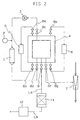
- Fig. 2 is a diagram showing an arrangement of an ozone producing apparatus for a process according to Embodiment 2 of the present invention.
- numeral 11 denotes a filler, 12 an ozone decomposer, and the interior of the filler 11 is filled with porous material impregnated, for instance, with silica gel, activated alumina or fluorocarbon.
- the filler 11 and switch valve 9 are connected to the adsorption/desorption tower 4 via a first piping La.
- the filler 11 and the ozone decomposer 12 are connected to each other via a second piping Lb.
- ozone decomposer 12 is filled with an ozone decomposing catalyst which might be of activated carbon or of manganese type, but the present invention is not limited thereto, and the ozone decomposer might also be an ozone decomposer employing a thermal cracking method.
- ozone decomposer 12 is filled with an ozone decomposing catalyst which might be of activated carbon or of manganese type, but the present invention is not limited thereto, and the ozone decomposer might also be an ozone decomposer employing a thermal cracking method.
- the remaining arrangements are equal to those of Fig. 1.
- ozone-containing gas of decreased density and pressure When the ozone-containing gas of decreased density and pressure is supplied to the filler 11, a part of ozone of high density is adsorbed while passing through the silica gel filler layer since silica gel has a property to selectively adsorb ozone. In this way, ozone-containing gas of decreased ozone density is sent to the ozone decomposer 12 via the piping Lb and ozone is decomposed thereafter.
- the ozone decomposer 12 Since ozone which is stored in the adsorption/desorption tower 4 is introduced through the filler 11 to the ozone decomposer 12 after equalizing the ozone density for decomposition in case of abnormal driving condition, the ozone decomposer 12 might be of small size since it is not necessary to manufacture the ozone decomposer to be suitable for ozone of high pressure and high density at the initial stage of exhaustion. Further, since ozone which is stored in the adsorption/desorption tower 4 is exhausted and decomposed by opening the switch valve 9 in case of an abnormal driving condition, adsorbed and stored ozone is prevented from being rapidly decomposed and adsorbed ozone can be safely treated.
- Fig. 3 is a diagram showing an arrangement of an ozone producing apparatus for a process according to Embodiment 3 of the present invention.
- the piping La is connected to the switch valve 9 and to a water piping Lc on the downstream side of the water flow ejector 7.
- the water flow ejector 7 is connected to a branching piping Ld of the water piping Lc, and ozone is designed to be injected into water sent from a pump P operated by an emergency power supply.
- the remaining arrangements are identical with those of Fig. 1.
- ozone stored in the adsorption/desorption tower 4 is introduced and injected into the water piping Lc of the water flow ejector 7 in order to make ozone react with reactive substances in the water such as organic substances for treatment in case of an abnormal driving condition, ozone which is adsorbed and stored is prevented from being rapidly decomposed and adsorbed ozone can be safely treated even under an abnormal driving condition. Further, since it is sufficient to provide a switch valve and piping in this method, the apparatus can be simplified.
- Fig. 4 is a diagram showing an arrangement of an ozone producing apparatus for a process according to Embodiment 4 of the present invention.
- numeral 13 denotes a gas storage which is connected to the switch valve 9 via the piping La.
- the remaining arrangements are identical with those of Fig. 1.
- the ozone-containing gas stored in the gas storage 13 is again supplied to the water flow ejector 7 through the piping La, adsorption/desorption tower 4 and piping Ld, and is dispersed and dissolved into water in the water flow ejector 7.
- ozone which is stored in the adsorption/desorption tower 4 is temporarily stored in the gas storage 13 in case of an abnormal driving condition, ozone which is adsorbed and stored is prevented from being rapidly decomposed and adsorbed ozone can be made good use of even under an abnormal driving condition. Further, since it is sufficient to provide a switch valve, piping and a gas storage in this embodiment, the apparatus can be simplified.
- Fig. 5 is a diagram showing an arrangement of an ozone producing apparatus for a process according to Embodiment 5 of the present invention.
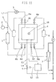
- the apparatus comprises a monitor 14 for monitoring electricity supply conditions to the apparatus, which is an electricity supply monitoring means, a control circuit 15, and signal lines S1, S2.
- the remaining arrangements are identical with those of Fig. 1.
- An output signal from the electricity supply condition monitor 14 is connected to an input of the control circuit 15 via the signal line 51, and an output of the control circuit 15 is connected to the switch valve 9 via the signal line S2 as an opening/closing signal for the switch valve 9.
- the electricity supply condition to the apparatus during driving is continuously observed by the electricity supply condition monitor 14, and when power failure is detected, a corresponding signal is transmitted to the control circuit 15 via the signal line S1.
- the control circuit 15 sends immediately, or depending, the driving condition, an opening/closing or opening degree adjusting signal for the switch valve 9 to the switch valve 9 via the signal line S2, and based on this signal the opened/closed condition or the opening degree is controlled at the switch valve 9.
- this apparatus is an apparatus for producing ozone by repeating an ozone adsorbing and storing process and a desorbing process, and it is possible to change timings for sending an opening/closing or opening degree control signal for the switch valve 9 between the ozone adsorbing and storing process, and the desorbing process.
- the switch valve 9 is preferably operated immediately, since ozone of high density remains in the adsorption/desorption tower 4 at a high pressure.
- the adsorption/desorption tower 4 is at a negative pressure, so that the switch valve 8f is preferably closed immediately and the switch valve 9 might be operated after a specified time has lapsed, and the ozone pressure and density in the adsorption/desorption tower 4 has raised.
- the switch valve 9 might be operated after a specified time has lapsed and when temperature in the adsorption/desorption tower 4 starts rising, since the adsorption/desorption tower 4 is maintained at a low temperature by the cooling source 5 and the temperature of the adsorbent does not rise immediately after power failure.
- Monitoring of electricity supply condition to the apparatus might be performed, for instance, by utilizing a contact signal of a relay provided in the electricity supply line, and monitoring of a lapsed time after power failure might be performed by providing a timer in the control circuit 15. Further, supply of power at the time of power failure might be performed by using, for instance, a storage battery. Each of these measures can be performed easily and at low cost.
- Fig. 6 is a diagram showing an arrangement of an ozone producing apparatus for a process according to Embodiment 6 of the present invention.
- the apparatus of this embodiment is arranged in such a manner that the reducer storage 10 of Embodiment 5 has been replaced by the filler 11 and the ozone decomposer 12 of Embodiment 2.
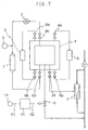
- Fig. 7 is a diagram showing an arrangement of an ozone producing apparatus for a process according to Embodiment 7 of the present invention.
- the apparatus of this embodiment is arranged in such a manner that the monitoring means of Embodiments 5 and 6 is connected to the piping La of Embodiment 3.
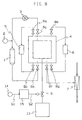
- Fig. 8 is a diagram showing an arrangement of an ozone producing apparatus for a process according to Embodiment 8 of the present invention.
- the apparatus of this embodiment is arranged in such a manner that the monitoring means of Embodiments 5 to 7 is connected to the piping La of Embodiment 4.
- Fig. 9 is a diagram showing an arrangement of an ozone producing apparatus for a process according to Embodiment 9 of the present invention.
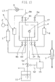
- the apparatus of Fig. 9 includes a pressure detecting means, and numeral 16 denotes a pressure gauge for measuring an internal pressure in the adsorption/desorption tower 4, and S3 a signal line.
- An output signal of the pressure gauge 16 is connected to an input of the control circuit 15 via the signal line S3, and an output of the control circuit 15 is connected to the switch valve 9 via the signal line S2 as an opening/closing signal for the switch valve 9.
- the remaining arrangements are identical with those of Fig. 1 and Fig. 5.
- the internal pressure of the adsorption/desorption tower 4 is continuously monitored by the pressure gauge 16, and a corresponding signal is transferred to the control circuit 15 via the signal line S3.
- the control circuit 15 sends an opening/closing or opening degree adjusting signal for the switch valve 9 to the switch valve 9 via the signal line S2 when the obtained valve of the pressure gauge 16 is deviated from a predetermined suitable pressure range for each driving process.
- the switch valve 9 is then controlled based on this signal to change its opened/closed condition or its opening degree.
- a predetermined suitable pressure range for each driving process indicates the following : this apparatus is an apparatus for producing ozone by repeating an ozone adsorbing and storing process and an ozone desorbing process, and conditions for the driving pressure are different between the ozone adsorbing and storing process, and the desorbing process. That is, adsorption is normally performed in the presence of pressure and desorption in the presence of negative pressure. Therefore, a more delicate measure for coping with abnormal driving conditions might be performed by setting different pressure ranges between the ozone adsorbing and storing process, and the desorbing process.
- the suitable pressure ranges for each of the driving processes can be preliminarily set based on experiments, pressure resistivity of the adsorption/desorption tower 4, driving pressure of the ozone generator (set pressure for the piping L1 during adsorbing and storing process), or vacuum reaching pressure of the ejector 7.
- the driving pressure for the ozone generator or, when a pressure rising blower is provided (though not shown in the drawings) a driving discharge power thereof is made to be the suitable driving condition
- the vacuum pressure reaching pressure of the ejector or, when of performing gas purge (though not shown in the drawings), the pressure of supplied gas is made to be the suitable driving condition.
- a range of suitable driving conditions might be set by adding upper and lower surpluses to these driving conditions, they might be set, in view of the performance, utility or costs for each of the present devices, in a range of 0 to 20 kg/cm 2 G, and preferably 0 to 12 kg/cm 2 G for the adsorbing process, and in a range of 0 to 1 kg/cm 2 ABS, and preferably 0.01 to 0.5 kg/cm 2 ABS for the desorbing process.
- the pressure in the adsorption/desorption tower 4 is automatically measured and the opening/closing condition or the opening degree of the switch valve 9 is controlled based on the obtained pressure signal and a predetermined suitable pressure range for the driving process in order to draw ozone stored in the adsorption/desorption tower 4 even in the case where the pressure in the adsorption/desorption tower 4 is deviated from a suitable range for the driving condition and the apparatus is under an abnormal driving condition.
- adsorbed and stored ozone is prevented from being rapidly decomposed even under an abnormal driving condition, and safe driving can be performed.
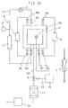
- Fig. 10 is a diagram showing an arrangement of an ozone producing apparatus for a process according to Embodiment 10 of the present invention.
- the apparatus of this embodiment is arranged in such a manner that the reducer storage 10 of Embodiment 9 is replaced by the silica gel filler 11 and ozone decomposer 12 of Embodiment 2.
- Operations of the apparatus of Fig. 10 are almost identical with those of the apparatus of Fig. 9. That is, the internal pressure in the adsorption/desorption tower 4 is continuously monitored by the pressure gauge 16, and the obtained value is supplied to the control circuit 15 via the signal line S3.
- the control circuit 15 compares the internal pressure in the adsorption/desorption tower 4 obtained as a measured value of the pressure gauge 16 and a suitable pressure range which is preliminarily set for each of the ozone adsorbing process and ozone desorbing process.
- a suitable pressure range which is preliminarily set for each of the ozone adsorbing process and ozone desorbing process.
- an opening/closing condition or opening degree adjusting signal for the switch valve 9 is sent to the switch valve 9 via the signal line S2. Based upon this signal, the opening/closing condition or opening degree is controlled at the switch valve 9.
- the suitable pressure ranges for each of the driving processes can be preliminarily set based on experiments, pressure resistivity of the adsorption/desorption tower 4, driving pressure of the ozone generator (set pressure for the piping L1 during adsorbing and storing process), or vacuum reaching pressure of the ejector 7, similarly to the apparatus of Fig. 9.
- the pressure in the adsorption/desorption tower 4 is automatically measured and the opening/closing condition or the opening degree of the switch valve 9 is controlled based on the obtained pressure signal and a predetermined suitable pressure range for the driving process in order to draw ozone stored in the adsorption/desorption tower 4 even in the case where the pressure in the adsorption/desorption tower 4 is deviated from a suitable range for the driving condition and the apparatus is under an abnormal driving condition.
- adsorbed and stored ozone is prevented from being rapidly decomposed even under an abnormal driving condition, and safe driving can be performed.
- Fig. 11 is a diagram showing an arrangement of an ozone producing apparatus for a process according to Embodiment 11 of the present invention.
- the apparatus of this embodiment is arranged in such a manner that the pressure detecting means of Embodiment 9 and 10 is connected to the piping La of Embodiment 3.
- Operations of the apparatus of Fig. 11 are almost identical with those of the apparatus of Fig. 10 and the apparatus of Fig. 9, wherein the internal pressure in the adsorption/desorption tower 4 during driving is continuously monitored by the pressure gauge, and the obtained value is supplied to the control circuit 15 via the signal line S3.
- the control circuit 15 compares the internal pressure in the adsorption/desorption tower 4 obtained as a measured value of the pressure gauge 16 and a predetermined suitable pressure range for each of the ozone adsorbing process and ozone desorbing process.
- a predetermined suitable pressure range for each of the ozone adsorbing process and ozone desorbing process is sent to the switch valve 9 via the signal line S2. Based upon this signal, the opening/closing condition or opening degree is controlled at the switch valve 9.
- the suitable pressure ranges for each of the driving processes can be preliminarily set based on experiments, pressure resistivity of the adsorption/desorption tower 4, driving pressure of the ozone generator (set pressure for the piping L1 during adsorbing and storing process), or vacuum reaching pressure of the ejector 7, similarly to the apparatuses of Figs. 9 and 10.
- the pressure in the adsorption/desorption tower 4 is automatically measured and the opening/closing condition or the opening degree of the switch valve 9 is controlled based on the obtained pressure signal and a predetermined suitable pressure range for the driving process in order to draw ozone stored in the adsorption/desorption tower 4 even in the case where the pressure in the adsorption/desorption tower 4 is deviated from a suitable range for the driving condition and the apparatus is under an abnormal driving condition.
- adsorbed and stored ozone is prevented from being rapidly decomposed even under an abnormal driving condition, and safe driving can be performed.
- Fig. 12 is a diagrams showing an arrangement of an ozone producing apparatus for a process according to Embodiment 12 of the present invention.
- the apparatus of this embodiment is arranged in such a manner that the pressure detecting means of Embodiments 9 to 11 is connected to the piping La of Embodiment 4.
- Operations of the apparatus of Fig. 12 are almost identical with those of the apparatuses of Figs. 9 to 11, wherein the internal pressure in the adsorption/desorption tower 4 during driving is continuously monitored by the pressure gauge 16, and the obtained value is supplied to the control circuit 15 via the signal line S3.
- the control circuit 15 compares the internal pressure in the adsorption/desorption tower 4 obtained as a measured value of the pressure gauge 16 and a predetermined suitable pressure range for each of the ozone adsorbing process and ozone desorbing process.
- a predetermined suitable pressure range for each of the ozone adsorbing process and ozone desorbing process is sent to the switch valve 9 via the signal line S2. Based upon this signal, the opening/closing condition or opening degree is controlled at the switch valve 9.
- the suitable pressure ranges for each of the driving processes can be preliminarily set based on experiments, pressure resistivity of the adsorption/desorption tower 4, driving pressure of the ozone generator (set pressure for the piping L1 during adsorbing and storing process), or vacuum reaching pressure of the ejector 7, similarly to the apparatuses of Figs. 9 and 10.
- the pressure in the adsorption/desorption tower 4 is automatically measured and the opening/closing condition or the opening degree of the switch valve 9 is controlled based on the obtained pressure signal and a predetermined suitable pressure range for the driving process in order to draw ozone stored in the adsorption/desorption tower 4 for storing in the gas storage 13 even in the case where the pressure in the adsorption/desorption tower 4 is deviated from a suitable range for the driving condition, and the apparatus is under an abnormal driving condition.
- explosion, fire or destruction of the apparatus can be prevented and adsorbed ozone can be made good use even in the case where the pressure is deviated from a suitable range.
- Fig. 13 is a diagram showing an arrangement of an ozone producing apparatus for a process according to Embodiment 13 of the present invention.
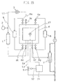
- the apparatus includes a temperature detecting means, and numeral 17 denotes a thermometer for measuring an internal temperature of the adsorption/desorption tower 4, and S4 a signal line.
- An output signal of the thermometer 17 is connected to an input of the control circuit 15 via the signal line S4, and an output of the control circuit 15 is connected to the switch valve 9 via the signal line S2 as an opening/closing signal for the switch valve 9.
- the remaining arrangements are identical with those of the apparatuses of Figs. 1, 5 and 9.
- the internal temperature of the adsorption/desorption tower 4 is continuously monitored by the thermometer 17, and a corresponding signal is transferred to the control circuit 15 via the signal line S4.
- the control circuit 15 sends an opening/closing or opening degree adjusting signal for the switch valve 9 to the switch valve 9 via the signal line S2 when the obtained valve of the thermometer 17 is deviated from a predetermined suitable temperature range for each driving process, and the switch valve 9 is then controlled based on this signal to change its opened/closed condition or its opening degree.
- the suitable temperature ranges for each of the driving processes can be preliminarily set based on experiments, set temperature for the cooling source 5, set temperature the heating source 6, or an adsorption/desorption quantity of ozone with respect to silica gel or the like.
- a predetermined suitable temperature range for each driving process indicates the following: this apparatus is an apparatus for producing ozone by repeating an ozone adsorbing and storing process and an ozone desorbing process, and the driving temperatures differ between the adsorbing process and the desorbing process.
- the adsorbing process is generally performed at a low temperature and the desorbing process generally at a room temperature.
- a practical temperature range might be set in a range of 30°C to -100°C in the adsorbing process and 80°C to -100°C in the desorbing process.
- the temperature in the adsorption/desorption tower 4 is automatically measured and the opening/closing condition or the opening degree of the switch valve 9 is controlled based on the obtained temperature signal and a predetermined suitable temperature range for the driving process in order to draw ozone stored in the adsorption/desorption tower 4 even in the case where the temperature in the adsorption/desorption tower 4 is deviated from a suitable range for the driving condition and the apparatus is under an abnormal driving condition.
- adsorbed and stored ozone is prevented from being rapidly decomposed even under an abnormal driving condition, and safe driving can be performed.
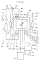
- Fig. 14 is a diagram showing an arrangement of an ozone producing apparatus for a process according to Embodiment 14 of the present invention.
- the apparatus of this embodiment is arranged in such a manner that the reducer storage 10 of Embodiment 13 is replaced by the silica gel filler 11 and ozone decomposer 12 of Embodiment 2.
- Operations of the apparatus of Fig. 14 are almost identical with those of the apparatus of Fig. 13. That is, the internal temperature in the adsorption/desorption tower 4 is continuously monitored by the thermometer 17, and the obtained value is supplied to the control circuit 15 via the signal line S4.
- the control circuit 15 compares the internal temperature in the adsorption/desorption tower 4 obtained as a measured value of the thermometer 17 and a predetermined suitable temperature range for each of the ozone adsorbing process and ozone desorbing process.
- a predetermined suitable temperature range for each of the ozone adsorbing process and ozone desorbing process is sent to the switch valve 9 via the signal line S2. Based upon this signal, the opening/closing condition or opening degree is controlled at the switch valve 9.
- the suitable temperature ranges for each of the driving processes can be preliminarily set based on experiments, set temperature for the cooling source 5, set temperature for the heating source 6, or an adsorption/desorption heat quantity of ozone with respect to silica gel or the like, similarly to the apparatus of Embodiment 13.
- the temperature in the adsorption/desorption tower 4 is automatically measured and the opening/closing condition or the opening degree of the switch valve 9 is controlled based on the obtained temperature signal and a predetermined suitable temperature range for the driving process in order to draw ozone stored in the adsorption/desorption tower 4 even in the case where the temperature in the adsorption/desorption tower 4 is deviated from a suitable range for the driving condition and the apparatus is under an abnormal driving condition.
- adsorbed and stored ozone is prevented from being rapidly decomposed even under an abnormal driving condition, and safe driving can be performed.
- Fig. 15 is a diagram showing an arrangement of an ozone producing apparatus for a process according to Embodiment 15 of the present invention.
- the apparatus of this embodiment is arranged in such a manner that the temperature detecting means of Embodiments 13 and 14 is connected to the piping La of Embodiment 3.
- Operations of the apparatus of Fig. 15 are almost identical with those of the apparatus of Fig. 14 and the apparatus of Fig. 13. That is, the internal temperature in the adsorption/desorption tower 4 is continuously monitored by the thermometer 17, and the obtained value is supplied to the control circuit 15 via the signal line S4.
- the control circuit 15 compares the internal temperature in the adsorption/desorption tower 4 obtained by the thermometer 17 and a predetermined suitable temperature for each of the ozone adsorbing process and ozone desorbing process. When the measured value of the thermometer 17 is deviated from this range, a signal is sent to the switch valve 9 and based on this signal the switch valve 9 controls the opening/closing condition or opening degree.
- the suitable temperature ranges for each of the driving processes can be preliminarily set based on experiments, set temperature for the cooling source 5, set temperature for the heating source 6, or an adsorption/desorption heat quantity of ozone with respect to silica gel or the like, similarly to the apparatuses of Embodiments 13 and 14.
- the temperature in the adsorption/desorption tower 4 is automatically measured and the opening/closing condition or the opening degree of the switch valve 9 is controlled based on the obtained temperature signal and a predetermined suitable temperature range for the driving process in order to draw ozone stored in the adsorption/desorption tower 4 even in the case where the temperature in the adsorption/desorption tower 4 is deviated from a suitable range for the driving condition and the apparatus is under an abnormal driving condition.
- adsorbed and stored ozone is prevented from being rapidly decomposed even under an abnormal driving condition, and safe driving can be performed.
- Fig. 16 is a diagram showing an arrangement of an ozone producing apparatus for a process according to Embodiment 16 of the present invention.
- the apparatus of this embodiment is arranged in such a manner that the temperature detecting means of Embodiments 13 to 15 is connected to the piping La of Embodiment 4.
- Operations of the apparatus of Fig. 16 are almost identical with those of the apparatuses of Figs. 13 to 15. That is, the internal temperature in the adsorption/desorption tower 4 is continuously monitored by the thermometer 17, and the obtained value is supplied to the control circuit 15 via the signal line S4.
- the control circuit 15 compares the internal temperature in the adsorption/desorption tower 4 obtained by the thermometer 17 and a predetermined suitable temperature range for each of the ozone adsorbing process and ozone desorbing process. When the measured value of the thermometer 17 is deviated from this range, a signal is sent to the switch valve 9 and based on this signal the switch valve 9 controls the opening/closing condition or opening degree.
- the suitable temperature ranges for each of the driving processes can be preliminarily set based on experiments, set temperature for the cooling source 5, set temperature for the heating source 6, or an adsorption/desorption heat quantity of ozone with respect to silica gel or the like, similarly to the apparatuses of Embodiments 13 and 14.
- the temperature in the adsorption/desorption tower 4 is automatically measured and the opening/closing condition or the opening degree of the switch valve 9 is controlled based on the obtained temperature signal and a predetermined suitable temperature range for the driving process in order to draw ozone stored in the adsorption/desorption tower 4 for storing in the gas storage 13 even in the case where the temperature in the adsorption/desorption tower 4 is deviated from a suitable range for the driving condition and the apparatus is under an abnormal driving condition.
- adsorbed and stored ozone is prevented from being rapidly decomposed, safe driving can be performed, and adsorbed ozone can be made good use of even under an abnormal driving condition.
- Fig. 17 is a diagram showing an arrangement of an ozone producing apparatus for a process according to Embodiment 17 of the present invention.
- the apparatus of this embodiment is arranged in such a manner that the pressure detecting means of Embodiment 9 and the temperature detecting means of Embodiment 13 are connected to the monitoring means of Embodiment 5.
- the remaining arrangements are identical with those of the apparatuses of Figs. 1, 5, 9, and 13.
- an output signal of the electricity supply condition monitor 14, a measuring signal of the pressure gauge 16 and a signal of the thermometer 17 are simultaneously output to the control circuit 15 via the signal lines S1, S3 and S4, respectively.
- an opening/closing or opening degree adjusting signal for the switch valve 9 is sent to the switch valve 9 via the signal line S2 when either of these values has deviated from a predetermined suitable driving condition range, and based on this signal the opening/closing condition or opening degree is controlled at the switch valve 9.
- Monitoring of electricity supply condition to the apparatus might be performed, for instance, by utilizing a contact signal of a relay provided in the electricity supply line, and monitoring of a lapsed time after power failure might be performed by providing a timer in the control circuit 15. Further, supply of power at the time of power failure might be performed by using, for instance, a storage battery. Each of these measures can be performed easily and at low cost.
- the suitable pressure and temperature ranges for each of the driving processes can be preliminarily set based on experiments, pressure resistivity of the adsorption/desorption tower 4, driving pressure of the ozone generator (set pressure for the piping L1 during adsorbing and storing process), vacuum reaching pressure of the ejector 7, set temperature for the cooling source 5, set temperature for the heating source 6, or an adsorption/desorption heat quantity of ozone with respect to silica gel or the like.
- the electricity supply condition to the apparatus, and pressure and temperature in the adsorption/desorption tower 4 are automatically measured, and the opening/closing condition or the opening degree of the switch valve 9 is controlled based on these measured signals and preliminarily set suitable driving condition ranges for the driving process in order to draw ozone stored in the adsorption/desorption tower 4 even in the case where electricity supply to the apparatus is terminated or where the pressure or temperature in the adsorption/desorption tower 4 is deviated from a suitable ranged for the driving condition and the apparatus is under an abnormal driving condition.
- adsorbed and stored ozone is prevented from being rapidly decomposed even under an abnormal driving condition, and safe driving can be performed. It should be noted that by simultaneously monitoring electricity supply condition to the apparatus, and pressure and temperature in the adsorption/desorption tower 4 as in the apparatus of Fig. 17, abnormalities in the driving condition can be more accurately determined than in apparatuses of Embodiments 1 to 16.
- Fig. 18 is a diagram showing an arrangement of an ozone producing apparatus for a process according to Embodiment 18 of the present invention.
- the apparatus of this embodiment is arranged in such a manner that the reducer storage 10 of Embodiment 17 is replaced by the filler 11 and ozone decomposer 12 of Embodiment 2.
- Monitoring of electricity supply condition to the apparatus might be performed, similarly to the apparatus of Fig. 17, by utilizing a contact signal of a relay provided in the electricity supply line, and monitoring of a lapsed time after power failure might be performed by providing a timer in the control circuit 15. Further, supply of power at the time of power failure might be performed by using, for instance, a storage battery. Each of these measures can be performed easily and at low cost.
- the suitable pressure and temperature ranges for each of the driving processes can be preliminarily set based on experiments, pressure resistivity of the adsorption/desorption tower 4, driving pressure of the ozone generator (set pressure for the piping L1 during adsorbing and storing process), vacuum reaching pressure of the ejector 7, set temperature for the cooling source 5, set temperature for the heating source 6, or an adsorption/desorption heat quantity of ozone with respect to silica gel or the like.
- the electricity supply condition to the apparatus, and pressure and temperature in the adsorption/desorption tower 4 are automatically measured, and the opening/closing condition or the opening degree of the switch valve 9 is controlled based on these measured signals and preliminarily set suitable driving condition ranges for the driving process in order to draw ozone stored in the adsorption/desorption tower 4 even in the case where electricity supply to the apparatus is terminated or where the pressure or temperature in the adsorption/desorption tower 4 is deviated from a suitable range for the driving condition and the apparatus is under an abnormal driving condition.
- adsorbed and stored ozone can be prevented from being rapidly decomposed even under an abnormal driving condition, and safe driving can be performed.
- Fig. 19 is a diagram showing an arrangement of an ozone producing apparatus for a process according to Embodiment 19 of the present invention.
- the apparatus of this embodiment is arranged in such a manner that the pressure detecting means of Embodiment 9 and the temperature detecting means of Embodiment 13 are connected to the monitoring means of Embodiment 7.
- an opening/closing or opening degree adjusting signal for the switch valve 9 is sent to the switch valve via the signal line S2 when either of these values has deviated from a predetermined suitable driving condition range, and based on this signal the opening/closing condition or opening degree is controlled at the switch valve 9.
- Monitoring of electricity supply condition to the apparatus might be performed, similarly to the apparatuses of Figs. 17 and 18, by utilizing a contact signal of a relay provided in the electricity supply line, and monitoring of a lapsed time after power failure might be performed by providing a timer in the control circuit 15. Further, supply of power at the time of power failure might be performed by using, for instance, a storage battery. Each of these measures can be performed easily and at low cost.
- the suitable pressure and temperature ranges for each of the driving processes can be preliminarily set based on experiments, pressure resistivity of the adsorption/desorption tower 4, driving pressure of the ozone generator (set pressure for the piping L1 during adsorbing and storing process), vacuum reaching pressure of the ejector 7, set temperature for the cooling source 5, set temperature for the heating source 6, or an adsorption/desorption heat quantity of ozone with respect to silica gel or the like
- the electricity supply condition to the apparatus, and pressure and temperature in the adsorption/desorption tower 4 are automatically measured, and the opening/closing condition or the opening degree of the switch valve 9 is controlled based on these measured signals and preliminarily set suitable driving condition ranges for the driving process in order to draw ozone stored in the adsorption/desorption tower 4 even in the case where electricity supply to the apparatus is terminated or where the pressure or temperature in the adsorption/desorption tower 4 is deviated from a suitable range for the driving condition and the apparatus is under an abnormal driving condition.
- adsorbed and stored ozone can be prevented from being rapidly decomposed even under an abnormal driving condition, and safe driving can be performed.
- Fig. 20 is a diagram showing an arrangement of an ozone producing apparatus for a process according to Embodiment 20 of the present invention.
- the apparatus of this embodiment is arranged in such a manner that the pressure detecting means of Embodiment 9 and the temperature detecting means of Embodiment 13 are connected to the monitoring means of Embodiment 8.
- an opening/closing or opening degree adjusting signal for the switch valve 9 is sent to the switch valve via the signal line S2 when either of these values has deviated from a predetermined suitable driving condition range, and based on this signal the opening/closing condition or opening degree is controlled at the switch valve 9.
- Monitoring of electricity supply condition to the apparatus might be performed, similarly to the apparatuses of Embodiments 17 to 19, by utilizing a contact signal of a relay provided in the electricity supply line, and monitoring of a lapsed time after power failure might be performed by providing a timer in the control circuit 15. Further, supply of power at the time of power failure might be performed by using, for instance, a storage battery. Each of these measures can be performed easily and at low cost.
- the suitable pressure and temperature ranges for each of the driving processes can be preliminarily set based on experiments, pressure resistivity of the adsorption/desorption tower 4, driving pressure of the ozone generator (set pressure for the piping L1 during adsorbing and storing process), vacuum reaching pressure of the ejector 7, set temperature for the cooling source 5, set temperature for the heating source 6, or an adsorption/desorption heat quantity of ozone with respect to silica gel or the like.
- the electricity supply condition to the apparatus, and pressure and temperature in the adsorption/desorption tower 4 are automatically measured, and the opening/closing condition or the opening degree of the switch valve 9 is controlled based on these measured signals and preliminarily set suitable driving condition ranges for the driving process in order to draw ozone stored in the adsorption/desorption tower 4 even in the case where electricity supply to the apparatus is terminated or where the pressure or temperature in the adsorption/desorption tower 4 is deviated from a suitable range for the driving condition and the apparatus is under an abnormal driving condition.
- adsorbed and stored ozone can be prevented from being rapidly decomposed even under an abnormal driving condition, and safe driving can be performed.
- Embodiments 17 to 20 have been explained by taking a case in which all of the electricity supply condition to the apparatus, and pressure and temperature in the adsorption/desorption tower 4 are automatically obtained, all of these items are not necessarily required to be obtained, and the driving condition might also be monitored based on one or two items among these.
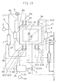
- Fig. 21 is a diagram showing an arrangement of an ozone producing apparatus for a process according to Embodiment 21 of the present invention.
- S5 to S11 are signal lines which connect the control circuit 15 with the ozone generator 1, circulating blower 3, cooling source 5, and switch valves 8a to 8d, respectively.
- S12 to S15 are also signal lines which connect the control circuit 15 with the heating source 6 and switch valves 8e to 8g, respectively.
- the remaining arrangements are identical with those of the apparatuses of Figs. 1, 5, 9, 13, and 17.
- the electricity supply condition to the apparatus is continuously monitored by the electricity supply condition monitor 14, the internal pressure in the adsorption/desorption tower 4 by the pressure gauge 16, and the internal temperature in the adsorption/desorption tower 4 by the thermometer 17, and based on these output signals, the control circuit 15 determines whether the apparatus is under an abnormal driving condition.
- a signal is sent to the switch valve 9 via the signal line S2 and based on this signal the opening/closing condition or opening degree is controlled at the switch valve 9.
- the condition of the apparatus is continued to be monitored also thereafter by the electricity supply condition monitor 14, pressure gauge 16 in the adsorption/desorption tower 4 and thermometer 17 in the adsorption/desorption tower 4, and when these values have returned to the preliminarily set driving condition ranges, the switch valve 9 is closed through the signal line S2, and the ozone generator 1, circulating blower 3, cooling source 5, heating source 6, and switch valves 8a to 8g are operated by the signal lines S5 to S15 to return the apparatus to the original driving condition.
- the electricity supply condition to the apparatus, and the pressure and temperature in the adsorption/desorption tower 4 are thus continuously monitored also after operating the switch valve 9 to perform suitable and safe measures when electricity supply to the apparatus is terminated or the pressure or temperature in the adsorption/desorption tower 4 has deviated from a suitable range for the driving condition and the apparatus is under an abnornal driving condition. In the case where these values return to predetermined normal ranges, the original driving condition is automatically assumed. With this arrangement, the apparatus can be safely operated without completely terminating the operation to cope with short time power failure or short-term and temporal abnormalities in pressure or temperature.
- Fig. 22 is a diagram showing an arrangement of an ozone producing apparatus for a process according to Embodiment 22 of the present invention.
- the apparatus of this embodiment is arranged in such a manner that the reducer storage 10 of Embodiment 21 is replaced by the filler 11 and the ozone decomposer 12 of Embodiment 2.
- the condition of the apparatus is continued to be monitored also thereafter by the electricity supply condition monitor 14, pressure gauge 16 in the adsorption/desorption tower 4 and thermometer 17 in the adsorption/desorption tower 4, and when these values have returned to the predetermined driving condition ranges, the switch valve 9 is closed through the signal line S2, and the ozone generator 1, circulating blower 3, cooling source 5, heating source 6, and switch valves 8a to 8g are operated by the signal lines S5 to S15 to return the apparatus to the original driving condition.
- the electricity supply condition to the apparatus, and the pressure and temperature in the adsorption/desorption tower 4 are thus continuously monitored also after operating the switch valve 9 to perform suitable and safe measures when electricity supply to the apparatus is terminated or the pressure or temperature in the adsorption/desorption tower 4 has deviated from a suitable range for the driving condition and the apparatus is under an abnormal driving condition. In the case where these values return to predetermined normal ranges, the original driving condition is automatically assumed. With this arrangement, the apparatus can be safely operated without completely terminating the operation to cope with short time power failure or short-term and temporal abnormalities in pressure or temperature.
- Fig. 23 is a diagram showing an arrangement of an ozone producing apparatus for a process according to Embodiment 23 of the present invention.
- the apparatus of this embodiment is arranged in such a manner that the control circuit 15 of Embodiment 19 is connected to the ozone generator 1, circulating blower 3, cooling source 5, heating source 6, and switch valves 8a to 8g, similarly to the previous Embodiments 21 and 22.
- the condition of the apparatus is continued to be monitored also thereafter by the electricity supply condition monitor 14, pressure gauge 16 in the adsorption/desorption tower 4 and thermometer 17 in the adsorption/desorption tower 4, and when these values have returned to the preliminarily set driving condition ranges, the switch valve 9 is closed through the signal line S2 and the ozone generator 1, circulating blower 3, cooling source 5, heating source 6, and switch valves 8a to 8g are operated by the signal lines S5 to S15 to return the apparatus to the original driving condition.
- the electricity supply condition to the apparatus, and the pressure and temperature in the adsorption/desorption tower 4 are thus continuously monitored also after operating the switch valve 9 to perform suitable and safe measures when electricity supply to the apparatus is terminated or the pressure or temperature in the adsorption/desorption tower 4 has deviated from a suitable range for the driving condition and the apparatus is under an abnormal driving condition. In the case where these values return to predetermined normal ranges, the original driving condition is automatically assumed. With this arrangement, the apparatus can be safely operated without completely terminating the operation to cope with short time power failure or short-term and temporal abnormalities in pressure or temperature.
- Fig. 24 is a diagram showing an arrangement of an ozone producing apparatus for a process according to Embodiment 24 of the present invention.
- the apparatus of this embodiment is arranged in such a manner that the control circuit 15 of Embodiment 20 is connected to the ozone generator 1, circulating blower 3, cooling source 5, heating source 6, and switch valves 8a to 8g, similarly to the previous Embodiments 21 and 22.
- the condition of the apparatus is continued to be monitored also thereafter by the electricity supply condition monitor 14, pressure gauge 16 in the adsorption/desorption tower 4 and thermometer 17 in the adsorption/desorption tower 4, and when these values have returned to the preliminarily set driving condition ranges, the switch valve 9 is closed through the signal line S2 and the ozone generator 1, circulating blower 3, cooling source 5, heating source 6, and switch valves 8a to 8g are operated by the signal lines S5 to S15 to return the apparatus to the original driving condition.
- the electricity supply condition to the apparatus, and the pressure and temperature in the adsorption/desorption tower 4 are thus continuously monitored also after operating the switch valve 9 to perform suitable and safe measures when electricity supply to the apparatus is terminated or the pressure or temperature in the adsorption/desorption tower 4 has deviated from a suitable range for the driving condition and the apparatus is under an abnormal driving condition. In the case where these values return to predetermined normal ranges, the original driving condition is automatically assumed. With this arrangement, the apparatus can be safely operated without completely terminating the operation to cope with short time power failure or short-term and temporal abnormalities in pressure or temperature.
Landscapes
- Chemical & Material Sciences (AREA)
- Organic Chemistry (AREA)
- Inorganic Chemistry (AREA)
- Oxygen, Ozone, And Oxides In General (AREA)
- Testing And Monitoring For Control Systems (AREA)
- Separation Of Gases By Adsorption (AREA)
- Feeding, Discharge, Calcimining, Fusing, And Gas-Generation Devices (AREA)
- Treating Waste Gases (AREA)
Claims (11)
- Verfahren zum Herstellen von Ozon, wobei das Verfahren folgende Schritte aufweist:- Erzeugen von ozonisiertem Sauerstoff unter Verwendung eines Ozongenerators;- Adsorbieren und Bevorraten von Ozon aus dem ozonisierten Sauerstoff unter Verwendung eines Adsorptions-/Desorptions-Turms (4);- Desorbieren des adsorbierten und bevorrateten Ozons für die Zuführung unter Verwendung einer Ozon-Desorptionseinrichtung;gekennzeichnet durch die folgenden Schritte:- Verbinden von Einrichtungen (10, 11, 12, 13, La, Lc) mit dem Adsorptions-/Desorptions-Turm (4) für die Bewältigung eines Stromausfalls und/oder einer Situation, in der die Vorrichtung in einem anomalen Betriebszustand ist, in dem der Druck und/oder die Temperatur in dem Adsorptions-/Desorptions-Turm von einem vorbestimmten Bereich abgewichen ist,- Öffnen eines Umschaltventils (9), wenn ein Stromausfall oder anomale Betriebsbedingungen festgestellt werden, und- Schließen des Umschaltventils (9), wenn der Betrieb des Adsorptions-/- Desorptions-Turms (4) in einen normalen Zustand zurückgekehrt ist.
- Verfahren nach Anspruch 1,
wobei die Einrichtungen (10, 11, 12, 13, La, Lc) zum Bewältigen eines Stromausfalls oder eines anomalen Betriebszustands mit dem Adsorptions-/Desorptions-Turm (4) durch ein Umschaltventil (9) verbunden sind, das geöffnet wird, wenn die Ozon erzeugende Vorrichtung einen Stromausfall erleidet und/oder wenn sich die Vorrichtung in einem anomalen Betriebszustand befindet, in dem der Druck und/oder die Temperatur in dem Adsorptions-/Desorptions-Turm (4) von einem vorbestimmten Bereich abgewichen sind, wobei das Umschaltventil (9) geschlossen wird, wenn der Betrieb des Adsorptions-/Desorptions-Turm in einen normalen Zustand zurückgekehrt ist. - Verfahren nach Anspruch 1 oder 2,
wobei Einrichtungen zum Bewältigen eines Stromausfalls oder eines anomalen Betriebszustands verwendet werden, die einen Reduktionsmittel-Speicher (10) zum Bevorraten von Reduktionsmittel in diesem aufweisen, wobei das Reduktionsmittel zum Reduzieren von Ozon zu Sauerstoff ausgelegt ist. - Verfahren nach Anspruch 1 oder 2,
wobei Einrichtungen zum Bewältigen eines Stromausfalls oder eines anomalen Betriebszustands verwendet werden, die einen mit einem Ozon adsorbierenden Mittel gefüllten Füllstoff (11) sowie eine Ozon-Abbaueinrichtung (12) aufweisen, die dazu ausgebildet sind, ozonhaltiges Gas aus dem Adsorptions-/Desorptions-Turm (4) zu behandeln. - Verfahren nach Anspruch 1 oder 2,
wobei Einrichtungen zum Bewältigen eines Stromausfalls oder eines anomalen Betriebszustands verwendet werden, die eine Wasserleitungseinrichtung (Lc) aufweisen, die mit dem Adsorptions-/Desorptions-Turm (4) verbunden ist (La) und auf der stromabwärtigen Seite des Ozon-Desorptionseinrichtung (7) angeordnet ist sowie dazu ausgebildet ist, Ozon aus ozonhaltigem Gas von dem Adsorptions-/- Desorptions-Turm (4) zu entfernen. - Verfahren nach Anspruch 1 oder 2,
wobei Einrichtungen zum Bewältigen eines Stromausfalls oder eines anomalen Betriebszustands verwendet werden, die einen Gasspeicher (13) aufweisen, der dazu ausgebildet ist, ozonhaltiges Gas von dem Adsorptions-/Desorptions-Turm (4) zu speichern. - Verfahren nach einem der Ansprüche 1 bis 6,
wobei das Verfahren die Feststellung eines Stromausfalls oder eines anomalen Betriebszustands unter Verwendung einer Stromversorgungs-Überwachungseinrichtung (14) umfaßt, wobei ein Steuersignal zum Steuern der Funktion des Umschaltventils (9) abgegeben wird, wenn ein Stromausfall oder ein anomaler Betriebszustand festgestellt worden ist. - Verfahren nach einem der Ansprüche 1 bis 7,
wobei das Verfahren das Messen eines Drucks in dem Adsorptions-/Desorptions-Turm (4) unter Verwendung einer Druckerfassungseinrichtung (16) umfaßt, wobei ein Steuersignal zum Steuern der Funktion des Umschaltventils (9) abgegeben wird, wenn der Druck von einem vorbestimmten Bereich abgewichen ist. - Verfahren nach einem der Ansprüche 1 bis 8,
wobei das Verfahren das Messen einer Temperatur in dem Adsorptions-/- Desorptions-Turm (4) unter Verwendung einer Temperaturerfassungseinrichtung (17) umfaßt, wobei ein Steuersignal zum Steuern der Funktion des Umschaltventils (9) abgegeben wird, wenn die Temperatur in dem Adsorptions-/- Desorptions-Turm (4) von einem vorbestimmten Bereich abgewichen ist. - Verfahren nach einem der Ansprüche 1 bis 9,
wobei eine Steuerschaltung (15) verwendet wird, die dazu ausgelegt ist, Überwachungssignale von einer Stromversorgungs-Überwachungseinrichtung (14), einer Temperaturerfassungseinrichtung (17) und einer Druckerfassungseinrichtung (16) zu empfangen, sowie ferner dazu ausgelegt ist, Steuersignale zu dem Ozongenerator (1), einem Umlaufgebläse (3) des Adsorptions-/Desorptions-Turms (4), einer Kühlquelle (5) des Adsorptions-/Desorptions-Turms (4), einer Heizquelle (6) des Adsorptions-/Desorptions-Turms (4), Umschaltventilen (8a bis 8g) dieser Komponenten und/oder dem Umschaltventil (9) der Einrichtungen für die Bewältigung eines Stromausfalls oder eines anomalen Betriebszustands zu schicken, um deren Betrieb zu steuern. - Verfahren nach einem der Ansprüche 1 bis 10,
wobei die elektrische Stromversorgung, der Druck und die Temperatur des Adsorptions-/Desorptions-Turms (4) kontinuierlich überwacht werden und das Verfahren automatisch zu dem ursprünglichen Betriebszustand zurückkehrt, wenn das Verfahren nach einem Stromausfall oder einem anomalen Betriebszustand in einen normalen Zustand zurückgekehrt ist.
Priority Applications (1)
| Application Number | Priority Date | Filing Date | Title |
|---|---|---|---|
| EP02016437A EP1253109A3 (de) | 1997-07-24 | 1998-07-07 | Vorrichtung zur Herstellung von Ozon |
Applications Claiming Priority (2)
| Application Number | Priority Date | Filing Date | Title |
|---|---|---|---|
| JP19843697A JPH1143308A (ja) | 1997-07-24 | 1997-07-24 | オゾン製造装置 |
| JP198436/97 | 1997-07-24 |
Related Child Applications (1)
| Application Number | Title | Priority Date | Filing Date |
|---|---|---|---|
| EP02016437A Division EP1253109A3 (de) | 1997-07-24 | 1998-07-07 | Vorrichtung zur Herstellung von Ozon |
Publications (2)
| Publication Number | Publication Date |
|---|---|
| EP0893401A1 EP0893401A1 (de) | 1999-01-27 |
| EP0893401B1 true EP0893401B1 (de) | 2006-05-17 |
Family
ID=16391061
Family Applications (2)
| Application Number | Title | Priority Date | Filing Date |
|---|---|---|---|
| EP98112593A Expired - Lifetime EP0893401B1 (de) | 1997-07-24 | 1998-07-07 | Verfahren zur Erzeugung von Ozon |
| EP02016437A Withdrawn EP1253109A3 (de) | 1997-07-24 | 1998-07-07 | Vorrichtung zur Herstellung von Ozon |
Family Applications After (1)
| Application Number | Title | Priority Date | Filing Date |
|---|---|---|---|
| EP02016437A Withdrawn EP1253109A3 (de) | 1997-07-24 | 1998-07-07 | Vorrichtung zur Herstellung von Ozon |
Country Status (5)
| Country | Link |
|---|---|
| US (1) | US6214298B1 (de) |
| EP (2) | EP0893401B1 (de) |
| JP (1) | JPH1143308A (de) |
| CA (1) | CA2242827C (de) |
| DE (1) | DE69834526T2 (de) |
Families Citing this family (7)
| Publication number | Priority date | Publication date | Assignee | Title |
|---|---|---|---|---|
| US20040136885A1 (en) * | 2003-01-09 | 2004-07-15 | Hogarth Derek J. | Apparatus and method for generating ozone |
| US7029637B2 (en) * | 2003-01-09 | 2006-04-18 | H203, Inc. | Apparatus for ozone production, employing line and grooved electrodes |
| JP4254751B2 (ja) * | 2005-06-17 | 2009-04-15 | トヨタ自動車株式会社 | 排気ガス浄化装置 |
| CN100402138C (zh) * | 2006-09-20 | 2008-07-16 | 吴相安 | 便携式功能型气体发生器 |
| US20200279681A1 (en) | 2018-12-27 | 2020-09-03 | Massachusetts Institute Of Technology | Variable-width, spiral-grooved, stacked-plate superconducting magnets and electrically conductive terminal blocks and related construction techniques |
| EP3950580A4 (de) * | 2019-03-29 | 2022-04-06 | Mitsubishi Electric Corporation | Vorrichtung und verfahren zur ozonzufuhr |
| CA3174309A1 (en) | 2020-05-20 | 2021-11-25 | Alexey Radovinsky | Techniques for distributing forces in high field magnets and related systems and methods |
Family Cites Families (10)
| Publication number | Priority date | Publication date | Assignee | Title |
|---|---|---|---|---|
| JPS523595A (en) | 1975-06-27 | 1977-01-12 | Mitsubishi Electric Corp | Ozonizer with oxygen recycle system |
| JPS592559B2 (ja) | 1978-11-02 | 1984-01-19 | 三菱電機株式会社 | 微生物除去装置 |
| JPS55158107A (en) | 1979-05-29 | 1980-12-09 | Mitsubishi Electric Corp | Oxygen recycling type ozone generating apparatus |
| US4552659A (en) | 1980-03-04 | 1985-11-12 | Mitsubishi Denki Kabushiki Kaisha | Apparatus for elimination of biofouling |
| US4453953A (en) * | 1981-05-12 | 1984-06-12 | Mitsubishi Denki Kabushiki Kaisha | Intermittent ozone feeding apparatus |
| DE3632937A1 (de) * | 1986-09-27 | 1988-03-31 | Bbc Brown Boveri & Cie | Verfahren zur erzeugung von ozon |
| CA2136265C (en) * | 1993-11-22 | 1999-07-27 | Masami Shimizu | Apparatus for generating and condensing ozone |
| US5810910A (en) * | 1995-10-06 | 1998-09-22 | Air Products And Chemicals, Inc. | Adsorbents for ozone recovery from gas mixtures |
| JP3769742B2 (ja) * | 1995-11-14 | 2006-04-26 | 石川島播磨重工業株式会社 | オゾン発生装置の制御方法 |
| JP3980091B2 (ja) * | 1996-03-01 | 2007-09-19 | 三菱電機株式会社 | オゾン貯蔵装置 |
-
1997
- 1997-07-24 JP JP19843697A patent/JPH1143308A/ja active Pending
-
1998
- 1998-07-07 EP EP98112593A patent/EP0893401B1/de not_active Expired - Lifetime
- 1998-07-07 DE DE69834526T patent/DE69834526T2/de not_active Expired - Lifetime
- 1998-07-07 EP EP02016437A patent/EP1253109A3/de not_active Withdrawn
- 1998-07-08 US US09/111,179 patent/US6214298B1/en not_active Expired - Lifetime
- 1998-07-09 CA CA002242827A patent/CA2242827C/en not_active Expired - Lifetime
Also Published As
| Publication number | Publication date |
|---|---|
| EP1253109A2 (de) | 2002-10-30 |
| DE69834526T2 (de) | 2007-05-03 |
| DE69834526D1 (de) | 2006-06-22 |
| CA2242827C (en) | 2002-03-26 |
| JPH1143308A (ja) | 1999-02-16 |
| EP0893401A1 (de) | 1999-01-27 |
| EP1253109A3 (de) | 2010-04-21 |
| CA2242827A1 (en) | 1999-01-24 |
| US6214298B1 (en) | 2001-04-10 |
Similar Documents
| Publication | Publication Date | Title |
|---|---|---|
| EP0517427B1 (de) | Verfahren und Apparat zum Konzentrieren von Chlorgas | |
| US5604047A (en) | Carbon monoxide removal method based on adsorption/steam desorption cycle | |
| US4462965A (en) | Intermittent ozonizing apparatus | |
| EP0792835A1 (de) | Verfahren und Vorrichtung zur Speicherung von Ozon | |
| CN102139181A (zh) | 用于选择性收集过程流出物的方法和设备 | |
| JP2008078140A (ja) | スタック停止時の追い出し(パージ)方法 | |
| JP2008525779A (ja) | ガス混合物から希ガスを回収する方法 | |
| EP0893401B1 (de) | Verfahren zur Erzeugung von Ozon | |
| CN117751209A (zh) | 用于运行电解设施的方法和电解设施 | |
| EP0988491A1 (de) | System mit hoher gas-speicher-fähigkeit und spendersystem | |
| EP1101732B1 (de) | Verfahren und Vorrichtung zur kontinuierlichen Erzeugung von hochkonzentriertem Ozongas | |
| JPH0747103B2 (ja) | 圧力変動吸着方法及び装置 | |
| JP2008523981A (ja) | 温度に基づく破過検出及び圧力揺動吸着システム及び同一物を有する燃料電池 | |
| US5955214A (en) | Carbon monoxide removal method based on a regenerable CO scavenger | |
| EP0893402B1 (de) | Ozonzufuhrvorrichtung und Verfahren | |
| EP0893404B1 (de) | Vorrichtung zur Herstellung von Ozon | |
| EP0893403B1 (de) | Vorrichtung zur Erzeugung von Ozon | |
| JP3769742B2 (ja) | オゾン発生装置の制御方法 | |
| JPH09142807A (ja) | オゾン濃縮貯蔵装置とその制御方法 | |
| JP5206547B2 (ja) | オゾン製造装置およびオゾンを製造する方法 | |
| JPH10182861A (ja) | フッ素処理装置および被処理物の表面処理方法 | |
| JP4451114B2 (ja) | 排ガス処理機能を備えた機能水製造装置 | |
| JP7630749B1 (ja) | オゾン供給装置およびオゾン供給装置の運転方法 | |
| AU7762898A (en) | Apparatus and method for treating the atmosphere contained in enclosed spaces | |
| JPH02234360A (ja) | 燃料電池発電システム |
Legal Events
| Date | Code | Title | Description |
|---|---|---|---|
| PUAI | Public reference made under article 153(3) epc to a published international application that has entered the european phase |
Free format text: ORIGINAL CODE: 0009012 |
|
| AK | Designated contracting states |
Kind code of ref document: A1 Designated state(s): DE FR GB |
|
| AX | Request for extension of the european patent |
Free format text: AL;LT;LV;MK;RO;SI |
|
| 17P | Request for examination filed |
Effective date: 19990413 |
|
| AKX | Designation fees paid |
Free format text: DE FR GB |
|
| 17Q | First examination report despatched |
Effective date: 19990909 |
|
| RTI1 | Title (correction) |
Free format text: OZONE PRODUCING PROCESS |
|
| GRAP | Despatch of communication of intention to grant a patent |
Free format text: ORIGINAL CODE: EPIDOSNIGR1 |
|
| GRAS | Grant fee paid |
Free format text: ORIGINAL CODE: EPIDOSNIGR3 |
|
| GRAA | (expected) grant |
Free format text: ORIGINAL CODE: 0009210 |
|
| RAP1 | Party data changed (applicant data changed or rights of an application transferred) |
Owner name: MITSUBISHI DENKI KABUSHIKI KAISHA |
|
| AK | Designated contracting states |
Kind code of ref document: B1 Designated state(s): DE FR GB |
|
| REG | Reference to a national code |
Ref country code: GB Ref legal event code: FG4D |
|
| REF | Corresponds to: |
Ref document number: 69834526 Country of ref document: DE Date of ref document: 20060622 Kind code of ref document: P |
|
| REG | Reference to a national code |
Ref country code: GB Ref legal event code: 727 |
|
| REG | Reference to a national code |
Ref country code: GB Ref legal event code: 727A |
|
| ET | Fr: translation filed | ||
| REG | Reference to a national code |
Ref country code: GB Ref legal event code: 727B |
|
| PLBE | No opposition filed within time limit |
Free format text: ORIGINAL CODE: 0009261 |
|
| STAA | Information on the status of an ep patent application or granted ep patent |
Free format text: STATUS: NO OPPOSITION FILED WITHIN TIME LIMIT |
|
| 26N | No opposition filed |
Effective date: 20070220 |
|
| REG | Reference to a national code |
Ref country code: GB Ref legal event code: 746 Effective date: 20110513 |
|
| REG | Reference to a national code |
Ref country code: DE Ref legal event code: R084 Ref document number: 69834526 Country of ref document: DE Effective date: 20110506 Ref country code: DE Ref legal event code: R084 Ref document number: 69834526 Country of ref document: DE Effective date: 20110704 Ref country code: DE Ref legal event code: R084 Ref document number: 69834526 Country of ref document: DE Effective date: 20110705 |
|
| PGFP | Annual fee paid to national office [announced via postgrant information from national office to epo] |
Ref country code: GB Payment date: 20120704 Year of fee payment: 15 |
|
| PGFP | Annual fee paid to national office [announced via postgrant information from national office to epo] |
Ref country code: DE Payment date: 20120704 Year of fee payment: 15 Ref country code: FR Payment date: 20120719 Year of fee payment: 15 |
|
| GBPC | Gb: european patent ceased through non-payment of renewal fee |
Effective date: 20130707 |
|
| REG | Reference to a national code |
Ref country code: FR Ref legal event code: ST Effective date: 20140331 |
|
| PG25 | Lapsed in a contracting state [announced via postgrant information from national office to epo] |
Ref country code: DE Free format text: LAPSE BECAUSE OF NON-PAYMENT OF DUE FEES Effective date: 20140201 Ref country code: GB Free format text: LAPSE BECAUSE OF NON-PAYMENT OF DUE FEES Effective date: 20130707 |
|
| REG | Reference to a national code |
Ref country code: DE Ref legal event code: R119 Ref document number: 69834526 Country of ref document: DE Effective date: 20140201 |
|
| PG25 | Lapsed in a contracting state [announced via postgrant information from national office to epo] |
Ref country code: FR Free format text: LAPSE BECAUSE OF NON-PAYMENT OF DUE FEES Effective date: 20130731 |