EP0893403A1 - Dispositif de production d'ozone - Google Patents
Dispositif de production d'ozone Download PDFInfo
- Publication number
- EP0893403A1 EP0893403A1 EP98112897A EP98112897A EP0893403A1 EP 0893403 A1 EP0893403 A1 EP 0893403A1 EP 98112897 A EP98112897 A EP 98112897A EP 98112897 A EP98112897 A EP 98112897A EP 0893403 A1 EP0893403 A1 EP 0893403A1
- Authority
- EP
- European Patent Office
- Prior art keywords
- ozone
- adsorption
- desorption
- oxygen
- desorption tower
- Prior art date
- Legal status (The legal status is an assumption and is not a legal conclusion. Google has not performed a legal analysis and makes no representation as to the accuracy of the status listed.)
- Granted
Links
Images






Classifications
-
- C—CHEMISTRY; METALLURGY
- C01—INORGANIC CHEMISTRY
- C01B—NON-METALLIC ELEMENTS; COMPOUNDS THEREOF; METALLOIDS OR COMPOUNDS THEREOF NOT COVERED BY SUBCLASS C01C
- C01B13/00—Oxygen; Ozone; Oxides or hydroxides in general
- C01B13/10—Preparation of ozone
-
- B—PERFORMING OPERATIONS; TRANSPORTING
- B01—PHYSICAL OR CHEMICAL PROCESSES OR APPARATUS IN GENERAL
- B01D—SEPARATION
- B01D53/00—Separation of gases or vapours; Recovering vapours of volatile solvents from gases; Chemical or biological purification of waste gases, e.g. engine exhaust gases, smoke, fumes, flue gases, aerosols
- B01D53/02—Separation of gases or vapours; Recovering vapours of volatile solvents from gases; Chemical or biological purification of waste gases, e.g. engine exhaust gases, smoke, fumes, flue gases, aerosols by adsorption, e.g. preparative gas chromatography
- B01D53/04—Separation of gases or vapours; Recovering vapours of volatile solvents from gases; Chemical or biological purification of waste gases, e.g. engine exhaust gases, smoke, fumes, flue gases, aerosols by adsorption, e.g. preparative gas chromatography with stationary adsorbents
-
- B—PERFORMING OPERATIONS; TRANSPORTING
- B01—PHYSICAL OR CHEMICAL PROCESSES OR APPARATUS IN GENERAL
- B01D—SEPARATION
- B01D53/00—Separation of gases or vapours; Recovering vapours of volatile solvents from gases; Chemical or biological purification of waste gases, e.g. engine exhaust gases, smoke, fumes, flue gases, aerosols
- B01D53/02—Separation of gases or vapours; Recovering vapours of volatile solvents from gases; Chemical or biological purification of waste gases, e.g. engine exhaust gases, smoke, fumes, flue gases, aerosols by adsorption, e.g. preparative gas chromatography
- B01D53/04—Separation of gases or vapours; Recovering vapours of volatile solvents from gases; Chemical or biological purification of waste gases, e.g. engine exhaust gases, smoke, fumes, flue gases, aerosols by adsorption, e.g. preparative gas chromatography with stationary adsorbents
- B01D53/0454—Controlling adsorption
-
- B—PERFORMING OPERATIONS; TRANSPORTING
- B01—PHYSICAL OR CHEMICAL PROCESSES OR APPARATUS IN GENERAL
- B01D—SEPARATION
- B01D2256/00—Main component in the product gas stream after treatment
- B01D2256/14—Ozone
-
- B—PERFORMING OPERATIONS; TRANSPORTING
- B01—PHYSICAL OR CHEMICAL PROCESSES OR APPARATUS IN GENERAL
- B01D—SEPARATION
- B01D2257/00—Components to be removed
- B01D2257/10—Single element gases other than halogens
- B01D2257/106—Ozone
Definitions
- the present invention relates to an ozone producing apparatus. More particularly, it relates to an ozone producing apparatus for continuously producing ozone and storing the same in an adsorbed state and supplying the ozone when required by desorbing (separating) the same.
- An ozone producing apparatus employing such an ozone producing method is known to comprise the following components as shown in Fig. 10: an ozone generator 50, an oxygen supply source 51, a circulating blower 52, an adsorption/desorption tower 53, a cooling source 54, a heating source 55, a water flow ejector 56 and switch valves 57a to 57g.
- the adsorption/desorption tower 53 is of double cylinder type of which inner cylinder is filled with an ozone absorbent and an outer cylinder with heating medium. Silica gel might be employed as the ozone absorbent, and ethylene glycol or alcohol group as the heating medium.
- the circulating blower 52, ozone generator 50 and adsorption/desorption tower 53 constitute, in this order, a circulating system.
- Oxygen is supplied by the oxygen supply source 51 so that the pressure in the circulating system is always constant. In this case, the pressure is normally maintained at 1.5 kg/cm 2 .
- oxygen is made to flow in the circulating system by the circulating blower 52 while the switch valves 57c and 57d are in an opened condition, a part of the oxygen is converted into ozone to generate an ozonized oxygen while passing through the discharge space of the ozone generator 50, and the ozonized oxygen is then transferred to the adsorption/desorption tower 53.
- the adsorbent in the adsorption/desorption tower 53 selectively adsorbs ozone, and the remaining oxygen is returned to the circulating blower 52 through the switch valve 57c. Oxygen which has been consumed as ozone to be absorbed is supplemented through the oxygen supply source 51. Since the adsorbent assumes a property that adsorption capacity of ozone varies depending on temperature, the absorbent is cooled by the cooling source 54 to not more than -30°C. That is, the lower the temperature becomes, an amount of ozone absorption increases, while the higher the temperature becomes, it decreases. Accordingly, the temperature of absorbent is raised by the heating source 55 when desorbing ozone.
- the desorbing operation of ozone is performed.
- operations of the ozone generator 50, circulating blower 52 and cooling source 54 are terminated and the switch valves 57a to 57d are closed.
- the heating source 55 and water flow ejector 56 start their operation and switch valves 57e to 57g are opened.
- temperature of the adsorbent is raised by applying heat through the heating source 55 so that ozone which has been adsorbed by the adsorbent can easily be desorbed therefrom
- ozone is dispersed into water in the water flow ejector 56 to be dissolved and sent to, as ozone water, places where it is used.
- the present invention has been made in view of the above circumstances, and it is an object of the present invention to provide an economical ozone producing apparatus which is capable of decreasing the amount of energy required at the time of storing ozone, and with which little byproducts such as oxidants are generated by enabling definite ozone injection, that is, taking out stored ozone of high density as much as possible in a short time.
- the ozone producing apparatus comprises an ozone generator for generating ozonized oxygen, an adsorption/desorption tower for adsorbing and storing ozone from the ozonized oxygen generated by the ozone generator, and an ozone desorbing means for desorbing adsorbed and stored ozone for supply, wherein the apparatus further includes an oxygen gas supply means for supplying oxygen to the adsorption/desorption tower at the time of desorption is started and an oxygen gas flow rate adjusting means for adjusting flow rate of the oxygen gas to be supplied.
- the ozone producing apparatus includes a gas control means for adjusting, when desorbing adsorbed and stored ozone, pressure in the adsorption/desorption tower to not more than the atmospheric pressure.
- the ozone producing apparatus includes a temperature control means for maintaining, when desorbing adsorbed and stored ozone, temperature in the adsorption/desorption tower to be a temperature at the time of adsorption and storage.
- the ozone producing apparatus comprises an ozone generator for generating ozonized oxygen, an adsorption/desorption tower for adsorbing and storing ozone from the ozonized oxygen generated by the ozone generator, and an ozone desorbing means for desorbing adsorbed and stored ozone for supply, wherein the apparatus further includes an exhausting means for exhausting gas in the adsorption/desorption tower when desorption is started.
- the ozone producing apparatus is characterized in that after exhausting gas within the adsorption/desorption tower, a small amount of oxygen is made to flow into the adsorption/desorption tower.
- the ozone producing apparatus comprises an ozone generator for generating ozonized oxygen, an adsorption/desorption tower for adsorbing and storing ozone from the ozonized oxygen generated by the ozone generator, and an ozone desorbing means for desorbing adsorbed and stored ozone for supply, wherein the apparatus includes a tank for storing desorbed ozone.
- the ozone producing apparatus comprises an ozone generator for generating ozonized oxygen, an adsorption/desorption tower for adsorbing and storing ozone from the ozonized oxygen generated by the ozone generator, and an ozone desorbing means for desorbing the adsorbed and stored ozone for supply, wherein the apparatus further include an ozone densitometer for measuring a density of desorbed ozone and a control circuit for sending a desorption terminating control signal for terminating the desorption when a measured value of the ozone density at the time of desorption has fallen to a predetermined value after having reached a maximum value.
- Fig. 1 is a diagram showing an arrangement of an ozone producing apparatus according to Embodiment 1 of the present invention
- Such an apparatus comprises, as shown in Fig. 1, an ozone generator 1 for generating ozonized oxygen, an oxygen supply source 2, a circulating blower 3, an adsorption/desorption tower 4, a cooling source 5, a heating source 6, a water flow ejector 7 which is an ozone desorbing means, switch valves 8a to 8g, a tank 9, which is an oxygen gas supply means for supplying oxygen gas to the adsorption/desorption tower for storing ozone, and an adjuster 10 which is an oxygen gas flow rate adjusting means for adjusting an amount of oxygen gas supplied from the oxygen gas supply tank 9 to the adsorption/desorption tower 4.
- the adsorption/desorption tower 4 is of double cylinder type wherein an inner cylinder is filled with an adsorbent and an outer cylinder is filled with a thermal medium. It is preferable to select an adsorbent having a low decomposing rate when it comes into contact with ozone.
- an adsorbent having a low decomposing rate when it comes into contact with ozone.
- silica gel, activated alumina or porous materials impregnated with fluorocarbon can be employed.
- ethylene glycol or alcohol group might be used as the thermal medium.
- the circulating blower 3, ozone generator 1 and adsorption/desorption tower 4 constitute, in this order, a single circulating system.
- Oxygen is supplied by the oxygen supply source 2 so that the pressure in the circulating system is always constant, for example 1.5 kg/cm 2 .
- oxygen is made to flow in the circulating system by the circulating blower 3 while the switch valves 8a to 8d are in an opened condition, a part of the oxygen is converted into ozone through silent discharge to generate an ozonized oxygen while passing through the discharge space of the ozone generator 1, and the ozonized oxygen is then transferred to the adsorption/desorption tower 4.
- the adsorbent in the adsorption/desorption tower 4 selectively adsorbs ozone, and the remaining oxygen is returned to the circulating blower 3 through the switch valve 8c.
- Oxygen which has been consumed as ozone is supplemented through the oxygen supply source 2. Since the adsorbent assumes a property that adsorption capacity of ozone increases if the adsorbent is cooled more, the cooling temperature is generally maintained by the cooling source 5 to not more than -40°C. Further, the higher the pressure in the circulating system becomes, the more efficiently ozone can be stored. However, in view of ozone generating efficiency and ozone storing efficiency, an excessive increase of pressure in the circulating system results in an increase in consumption of electricity at the time of storage so that it is desirable to maintain a pressure of about 5 kg/cm 2 G in maximum
- the desorbing operation of ozone is performed.
- operations of the ozone generator 1, circulating blower 3 and cooling source 5 are terminated and the switch valves 8a to 8d are closed.
- the water flow ejector 7 starts its operation and the switch valve 8f is opened.
- temperature of the adsorbent is raised by applying heat of not less than 10°C through the heating source 6 so that ozone which has been adsorbed by the adsorbent can easily be desorbed therefrom in a few minutes.
- oxygen gas is supplied from the oxygen gas supply tank 9 to the adsorption/desorption tower 4 via the oxygen gas flow rate adjuster 10.
- supplied oxygen is adsorbed on the surface of silica gel which serves as an adsorbent in the adsorption/desorption tower 4 so that a so-called gas substitution phenomenon occurs in which the supplied oxygen is adsorbed and in turn already adsorbed ozone is desorbed, and gas containing ozone of high density is aspirated by the water flow ejector 7.
- Oxygen gas to be supplied at the time of ozone desorption is supplied from a position on a side opposite to the side from which ozone is aspirated from the adsorption/desorption tower 4. That is, when ozone is aspirated from the bottom portion of the adsorption/desorption tower 4, oxygen gas is supplied from the top portion of the adsorption/desorption tower 4. With this arrangement, substitution of oxygen and ozone can be efficiently performed and ozone of high density can be supplied.
- the amount of oxygen supply at the time of desorption depends on the amount of filled adsorbent, it is possible to supply ozone gas of highest density by adjusting the oxygen gas supply amount by the oxygen gas flow rate adjuster 10 such that oxygen is completely substituted by ozone at the outlet of the adsorption/desorption tower 4.
- an arbitrary amount of ozone of an arbitrary density can be input within a specified period to perform efficient ozone injection
- ozone of high density can be injected also by omitting a temperature raising process of the adsorbent to eliminate the provision of a heating source and to decrease the amount of energy used for raising the temperature, whereby an economical ozone producing apparatus can be obtained.
- this embodiment has been explained by taking a case of a desorption terminating flow in which the switch valve 8f is closed, oxygen supply from the oxygen gas supply tank 9 is terminated, and operation of the water flow ejector 1 is terminated; however, water used for driving the water flow ejector 7 can also be prevented from invading into the adsorption/desorption tower 4 by employing a desorption terminating flow in which oxygen supply from the oxygen gas supply tank 9 is terminated, the switch valve 8f is closed, and operation of the water flow ejector 7 is terminated.
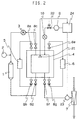
- Fig. 2 is a diagram showing an arrangement of an ozone producing apparatus according to Embodiment 2 of the present invention. Numerals of Fig. 2 which are identical with those of Embodiment 1 indicate identical or equivalent portions, and explanations thereof will thus be omitted.
- the apparatus includes a pressure sensor 21 for measuring a pressure in the adsorption/desorption tower 4 which is a gas control means, a pressure adjuster 22 for adjusting a supplying pressure of oxygen gas which is supplied from the oxygen gas supply tank 9 to the adsorption/desorption tower 4, a flow rate controller 23 for adjusting an ozone gas flow rate which is aspirated by the water flow ejector 7, and a pressure controller 24 for controlling, upon receipt of a signal from the pressure sensor 21, operations of the pressure adjuster 22, flow rate controller 23 and oxygen gas flow rate adjuster 10.
- the desorbing operation is performed.
- the desorbing operation operations of the ozone generator 1, the circulating blower 3 and the cooling source 5 are terminated and the switch valves 8a to 8d are closed.
- the water flow ejector 7 starts its operation and switch valves 8e to 8g are operated.
- temperature of the adsorbent is raised by applying heat of not less than 10°C through the heating source 6 so that ozone which has been adsorbed by the adsorbent can easily be desorbed therefrom in a few minutes.
- oxygen gas is supplied from the oxygen gas supply tank 9 to the adsorption/desorption tower 4 via the oxygen gas flow rate adjuster 10.
- Ozone injection is performed for a specified time, and when the process is completed, the switch valve 8f is closed, the oxygen supply from the oxygen gas supply tank 9 is terminated and the operation of the water flow ejector 7 is terminated.
- the process returns to the initial adsorbing operation and is continuously repeated.
- the amount of ozone which is again adsorbed after being desorbed by substitution with oxygen can be further decreased when the pressure in the adsorption/desorption tower 4 is lowered. That is, the amount of re-adsorbed ozone can be decreased by making the pressure in the adsorption/desorption tower 4 to less than the atmospheric pressure and thus to be in a negative pressure state.
- the pressure controller 24 controls operations of the pressure adjuster 22, flow rate controller 23 and oxygen gas flow rate adjuster 10 upon receipt of an electric signal from the pressure sensor 21 such that the pressure in the adsorption/desorption tower 4 is decreased as much as possible with maintaining a constant amount of oxygen gas supply to the adsorption/desoprtion tower 4. That is, ozone can be efficiently desorbed by decreasing the pressure of the supplied oxygen gas by means of the pressure adjuster 22 and by making the amount of supplied oxygen gas smaller than the amount of desorbed ozone gas.
- the pressure sensor 21 is disposed at a position which is remotest from a position at which ozone is aspirated by the water flow ejector 7. With this arrangement, all of the adsorbent in the adsorption/desorption tower 4 can be maintained at a pressure which is less than the atmospheric pressure, whereby ozone can be efficiently desorbed. Equivalent effects can be obtained by disposing the pressure sensor 21 in a downstream side of the oxygen gas flow rate adjuster 10. Further, a plurality of pressure sensors 21 might be used to perform precise control.
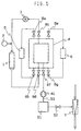
- Fig. 3 is a diagram showing an arrangement of an ozone producing apparatus according to Embodiment 3 of the present invention Numerals of Fig. 3 which are identical with those of Embodiment 1 indicate identical or equivalent portions, and explanations thereof will thus be omitted.
- the apparatus includes a temperature control means comprising a temperature sensor 31 for measuring a temperature in the adsorption/desorption tower 4 and a temperature controller 32 for controlling operations of the cooling source 5 upon receipt of a signal from the temperature sensor 31.
- the desorbing operation is performed.
- operations of the ozone generator 1 and circulating blower 3 are terminated, and switch valves 8a to 8d are closed.
- the water flow ejector 7 starts its operation and the switch valve 8f is opened.
- oxygen gas is supplied from the oxygen gas supply tank 9 to the adsorption/desorption tower 4 via the oxygen gas flow rate adjuster 10.
- Ozone injection is performed for a specified time, and when the process is completed, the switch valve 8f is closed, oxygen supply from the oxygen gas supply tank 9 is terminated and operation of the water flow ejector 7 is terminated.
- the process returns to the initial adsorbing operation and is continuously repeated.
- the temperature of silica gel which is employed as the ozone adsorbent drops once, since endothermic amount by desorption of ozone becomes larger than exothermic amount by adsorption of ozone.
- the temperature of silica gel is raised again by heat released from the adsorption/desorption tower 4. In this way, the temperature varies in the desorbing process depending on the adsorption of oxygen, desorption of ozone and heat released from the adsorption/desorption tower.
- electric signal is sent from the temperature sensor 31 to the temperature controller 32 and operation or termination signal is sent from the temperature controller 32 to the cooling source 5 in order to maintain the temperature in the adsorption/desorption tower 4 to the temperature at the time of adsorption and storage. That is, the cooling source 5 repeats operation or termination thereof in this embodiment to make the temperature in the adsorption/desorption tower 4 to the temperature at the time of adsorption and storage, regardless whether an adsorbing process or a desorbing process is performed.
- the amount of energy required for heating or cooling can be decreased, and since the temperature in the adsorption/desorption tower 4 is delicately controlled by employing the temperature sensor 31, the amount of energy required for driving the cooling source 5 can be decreased, which results in a decrease of running costs.
- the temperature sensor 31 is disposed at a position which is closest to a position from which ozonized oxygen is supplied at the time of adsorbing ozone. With this arrangement, adsorption of ozone can be effectively performed. Further, a plurality of temperature sensors 31 might be used to perform precise control.
- Embodiment 1 in view of capability of desorbing stored ozone at a stroke to be of high density, it is preferable to supply oxygen gas having a temperature higher than that of the ozone adsorbent. That is, by supplying oxygen gas having a temperature which has not been controlled and thus being of room temperature level, ozone can be efficiently desorbed.
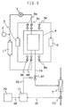
- Fig. 4 is a diagram showing an arrangement of an ozone producing apparatus according to Embodiment 4 of the present invention. Numerals of Fig. 4 which are identical with those of Embodiment 1 indicate identical or equivalent portions, and explanations thereof will thus be omitted.
- the apparatus includes an exhausting device 41 as an exhausting means for performing exhaustion in the adsorption/desorption tower 4 and a stop valve 42 provided on a piping 43 which connects the adsorption/desorption tower 4 and the exhausting device 41.
- the exhausting device 41 is immediately operated for a specified time after completion of the desorbing process, and the stop valve 42 is opened to exhaust oxygen gas remaining in the adsorption/desorption tower 4. Then, after operating the heating source 6 to raise temperature of the adsorbent or operating the water flow ejector 7, the adsorption/desorption tower 4 is decompressed to desorb the adsorbed ozone.
- the water flow ejector 7 might be operated after temperature of the adsorbent has been raised to perform adsorption.
- the desorbed ozone density can be made high and can also be made definite, since oxygen gas in the adsorption/desorption tower 4 can be preliminarily exhausted by operating the exhausting device 41 immediately before starting desorption
- oxygen which has not been adsorbed is preliminarily exhausted by the exhausting device 41 so that ozone which has been adsorbed is desorbed in the adsorption/desorption tower 4.
- Mixing a small amount of oxygen thereto causes mingling of oxygen to a prevailing ozone atmosphere and thus disturbs adsorption equilibrium of ozone with respect to the adsorbent, and the desorbing speed of adsorbed ozone is increased.
- adsorbed ozone can be desorbed at one stroke by injecting a small amount of oxygen to the adsorption/desorption tower 4 after exhausting gas in the adsorption/desorption tower 4, whereby the density of desorbed ozone can be made high and can further be made definite.
- Fig. 5 is a diagram showing an arrangement of an ozone producing apparatus according to Embodiment 5 of the present invention. Numerals of Fig. 5 that are identical with those of Embodiment 1 indicate identical or equivalent portions, and explanations thereof will thus be omitted.
- Numeral 51 denotes a tank for temporarily storing gas exhausted from the exhausting device 41, and 52 a switch valve. These are provided to a piping 53 which connects the exhausting device 41, tank 51, switch valve 52, adsorption/desorption tower 4, switch valve 8f and the water flow ejector 7.
- the heating source 6 is operated when entering the desorption process, ozone which has been adsorbed and stored by the adsorbent is desorbed at a high density by raising the temperature of the adsorbent, the switch valve 8f is opened while the switch valve 52 remains closed, and the exhausting device 41 is operated to temporarily store ozone gas of high density in the tank 51 which has been desorbed and stored in the adsorption/desorption tower 4.
- the switch valve 8f is also closed and the exhausting device 41 is terminated, whereupon the water flow ejector 7 is operated and the switch valve 52 is opened to introduce ozone which has been temporarily stored in the tank 51 to the water flow ejector 7 which is then dispersed into the water to dissolve as ozone water to be sent for use.
- the apparatus of this embodiment is so arranged that ozone of high density which is desorbed at the initial stage of the desorbing process is temporarily stored in the tank and ozone is supplied to the water flow ejector 7 after equalizing the desorbed ozone density, there can be achieved an effect that a low densification of ozone which presents small slime adhesion prevention effects in the latter half of the desorbing process as in a conventional apparatus can be eliminated.
- Fig. 6 is a diagram showing an arrangement of an ozone producing apparatus according to Embodiment 6 of the present invention
- numeral 61 denotes a switch valve attached to a piping 54 from a tank 51.
- the remaining arrangements are identical with those of the previous Embodiment 5.
- the heating source 6 is operated to heat the adsorbent and ozone adsorbed by the adsorbent in the adsorption/desorption tower 4 is desorbed to be of high density.
- the switch valve 8f is then opened while switch valves 52, 61 remain closed, and the exhausting device 41 is operated to temporarily store ozone gas of high density in the tank 51 which has been desorbed and stored in the adsorption/desorption tower 4.
- the switch valve 8f is also closed and the exhausting device 41 is terminated, whereupon the water flow ejector 7 is operated and the switch valve 52 is opened to introduce ozone which has been temporarily stored in the tank 51 to the water flow ejector 7 which is then dispersed into the water to dissolve as ozone water to be sent for use.
- the desorbed ozone density can be made high and made to be definite. Further, since ozone of high density which is desorbed at the initial stage of the desorbing process is temporarily stored in the tank and provided to the water flow ejector 7 after equalizing the desorbed ozone density, there can be achieved an effect that a low densification of ozone which presents small slime adhesion prevention effects in the latter half of the desorbing process as in a conventional apparatus can be eliminated.
- Fig. 7 is a diagram showing an arrangement of an ozone producing apparatus according to Embodiment 7 of the present invention.
- numeral 71 denotes a control circuit, 72 a setting means, and 73 an ozone densitometer attached to a piping 74.
- S1, S2 and S3 indicate signal lines which respectively connect the ozone densitometer 73 with the control circuit 71, the setting means 72 with the control circuit 71, and the switch valve 8f with the control circuit 71.
- Fig. 8 shows time changes in the density of desorbed ozone in a conventional apparatus.
- the desorbed ozone density assumes a pattern that it abruptly increases to reach a maximum density after starting the desorption and decreases thereafter.
- the desorbed ozone density is measured with the ozone densitometer 73 and a corresponding signal is sent to the control circuit 71 via the signal line S1.
- the control circuit 71 then performs comparison between the measured value and a set value which has been set by the setting means 72 and is supplied to the control circuit 71 via the signal line S2, and after the measured value for the desorbed ozone density has reached the maximum peak and decreases to the set density, a signal is sent to the switch valve 8f via the signal line S3 to close the switch valve 8f.
- an ozone densitometer for measuring the desorbed ozone gas density to obtain the ozone gas density at the time of desorption is terminated by sending a desorption terminating signal from the control circuit when the measured value for the desorbed ozone has dropped to a preliminarily set value while gradually decreasing in density after the desorbed ozone density has reached the maximum peak
- low densification of ozone which presents small slime adhesion prevention effects in the latter half of the desorbing process as in a conventional apparatus can be eliminated.
- Fig. 9 is a diagram showing an arrangement of an ozone producing apparatus according to Embodiment 8 of the present invention
- an ozone densitometer 73 is disposed at a preliminarily set location in the downstream side of a water flow ejector 7, and a signal line S1 connects the ozone densitometer 73 with a control circuit 71.
- the remaining arrangements are identical with those of Embodiment 7.
- the desorbed ozone density is measured by the ozone densitometer 73 as a density of ozone which is dissolved in water at a preliminarily set location in the downstream of the water flow ejector 7, and a corresponding signal is supplied to the control circuit 71 via the signal line S1.
- the control circuit 71 then performs comparison between the measured value and a set value which has been set by the setting means 72 and supplied to the control circuit 71 via the signal line S2, and after the measured value for the desorbed ozone density has reached the maximum peak and decreases to the set density, a signal is sent to the switch valve 8f via the signal line S3 to close the switch valve 8f.
- the speed of multiplication of microorganism and seaweed in the water which cause slime hazards varies depending on the water temperature or on the degree of pollution of the water, and the reactive speed of ozone also varies, the amount of required ozone also varies with seasonal fluctuations in water temperature or degree of pollution of the water.
- desorbed ozone is controlled by measuring the density of ozone dissolved in water, economical and efficient treatments can be performed with just sufficiently enough ozone even when environmental conditions of applied water or the like change.
- the ozone producing apparatus is so arranged as to aspirate ozone by means of the water flow ejector which is the ozone desorbing means and to simultaneously send oxygen gas from the oxygen gas supply means into the adsorption/desorption tower with adjusting the flow rate thereof, whereby there can be achieved effects that ozone injection can be made definite, that the apparatus is economical in the aspect of both initial and running costs, and that it presents great effects of preventing slime adhesion and can also limit generation of oxidants even when applied to sea water.
- the ozone producing apparatus is so arranged as to make pressure of oxygen gas supplied to the adsorption/desorption tower at the start of the desorbing process as small as possible and to make the amount of ozone aspirated by the water flow ejector which is the ozone desorbing means as large as possible, whereby there can be achieved effects that ozone can be effectively desorbed, that the apparatus is economical in the aspect of both initial and running costs, and that it presents great effects of preventing slime adhesion and can also limit generation of oxidants even when applied to sea water.
- the ozone producing apparatus is so arranged as to include a temperature control means for maintaining temperature in the adsorption/desorption tower at the time of desorption to the temperature at the time of adsorption and storage, whereby there can be achieved effects that the amount of required energy can be decreased, ozone injection can be performed as definite as possible, that the apparatus is economical in the aspect of both initial and running costs, and that it presents great effects of preventing slime adhesion and can also limit generation of oxidants even when applied to sea water.
- the ozone manufacturing apparatus is so arranged as to firstly exhaust gas in the adsorption/desorption tower at the beginning of desorption process and to make the temperature of the adsorbent rise or to decompress the interior of the adsorption/desorption tower before desorbing the adsorbed ozone, whereby there can be achieved effects that oxygen gas remaining in the adsorption/desorption tower after completion of the adsorbing process can be preliminarily eliminated, that the ozone density can be made definite, that the apparatus is economical in the aspect of both initial and running costs, and that it presents great effects of preventing slime adhesion and can also limit generation of oxidants even when applied to sea water.
- the ozone producing apparatus is so arranged as to inject a small amount of oxygen into the adsorption/desorption tower after exhausting gas in the adsorption/desorption tower, whereby there can be achieved effects that adsorbed ozone can be desorbed at a stroke, that the ozone density can be made definite, that the apparatus is economical in the aspect of both initial and running costs, and that it presents great effects of preventing slime adhesion and can also limit generation of oxidants even when applied to sea water.
- the ozone producing apparatus is so arranged as to temporarily store desorbed ozone in the tank for equalizing the desorbed ozone density, there can be achieved effects that low densification of desorbed ozone which presents small effects for preventing slime adhesion that used to occur in the latter half of the desorbing process in a conventional apparatus is eliminated, and that the apparatus is economical in the aspect of both initial and running costs and can also limit generation of oxidants even when applied to sea water.
- the ozone producing apparatus is so arranged as to include an ozone densitometer for measuring density of desorbed ozone wherein while measuring the ozone density during desorption, a desorption terminating control signal is sent from the control circuit for terminating the desorption when the measured value of the ozone density at the time of desorption has fallen to a predetermined value after having reached a maximum value, there can be achieved effects that low densification of desorbed ozone which presents small effects for preventing slime adhesion that used to occur in the latter half of the desorbing process in a conventional apparatus is eliminated, and that the apparatus is economical in the aspect of both initial and running costs and can also limit generation of oxidants even when applied to sea water.
Landscapes
- Chemical & Material Sciences (AREA)
- Organic Chemistry (AREA)
- Engineering & Computer Science (AREA)
- Analytical Chemistry (AREA)
- General Chemical & Material Sciences (AREA)
- Oil, Petroleum & Natural Gas (AREA)
- Chemical Kinetics & Catalysis (AREA)
- Inorganic Chemistry (AREA)
- Oxygen, Ozone, And Oxides In General (AREA)
- Separation Of Gases By Adsorption (AREA)
- Feeding, Discharge, Calcimining, Fusing, And Gas-Generation Devices (AREA)
Applications Claiming Priority (3)
| Application Number | Priority Date | Filing Date | Title |
|---|---|---|---|
| JP198435/97 | 1997-07-24 | ||
| JP9198435A JPH1143307A (ja) | 1997-07-24 | 1997-07-24 | オゾン製造装置 |
| JP19843597 | 1997-07-24 |
Publications (2)
| Publication Number | Publication Date |
|---|---|
| EP0893403A1 true EP0893403A1 (fr) | 1999-01-27 |
| EP0893403B1 EP0893403B1 (fr) | 2002-10-02 |
Family
ID=16391047
Family Applications (1)
| Application Number | Title | Priority Date | Filing Date |
|---|---|---|---|
| EP98112897A Expired - Lifetime EP0893403B1 (fr) | 1997-07-24 | 1998-07-10 | Dispositif de production d'ozone |
Country Status (5)
| Country | Link |
|---|---|
| US (1) | US6315962B1 (fr) |
| EP (1) | EP0893403B1 (fr) |
| JP (1) | JPH1143307A (fr) |
| CA (1) | CA2242999C (fr) |
| DE (1) | DE69808394T2 (fr) |
Cited By (2)
| Publication number | Priority date | Publication date | Assignee | Title |
|---|---|---|---|---|
| US6530976B2 (en) | 2000-03-02 | 2003-03-11 | The Kansai Electric Power Co., Inc. | Ozone storage method and ozone storage apparatus |
| WO2012156715A1 (fr) * | 2011-05-17 | 2012-11-22 | Bioquell Uk Limited | Appareil pour désinfecter des plaies à l'aide d'ozone, avec procédure de test de fuites |
Families Citing this family (6)
| Publication number | Priority date | Publication date | Assignee | Title |
|---|---|---|---|---|
| JP3670451B2 (ja) * | 1997-07-24 | 2005-07-13 | 三菱電機株式会社 | オゾン供給装置 |
| JP4491118B2 (ja) * | 2000-07-27 | 2010-06-30 | 関西電力株式会社 | オゾンの取出方法 |
| US6916359B2 (en) * | 2002-04-25 | 2005-07-12 | The Boc Group, Inc. | Ozone production processes |
| US7392657B2 (en) * | 2004-06-09 | 2008-07-01 | American Air Liquide, Inc. | Methods of dissolving ozone in a cryogen |
| JP6184645B1 (ja) * | 2016-01-28 | 2017-08-23 | 三菱電機株式会社 | オゾン供給装置およびオゾン供給方法 |
| CN112203974B (zh) * | 2018-06-07 | 2023-08-04 | 三菱电机株式会社 | 臭氧供给装置及臭氧供给方法 |
Citations (5)
| Publication number | Priority date | Publication date | Assignee | Title |
|---|---|---|---|---|
| JPS5235788A (en) * | 1975-09-17 | 1977-03-18 | Mitsubishi Electric Corp | Apparatus for producing ozone by cycling oxygen |
| JPS5424293A (en) * | 1977-07-26 | 1979-02-23 | Mitsubishi Electric Corp | Oxygen recycle ozone generating equipment |
| JPS57188406A (en) * | 1981-05-12 | 1982-11-19 | Mitsubishi Electric Corp | Intermittently feeding apparatus for ozone |
| JPS59193192A (ja) * | 1983-04-15 | 1984-11-01 | Mitsubishi Electric Corp | 間欠オゾン供給装置 |
| JPH09142808A (ja) * | 1995-11-14 | 1997-06-03 | Ishikawajima Harima Heavy Ind Co Ltd | オゾン発生装置の制御方法 |
Family Cites Families (7)
| Publication number | Priority date | Publication date | Assignee | Title |
|---|---|---|---|---|
| JPS523595A (en) | 1975-06-27 | 1977-01-12 | Mitsubishi Electric Corp | Ozonizer with oxygen recycle system |
| JPS592559B2 (ja) | 1978-11-02 | 1984-01-19 | 三菱電機株式会社 | 微生物除去装置 |
| JPS55158107A (en) | 1979-05-29 | 1980-12-09 | Mitsubishi Electric Corp | Oxygen recycling type ozone generating apparatus |
| US4552659A (en) | 1980-03-04 | 1985-11-12 | Mitsubishi Denki Kabushiki Kaisha | Apparatus for elimination of biofouling |
| US4453953A (en) | 1981-05-12 | 1984-06-12 | Mitsubishi Denki Kabushiki Kaisha | Intermittent ozone feeding apparatus |
| CA2136265C (fr) * | 1993-11-22 | 1999-07-27 | Masami Shimizu | Appareil de production et de condensation d'ozone |
| JP3980091B2 (ja) * | 1996-03-01 | 2007-09-19 | 三菱電機株式会社 | オゾン貯蔵装置 |
-
1997
- 1997-07-24 JP JP9198435A patent/JPH1143307A/ja active Pending
-
1998
- 1998-07-08 US US09/111,754 patent/US6315962B1/en not_active Expired - Lifetime
- 1998-07-10 DE DE69808394T patent/DE69808394T2/de not_active Expired - Lifetime
- 1998-07-10 EP EP98112897A patent/EP0893403B1/fr not_active Expired - Lifetime
- 1998-07-13 CA CA002242999A patent/CA2242999C/fr not_active Expired - Lifetime
Patent Citations (5)
| Publication number | Priority date | Publication date | Assignee | Title |
|---|---|---|---|---|
| JPS5235788A (en) * | 1975-09-17 | 1977-03-18 | Mitsubishi Electric Corp | Apparatus for producing ozone by cycling oxygen |
| JPS5424293A (en) * | 1977-07-26 | 1979-02-23 | Mitsubishi Electric Corp | Oxygen recycle ozone generating equipment |
| JPS57188406A (en) * | 1981-05-12 | 1982-11-19 | Mitsubishi Electric Corp | Intermittently feeding apparatus for ozone |
| JPS59193192A (ja) * | 1983-04-15 | 1984-11-01 | Mitsubishi Electric Corp | 間欠オゾン供給装置 |
| JPH09142808A (ja) * | 1995-11-14 | 1997-06-03 | Ishikawajima Harima Heavy Ind Co Ltd | オゾン発生装置の制御方法 |
Non-Patent Citations (5)
| Title |
|---|
| PATENT ABSTRACTS OF JAPAN vol. 001, no. 070 (C - 019) 8 July 1977 (1977-07-08) * |
| PATENT ABSTRACTS OF JAPAN vol. 007, no. 034 (C - 150) 10 February 1983 (1983-02-10) * |
| PATENT ABSTRACTS OF JAPAN vol. 009, no. 052 (C - 269) 6 March 1985 (1985-03-06) * |
| PATENT ABSTRACTS OF JAPAN vol. 097, no. 010 31 October 1997 (1997-10-31) * |
| PATENT ABSTRACTS OF JAPAN vol. 3, no. 50 (C - )<044> 27 April 1979 (1979-04-27) * |
Cited By (3)
| Publication number | Priority date | Publication date | Assignee | Title |
|---|---|---|---|---|
| US6530976B2 (en) | 2000-03-02 | 2003-03-11 | The Kansai Electric Power Co., Inc. | Ozone storage method and ozone storage apparatus |
| WO2012156715A1 (fr) * | 2011-05-17 | 2012-11-22 | Bioquell Uk Limited | Appareil pour désinfecter des plaies à l'aide d'ozone, avec procédure de test de fuites |
| CN103687629A (zh) * | 2011-05-17 | 2014-03-26 | 拜奥奎尔英国有限公司 | 具有泄漏测试程序的用于通过臭氧对伤口进行消毒的装置 |
Also Published As
| Publication number | Publication date |
|---|---|
| JPH1143307A (ja) | 1999-02-16 |
| CA2242999C (fr) | 2001-12-11 |
| US6315962B1 (en) | 2001-11-13 |
| DE69808394D1 (de) | 2002-11-07 |
| EP0893403B1 (fr) | 2002-10-02 |
| DE69808394T2 (de) | 2003-08-14 |
| CA2242999A1 (fr) | 1999-01-24 |
Similar Documents
| Publication | Publication Date | Title |
|---|---|---|
| US4462965A (en) | Intermittent ozonizing apparatus | |
| CA2198521C (fr) | Methode de stockage et systeme d'entreposage de l'ozone | |
| EP0893403B1 (fr) | Dispositif de production d'ozone | |
| CN102712859B (zh) | 可燃性气体浓缩装置 | |
| US6086772A (en) | Method and apparatus for preventing biofouling in cooling water system | |
| EP0893402B1 (fr) | Dispositif et procédé d'alimentation d'ozone | |
| EP0893404B1 (fr) | Dispositif de génération d'ozone | |
| US6214298B1 (en) | Ozone producing apparatus responsive to an abnormal driving condition | |
| EP0893400B1 (fr) | Dispositif d'alimentation d'ozone | |
| US6537508B1 (en) | Electric energy converting/storing system | |
| JPS6356163B2 (fr) | ||
| JP5020151B2 (ja) | オゾン製造装置およびオゾン製造方法 | |
| JP4545481B2 (ja) | オゾン供給装置 | |
| JP3087572B2 (ja) | オゾン発生供給装置 | |
| JPS63147803A (ja) | 間歇オゾン供給装置 | |
| JPS61231849A (ja) | タ−ビン発電機の冷却システム | |
| JP5206547B2 (ja) | オゾン製造装置およびオゾンを製造する方法 | |
| JPS6034483B2 (ja) | 間歇オゾン供給方法 | |
| JP2008038708A (ja) | キャニスタ | |
| JP2010083728A (ja) | 空気によるオゾン脱着方法およびオゾン貯蔵脱着装置 | |
| JPS60264310A (ja) | 間欠オゾン供給装置 | |
| JP2002121011A (ja) | オゾンの供給方法及び装置 | |
| JPH09156903A (ja) | 間欠オゾン供給装置及び方法 | |
| JPS6313928B2 (fr) | ||
| JPH05305290A (ja) | 生物付着防止装置 |
Legal Events
| Date | Code | Title | Description |
|---|---|---|---|
| PUAI | Public reference made under article 153(3) epc to a published international application that has entered the european phase |
Free format text: ORIGINAL CODE: 0009012 |
|
| AK | Designated contracting states |
Kind code of ref document: A1 Designated state(s): DE FR GB |
|
| AX | Request for extension of the european patent |
Free format text: AL;LT;LV;MK;RO;SI |
|
| RIN1 | Information on inventor provided before grant (corrected) |
Inventor name: OZAWA, TATEKI Inventor name: YUGE, HIROSHI Inventor name: AMITANI, HISAO Inventor name: NAKAYAMA, SHIGEKI Inventor name: HIROTSUJI, JUNJI Inventor name: TANIMURA, YASUHIRO |
|
| 17P | Request for examination filed |
Effective date: 19990526 |
|
| AKX | Designation fees paid |
Free format text: DE FR GB |
|
| 17Q | First examination report despatched |
Effective date: 20000410 |
|
| GRAG | Despatch of communication of intention to grant |
Free format text: ORIGINAL CODE: EPIDOS AGRA |
|
| GRAG | Despatch of communication of intention to grant |
Free format text: ORIGINAL CODE: EPIDOS AGRA |
|
| GRAH | Despatch of communication of intention to grant a patent |
Free format text: ORIGINAL CODE: EPIDOS IGRA |
|
| GRAH | Despatch of communication of intention to grant a patent |
Free format text: ORIGINAL CODE: EPIDOS IGRA |
|
| GRAA | (expected) grant |
Free format text: ORIGINAL CODE: 0009210 |
|
| AK | Designated contracting states |
Kind code of ref document: B1 Designated state(s): DE FR GB |
|
| REG | Reference to a national code |
Ref country code: GB Ref legal event code: FG4D |
|
| REF | Corresponds to: |
Ref document number: 69808394 Country of ref document: DE Date of ref document: 20021107 |
|
| REG | Reference to a national code |
Ref country code: GB Ref legal event code: 727 |
|
| REG | Reference to a national code |
Ref country code: GB Ref legal event code: 727A |
|
| ET | Fr: translation filed | ||
| REG | Reference to a national code |
Ref country code: GB Ref legal event code: 727A |
|
| PLBE | No opposition filed within time limit |
Free format text: ORIGINAL CODE: 0009261 |
|
| STAA | Information on the status of an ep patent application or granted ep patent |
Free format text: STATUS: NO OPPOSITION FILED WITHIN TIME LIMIT |
|
| 26N | No opposition filed |
Effective date: 20030703 |
|
| PGFP | Annual fee paid to national office [announced via postgrant information from national office to epo] |
Ref country code: DE Payment date: 20100707 Year of fee payment: 13 |
|
| REG | Reference to a national code |
Ref country code: GB Ref legal event code: 746 Effective date: 20110513 |
|
| REG | Reference to a national code |
Ref country code: DE Ref legal event code: R084 Ref document number: 69808394 Country of ref document: DE Effective date: 20110506 Ref country code: DE Ref legal event code: R084 Ref document number: 69808394 Country of ref document: DE Effective date: 20110701 Ref country code: DE Ref legal event code: R084 Ref document number: 69808394 Country of ref document: DE Effective date: 20110628 |
|
| PGFP | Annual fee paid to national office [announced via postgrant information from national office to epo] |
Ref country code: FR Payment date: 20110727 Year of fee payment: 14 |
|
| PGFP | Annual fee paid to national office [announced via postgrant information from national office to epo] |
Ref country code: GB Payment date: 20110706 Year of fee payment: 14 |
|
| GBPC | Gb: european patent ceased through non-payment of renewal fee |
Effective date: 20120710 |
|
| REG | Reference to a national code |
Ref country code: FR Ref legal event code: ST Effective date: 20130329 |
|
| PG25 | Lapsed in a contracting state [announced via postgrant information from national office to epo] |
Ref country code: GB Free format text: LAPSE BECAUSE OF NON-PAYMENT OF DUE FEES Effective date: 20120710 Ref country code: FR Free format text: LAPSE BECAUSE OF NON-PAYMENT OF DUE FEES Effective date: 20120731 Ref country code: DE Free format text: LAPSE BECAUSE OF NON-PAYMENT OF DUE FEES Effective date: 20130201 |
|
| REG | Reference to a national code |
Ref country code: DE Ref legal event code: R119 Ref document number: 69808394 Country of ref document: DE Effective date: 20130201 |