EP0893544A1 - Spülvorrichtung, insbesondere für WC-Becken - Google Patents
Spülvorrichtung, insbesondere für WC-Becken Download PDFInfo
- Publication number
- EP0893544A1 EP0893544A1 EP97460027A EP97460027A EP0893544A1 EP 0893544 A1 EP0893544 A1 EP 0893544A1 EP 97460027 A EP97460027 A EP 97460027A EP 97460027 A EP97460027 A EP 97460027A EP 0893544 A1 EP0893544 A1 EP 0893544A1
- Authority
- EP
- European Patent Office
- Prior art keywords
- drum
- piston
- valve
- water
- float
- Prior art date
- Legal status (The legal status is an assumption and is not a legal conclusion. Google has not performed a legal analysis and makes no representation as to the accuracy of the status listed.)
- Withdrawn
Links
- 238000011010 flushing procedure Methods 0.000 title description 4
- XLYOFNOQVPJJNP-UHFFFAOYSA-N water Substances O XLYOFNOQVPJJNP-UHFFFAOYSA-N 0.000 claims abstract description 57
- 229910001868 water Inorganic materials 0.000 claims abstract description 57
- 238000013519 translation Methods 0.000 claims description 10
- 230000003578 releasing effect Effects 0.000 claims description 2
- 230000002441 reversible effect Effects 0.000 claims description 2
- 230000001105 regulatory effect Effects 0.000 abstract 1
- 240000008042 Zea mays Species 0.000 description 4
- 238000004140 cleaning Methods 0.000 description 3
- 230000000903 blocking effect Effects 0.000 description 2
- 230000000670 limiting effect Effects 0.000 description 2
- 230000036961 partial effect Effects 0.000 description 2
- 239000007787 solid Substances 0.000 description 2
- 238000007514 turning Methods 0.000 description 2
- 101100536354 Drosophila melanogaster tant gene Proteins 0.000 description 1
- 241000287107 Passer Species 0.000 description 1
- 230000002950 deficient Effects 0.000 description 1
- 238000011161 development Methods 0.000 description 1
- 230000000694 effects Effects 0.000 description 1
- 230000009975 flexible effect Effects 0.000 description 1
- 230000033001 locomotion Effects 0.000 description 1
- 238000012423 maintenance Methods 0.000 description 1
- 210000002445 nipple Anatomy 0.000 description 1
- 229940012982 picot Drugs 0.000 description 1
Images




Classifications
-
- E—FIXED CONSTRUCTIONS
- E03—WATER SUPPLY; SEWERAGE
- E03D—WATER-CLOSETS OR URINALS WITH FLUSHING DEVICES; FLUSHING VALVES THEREFOR
- E03D1/00—Water flushing devices with cisterns ; Setting up a range of flushing devices or water-closets; Combinations of several flushing devices
- E03D1/02—High-level flushing systems
- E03D1/14—Cisterns discharging variable quantities of water also cisterns with bell siphons in combination with flushing valves
- E03D1/142—Cisterns discharging variable quantities of water also cisterns with bell siphons in combination with flushing valves in cisterns with flushing valves
-
- E—FIXED CONSTRUCTIONS
- E03—WATER SUPPLY; SEWERAGE
- E03D—WATER-CLOSETS OR URINALS WITH FLUSHING DEVICES; FLUSHING VALVES THEREFOR
- E03D1/00—Water flushing devices with cisterns ; Setting up a range of flushing devices or water-closets; Combinations of several flushing devices
- E03D1/30—Valves for high or low level cisterns; Their arrangement ; Flushing mechanisms in the cistern, optionally with provisions for a pre-or a post- flushing and for cutting off the flushing mechanism in case of leakage
- E03D1/36—Associated working of inlet and outlet valves
Definitions
- the present invention relates to a flush, with water reserve adjustable, for example and in particular for toilet bowls.
- the present flush comprises, in accordance with the invention, additional elements, which will be described now and which allow it to not deliver, at each actuation of the zipper, only a determined portion and finely adjustable for the total mass of water contained in this tank 8.
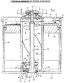
- a rotary drum 1 coaxial with the tank 8 and extending substantially over the entire height of this tank.
- this drum is actually composed of two concentric tubes, or ferrules, of which an internal tube 1A and an external tube 1B which are secured by an upper disc, or common cover, 18.
- the outer tube 1B rests in a coaxial circular groove 19 of the bottom 15 of the tank 8, this groove serving as a lower guide in rotation for the drum 1.
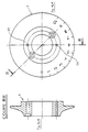
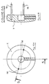
- the lower part of the tube 1B has large openings 20 (see also FIG. 7A), while the inner tube 1A, shorter than the outer tube 1B, does not completely reach bottom of tank 8.
- the diameter of the outer tube 1B is only slightly higher than that of the inner tube 1A, so as not to penalize the internal space of the drum 1.
- the drum 1 rotates, inter alia, with the cylindrical upper portion 2C of the pull rod 2.
- valve 2A and therefore the whole of the pull tab 2 is blocked in rotation by means of three radial rods 21 (see also Figures 10A and 10D) which are each respectively embedded (see in particular FIG. 6) in a slot, median and vertical, respective receiver 30 of three tilting stop pieces 4.
- the three stop pieces 4 are placed 120 degrees relative to each other. They can tilt backwards, with elastic return towards the front, in the vertical plane, but they are fixed in rotation in the horizontal plane. Their role and conformation will be explained below.
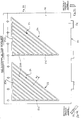
- the inner tube 1A is pierced by a few helical-shaped slots 22 for guiding a piston 3 (FIG. 1), these slots 22 being (FIG. 8A) all approximately parallel to one another. the other, to the parallelism corrections (necessary to allow the close) (these are not noticeable on this kind of drawing) and inclined relative to the axis of this tube 1A.
- This piston 3 and its role will be explained below.
- the tube external 1B comprises, on its external surface, two identical groups 23, 24 of grooves 25 for guiding the drum 1 in rotation.
- the float 5 comprises (FIGS. 1 and 13A) two other pins, external and radial, 28 and 29, for indexing this float in two vertical guide rails 13 provided on the inside of the tank 8 and consequently this float is fixed in rotation and mobile only in translation vertical, we can easily understand that the vertical movement of the float will have for effect, in fact only in its descent phase as will be explained below, to do the drum 1 simultaneously.
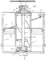
- FIGS. 1, 2, 5, 6, 11A, 11B, 12A to 12C we will now deal with the three tilting stop pieces 4 and elements with which they cooperate, i.e. on the one hand the valve 2A and on the other hand the piston 3.
- tilting parts 4 are fixed to the bottom 15 and are articulated on the latter around respective horizontal axes 31. They are each supported by a return spring 32 which tends to bring them forward, that is to say towards the axis 33 of the flush.
- Their active part is their part, or slice, before 34, that is to say that looking towards the zipper 2.
- valve 2A constitutes the lower part of the zipper 2, which will itself be described in detail below He receives, as mentioned above, the seal 12, and its upper part 40 (FIGS. 10A and 10D) forms a annular enlargement which includes the annular notch 60.
- the piston 3 is a solid body (FIG. 11A and 11B) which is movable in vertical translation and sliding along the central tubular part 2B of the zipper 2 but which is immobilized in rotation by the fact that its central orifice 41, by which it slides along the tubular middle part of the pull tab 2, has two flats 42, 43 respectively conjugated with two corresponding flats 44 45 (Figure 10D) of tube 2B.
- the piston 3 has, as indicated above, a part frustoconical 38 which allows it to open the three tilting stops 4.
- Three recesses 46 (FIG. 11A) allow free passage of water without loss of substantial charge.
- Three radial pins 47 are introduced into the slots inclined 22 of the tube 1A, so that the rotation, in one direction or the other, of the drum 1 causes the piston 3 to rise or fall.
- the rod 2C is integral with a washer 51, which has, on a portion of its circumference, a series of grooves formed by axial grooves 52, at number of eleven grooves in the example described here. Their role will be explained below.
- the upper part 2C and its partially grooved washer 51 pass through a washer 6 for adjusting the volume of water, which itself passes at through the cover 11 and which is fixed to the upper flange 18 of the drum 1 by two screws 54
- This washer 6 cooperates with a central orifice of the cover 11 to constitute the upper bearing level of the drum 1.
- a radial pin 55 (FIG. 1) is provided in the central orifice of the washer 6. It cooperates with the grooved washer 51, in the sense that, being unable enter one of the grooves 52 (FIGS. 10B and 1) only when it is aligned vertically with it, its position in the washer 6 is adjusted so that one can therefore only lift the pull tab 2 when the two internal fingers 26, 27 (FIG. 13A) for indexing the float 5 in the external tube 1B are found respectively opposite a descending indexing groove 25B (FIG. 9A) of the outer surface of this tube.
- the adjustment washer 6 has graduations, here from 0 to 10, which cooperate with a reference 56 of the cover 11 to adjust the volume of water discharged by the flush, for example liter per liter or even quarter liter per quarter liter.
- a button, or handle, for handling 7 covers the part upper of rod 2C.
- a radial nipple screw 57 enters the semicircular groove 53 of the rod 2C, which blocks this gripping button 7 in translation relative to the pull tab 2.
- this groove 53 allows the button 7 to rotate freely, in total only about half a turn, from this zipper 2.
- the piston rises to a height which depends on the angle of rotation of the drum 1, and therefore of the graduation chosen on the adjustment washer 6.
- the height position maximum possible of piston 3 this position corresponding to the graduation "10" of the washer 6 and therefore at a maximum rotation thereof.
- valve 2A then comes to open ( Figure 2) until it comes to rest on its seat maintenance in the open position which is constituted by the three aforementioned notches 36 ( Figure 12C) of the three tilting parts 4 (that the return force of the springs 32 to be brought forward, against the valve 2A, as soon as the piston 3 is raised).
- the water is then suddenly evacuated, through the drain orifice 16, towards the toilet bowl, or to any other user device.
- This simultaneous rotation of the cylinder 1 also causes the descent simultaneous piston 3, which is indexed by its pins 47 in the helical slots 22 of the inner tube 1A of the drum 1.
- the float 5, and therefore the water level only went down of a height corresponding to the descent of the piston 3, and therefore proportional to the initial angle (graduation "8") of rotation of button 7.
- the volume of water discharged by the drain port 16 is therefore also limited to a portion of the total water level of the tank 8, this portion being determined by this angle of rotation.
- this angle corresponds to the graduation "8" and if the graduation "10" corresponds to an ascent of the piston 3 for which all of the water in the tank is evacuated when the zipper 2 is then raised, we will only have evacuated eight tenths of the total volume of water in the tank.
- the arm 9 of the float 5 drives closing the tap 10, which closes the water supply.
- the toilet flush is then ready for a new use, with a volume of water to be drained which will be new chosen by the user, depending on the angle he will start with turn the operating knob 7 and therefore the selected scale on the washer adjustment 6.
- the indexing drum 1 could, instead consist of two concentric tubes 1A and 1B each provided with a index fingerprint, consisting of only one ferrule provided with a first index fingerprint, for example formed by grooves or slides, on its internal face and a second indexing imprint, too formed for example by grooves or slides, on its outer face.
Landscapes
- Health & Medical Sciences (AREA)
- Life Sciences & Earth Sciences (AREA)
- Engineering & Computer Science (AREA)
- Hydrology & Water Resources (AREA)
- Public Health (AREA)
- Water Supply & Treatment (AREA)
- Sanitary Device For Flush Toilet (AREA)
Priority Applications (1)
| Application Number | Priority Date | Filing Date | Title |
|---|---|---|---|
| EP97460027A EP0893544A1 (de) | 1997-07-22 | 1997-07-22 | Spülvorrichtung, insbesondere für WC-Becken |
Applications Claiming Priority (1)
| Application Number | Priority Date | Filing Date | Title |
|---|---|---|---|
| EP97460027A EP0893544A1 (de) | 1997-07-22 | 1997-07-22 | Spülvorrichtung, insbesondere für WC-Becken |
Publications (1)
| Publication Number | Publication Date |
|---|---|
| EP0893544A1 true EP0893544A1 (de) | 1999-01-27 |
Family
ID=8230013
Family Applications (1)
| Application Number | Title | Priority Date | Filing Date |
|---|---|---|---|
| EP97460027A Withdrawn EP0893544A1 (de) | 1997-07-22 | 1997-07-22 | Spülvorrichtung, insbesondere für WC-Becken |
Country Status (1)
| Country | Link |
|---|---|
| EP (1) | EP0893544A1 (de) |
Cited By (1)
| Publication number | Priority date | Publication date | Assignee | Title |
|---|---|---|---|---|
| WO2009068757A1 (fr) * | 2007-11-30 | 2009-06-04 | Societe Nouvelle Mpmp Sanitaire | Dispositif de vidange selectif pour sanitaires et son utilisation |
Citations (2)
| Publication number | Priority date | Publication date | Assignee | Title |
|---|---|---|---|---|
| US4486906A (en) * | 1983-06-09 | 1984-12-11 | Geberit Manufacturing, Inc. | Water-saving flush valve |
| US4881279A (en) * | 1989-03-20 | 1989-11-21 | Harney Donald E | Dual flush mechanism |
-
1997
- 1997-07-22 EP EP97460027A patent/EP0893544A1/de not_active Withdrawn
Patent Citations (2)
| Publication number | Priority date | Publication date | Assignee | Title |
|---|---|---|---|---|
| US4486906A (en) * | 1983-06-09 | 1984-12-11 | Geberit Manufacturing, Inc. | Water-saving flush valve |
| US4881279A (en) * | 1989-03-20 | 1989-11-21 | Harney Donald E | Dual flush mechanism |
Cited By (1)
| Publication number | Priority date | Publication date | Assignee | Title |
|---|---|---|---|---|
| WO2009068757A1 (fr) * | 2007-11-30 | 2009-06-04 | Societe Nouvelle Mpmp Sanitaire | Dispositif de vidange selectif pour sanitaires et son utilisation |
Similar Documents
| Publication | Publication Date | Title |
|---|---|---|
| BE1007146A3 (fr) | Moulin a condiment. | |
| EP3349901B1 (de) | Probenahmepipette mit einem steuerteil mit zweifacher funktion zum ausstossen eines konus und entriegelung des systems zur volumeneinstellung | |
| EP0520114B1 (de) | Unterbrechbarer Spülmechanismus mit gesicherter Minimalspülung | |
| EP0528740B1 (de) | Doppelt gesteuertes Spülmechanismus zur wahlweisen Teilmenge- oder Vollentleerung eines Spülkastens | |
| EP2542727B1 (de) | Leckerkennung bei einem spülblock | |
| EP1208782A1 (de) | Perkolationsvorrichtung | |
| FR2479731A1 (fr) | Dispositif pour la prehension et la mise en place de vis, de goupilles, de rivets, et d'articles similaires | |
| EP0578892B1 (de) | Spülwasseranlage zur Abgabe verschiedener, vorbestimmter Wassermengen | |
| FR2524790A1 (fr) | Cafetiere menagere | |
| WO2017178448A1 (fr) | Pipette pour le prelevement d'une plage etendue de volumes de liquide | |
| EP0522218B1 (de) | Druckknopfspülmechanismus mit eintauchbarem Körper | |
| EP0311542A1 (de) | Mechanismus zum Aktivieren der Spülung einer Toilette durch einen Druckknopf | |
| EP0685605A1 (de) | Toilettenspülungsvorrichtung mit doppeltem Betätigungsknopf zur Abgabe einer vorbestimmten Spülmenge | |
| FR2743831A1 (fr) | Chasse d'eau, en particulier pour cuvette de wc, et pouvant etre reglee pour fournir une quantite d'eau predeterminee et ajustable par paliers | |
| EP0124458B1 (de) | Spülvorrichtung für einen Spülkasten zu Betätigen durch einen Druckknopf | |
| EP0296632A2 (de) | Pulverspender | |
| EP3523488B1 (de) | Betätigungsvorrichtung für spülkasten mit drehwähler | |
| WO1997017503A1 (fr) | Dispositif a double commande de chasse de reservoir d'eau | |
| EP0381576B1 (de) | Ablaufstöpsel für sanitäre Einrichtungen | |
| EP0128847B1 (de) | Mechanismus zum Umkehren von Bewegungen und seine Anwendung für Dränagevorrichtungen für Spülbecken | |
| EP0553577B1 (de) | Toilettenspülungsbetätigungsvorrichtung mit regulierbarer Wassermenge notwendig für eine gute Reinigung des Beckens | |
| FR2665744A1 (fr) | Clapet pour la commande de l'ecoulement d'un liquide a partir d'un reservoir. | |
| FR2678968A1 (fr) | Dispositif de chasse d'eau destine a equiper un reservoir pour en commander la vidange au moins partielle. | |
| FR2594866A1 (fr) | Dispositif economiseur d'eau pour reservoir a deux capacites d'ecoulement | |
| FR2682140A1 (fr) | Dispositif controlant le volume d'eau libere par une chasse d'eau. |
Legal Events
| Date | Code | Title | Description |
|---|---|---|---|
| PUAI | Public reference made under article 153(3) epc to a published international application that has entered the european phase |
Free format text: ORIGINAL CODE: 0009012 |
|
| AK | Designated contracting states |
Kind code of ref document: A1 Designated state(s): DE GB NL |
|
| 17P | Request for examination filed |
Effective date: 19990701 |
|
| AKX | Designation fees paid |
Free format text: DE GB NL |
|
| 17Q | First examination report despatched |
Effective date: 19991129 |
|
| STAA | Information on the status of an ep patent application or granted ep patent |
Free format text: STATUS: THE APPLICATION IS DEEMED TO BE WITHDRAWN |
|
| 18D | Application deemed to be withdrawn |
Effective date: 20010201 |