EP0893545A2 - Caniveau à encastrer pour la pose dans le sol - Google Patents
Caniveau à encastrer pour la pose dans le sol Download PDFInfo
- Publication number
- EP0893545A2 EP0893545A2 EP98113551A EP98113551A EP0893545A2 EP 0893545 A2 EP0893545 A2 EP 0893545A2 EP 98113551 A EP98113551 A EP 98113551A EP 98113551 A EP98113551 A EP 98113551A EP 0893545 A2 EP0893545 A2 EP 0893545A2
- Authority
- EP
- European Patent Office
- Prior art keywords
- profile
- channel
- installation channel
- floor
- side wall
- Prior art date
- Legal status (The legal status is an assumption and is not a legal conclusion. Google has not performed a legal analysis and makes no representation as to the accuracy of the status listed.)
- Granted
Links
- 238000009434 installation Methods 0.000 claims description 32
- 150000001875 compounds Chemical class 0.000 claims description 10
- 238000005266 casting Methods 0.000 claims description 9
- 239000000463 material Substances 0.000 claims description 5
- 229910001220 stainless steel Inorganic materials 0.000 claims description 4
- 239000010935 stainless steel Substances 0.000 claims description 4
- 230000015572 biosynthetic process Effects 0.000 claims description 3
- 238000005755 formation reaction Methods 0.000 claims description 3
- 210000002105 tongue Anatomy 0.000 claims description 3
- 230000000149 penetrating effect Effects 0.000 claims 1
- 125000006850 spacer group Chemical group 0.000 abstract description 2
- 239000000853 adhesive Substances 0.000 description 3
- 230000001070 adhesive effect Effects 0.000 description 3
- 238000004140 cleaning Methods 0.000 description 3
- 239000002184 metal Substances 0.000 description 2
- 230000001154 acute effect Effects 0.000 description 1
- 238000004873 anchoring Methods 0.000 description 1
- 239000004568 cement Substances 0.000 description 1
- 230000002349 favourable effect Effects 0.000 description 1
- 238000009408 flooring Methods 0.000 description 1
- 238000003780 insertion Methods 0.000 description 1
- 230000037431 insertion Effects 0.000 description 1
- 239000004570 mortar (masonry) Substances 0.000 description 1
- 210000000056 organ Anatomy 0.000 description 1
- 238000004382 potting Methods 0.000 description 1
- 230000002787 reinforcement Effects 0.000 description 1
- 230000003014 reinforcing effect Effects 0.000 description 1
- 239000003351 stiffener Substances 0.000 description 1
- 229920003002 synthetic resin Polymers 0.000 description 1
- 239000000057 synthetic resin Substances 0.000 description 1
- XLYOFNOQVPJJNP-UHFFFAOYSA-N water Substances O XLYOFNOQVPJJNP-UHFFFAOYSA-N 0.000 description 1
- 238000003466 welding Methods 0.000 description 1
Images


Classifications
-
- E—FIXED CONSTRUCTIONS
- E03—WATER SUPPLY; SEWERAGE
- E03F—SEWERS; CESSPOOLS
- E03F3/00—Sewer pipe-line systems
- E03F3/04—Pipes or fittings specially adapted to sewers
- E03F3/046—Open sewage channels
-
- E—FIXED CONSTRUCTIONS
- E03—WATER SUPPLY; SEWERAGE
- E03F—SEWERS; CESSPOOLS
- E03F5/00—Sewerage structures
- E03F5/04—Gullies inlets, road sinks, floor drains with or without odour seals or sediment traps
- E03F2005/0412—Gullies inlets, road sinks, floor drains with or without odour seals or sediment traps with means for adjusting their position with respect to the surrounding surface
- E03F2005/0413—Gullies inlets, road sinks, floor drains with or without odour seals or sediment traps with means for adjusting their position with respect to the surrounding surface for height adjustment
-
- Y—GENERAL TAGGING OF NEW TECHNOLOGICAL DEVELOPMENTS; GENERAL TAGGING OF CROSS-SECTIONAL TECHNOLOGIES SPANNING OVER SEVERAL SECTIONS OF THE IPC; TECHNICAL SUBJECTS COVERED BY FORMER USPC CROSS-REFERENCE ART COLLECTIONS [XRACs] AND DIGESTS
- Y02—TECHNOLOGIES OR APPLICATIONS FOR MITIGATION OR ADAPTATION AGAINST CLIMATE CHANGE
- Y02A—TECHNOLOGIES FOR ADAPTATION TO CLIMATE CHANGE
- Y02A30/00—Adapting or protecting infrastructure or their operation
- Y02A30/60—Planning or developing urban green infrastructure
Definitions
- the invention relates to a gutter for laying in one Floor with a gutter profile that one of floor strips and side parts formed into a longitudinal slot polygon cross section tapering upwards from a sheet of material - especially from a stainless steel sheet - Has, lateral to this channel profile Attachments are connected.
- the cross section of such from DE 33 09 178 C2 as collecting channels for rooms in the food processing industry, in butchers, wineries or the like consists for example of two to each other in one Angular floor strips on the side wall strips connect that near the longitudinal slot in to each other pass over inclined ridge or gutter neck walls. As add-on elements reinforcement angles are provided on the ridge walls. These installation channels are on a bare floor or attached over recessed recesses of a floor.
- assembly aids serve the top edges of the gutter to keep at the level of the finished floor for so long until the channel is surrounded by a hardening casting compound and is kept embedded.
- assembly aids Pairs of vertical adjustment screws can be used Reach through elongated holes in the add-on elements and on them Nuts are adjusted; with the nuts you are in able to edge the gutter at floor level adjust, then cured in a bed of a Pour casting compound, the surface of the Bed advantageously level with the edges of the installation channel lies.
- the lateral attachment elements lead to better anchoring the installation channel in the floor, also one Load balancing in this.
- the goal is to design a channel of the type mentioned at the beginning that they are easy and quick to assemble adjusted and then safely in the casting compound can be anchored.
- Breakthroughs are provided, which an intimate connection of the Installation channel with the potting compound surrounding it in the position of use allow. It has also proven to be cheap Channel cross section from two inclined floor strips, from these parallel starting base walls as well to improve these adjoining side walls by that the ratio of the height of the base wall to the gutter height is about 1: 3.5 and the angle of inclination between the side wall and cross-sectional length about 20 °; the relationship should the axially parallel height of the side wall to the height of the Base wall with about 2: 1 can be selected. Thanks to these provisions the side walls become longer and steeper, i. H. the Checking and cleaning the gutter space becomes significant simplified.
- the side Add-on element a profile strip with three cross-sections zones inclined towards each other, namely with one of the profile channel adjacent connection zone, one of the breakthroughs containing intermediate zone and one - in itself from the Document known to the applicant from DE 94 11 477 U1, Elongated holes for stand screws, clip anchors or the like. Holding organs - fastening legs.
- the attachment element on the inclined Sidewall be fixed; then the angles between Connection zone and intermediate zone or between this and the mounting leg chosen with about 140 ° or 150 °.
- connection zone is located of the side add-on element on the axially parallel base wall fixed, and the angle between the connection zone as well Intermediate zone or between the latter and the fastening leg is approximately 120 ° or 150 °.
- This is also supposed to a folding strip is formed on the upper edge of the side wall be from which there is a staggered adhesive edge that runs parallel to the mounting leg of the attachment and can be used especially with thin beds.
- the side wall and base wall can also be used as an extension element project axially parallel wing webs at a distance from each other, the endward through a common angle profile - or at their lower edge are connected by a footplate.
- Another version contains as protruding from the channel profile Add-on element at least one axially parallel wing web, on which a footplate is formed vertically; latter can also be molded on both sides of a wing bridge be.
- the wing bridge should and / or its angle profile and / or its base plate with those Breakthroughs.
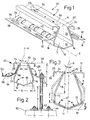
- Those side walls 18 are also - with the formation of a longitudinal slot 20 of width c from about 8 mm to 20 mm - from their respective base wall 14 from to the longitudinal axis A in one acute angle t inclined inwards of 21 ° and each end on a slot edge 22.
- These side folds 24 are after pouring a casting compound on the raw floor 10 in one - for reasons the clarity not shown - flooring embedded, and that of folding strips 24 and end legs 26 limited channel space 25 is then filled with casting compound.
- the surface of the bare floor 10 is only 28 indicated.
- the side walls are near this surface 28 18 of the channel profile 12 - at longer intervals e - through Cross bars 30 connected to each other.
- the thickness of the stainless steel sheet of the channel profile 12 is here between 1 mm and 3 mm, preferably 2 mm.
- a profile strip 32 is fixed in FIGS. 1, 2 - for example glued, soldered, welded or riveted - which is divided into three sections in cross section; an intermediate zone 35 adjoins a connecting zone 34 attached to the side wall 18 at an angle z of approximately 140 °, and an attachment leg 36 with elongated holes 38 at an angle z 1 of approximately 150 °, the longitudinal axes B of which parallel to the longitudinal axis E of the channel profile E 12 run.
- the elongated holes 38 are distributed at regular intervals on the strip-like fastening legs 36 over its entire leg length.
- the unit consisting of the channel profile 12 and the profile strips 32 on both sides is referred to below as the installation channel 40 for the sake of a better overview.
- At least one of the elongated holes 38 of the profile strip 32 is penetrated by an adjusting screw 42, with the Nuts 43 of the profile strips 32 - and thus the installation channel 40 - can be fixed.
- Each of the adjustment screws 42 protrudes from a base plate 44, which in turn with the raw floor 10, z. B. connected by screws is., cement, synthetic resins or the like - the whole Space to apply the hardening casting compound - e.g. B. Mortar, concrete and. a. the elongated holes 32 - as well as additional ones Breakthroughs 45 of the intermediate zone 35 - and thus causes one improved fixation of the channel profile 12 or the installation channel 40 in the casting compound.
- Fig. 3 can be seen from a dashed contour K the previously customary shape of channel profiles; whose angle t 1 between the cross-sectional longitudinal axis A and the side wall 19 of the contour K measures 35 °, the angle w 1 between the bottom strip 17 of the contour K and the cross-sectional longitudinal axis A here 65 °.
- the height f of the base walls measures 20 mm
- the axially parallel height f 1 of the side walls 18 also 40 mm
- the greater steepness of the new side walls 18 of the channel profile 12 according to the invention considerably improves the access of a cleaning water jet.
- the flanking profile strips 32 are attached to a base the parallel walls 14, ie, the connection zones 34 are parallel to the cross section longitudinal axis A; the angle z between the connecting zone 34 and the intermediate zone 35 here measures 120 °.
- an edge strip 27 parallel to the folding strips 24 is formed here as an adhesive edge for thin bed installation.
- the height h of the channel profile 12 a corresponds to 3.5 times the distance i - approximately 10 to 18 mm - between the adhesive edge or edge strip 27 on the one hand and the floor covering surface 28 on the other.
- the cross bars 30 of the channel sections 12,12 a respective installation of gutter 40.40 a serve - even during use of the channel profile 12,12 a - as a stiffener.
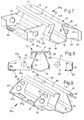
- the cuboid-like spacer 31 of the heavy-duty installation channel 40 b which can be seen in FIG. 7, on the other hand, can, if desired, be removed for better cleaning before use or after the installation of the installation channel 40 b .
- wing-like webs 46 are welded on the outside at a distance n from one another and their free web edges 47 are connected by an axially parallel angle profile 48.
- the latter is welded to the web edge 47 parallel to the cross-sectional longitudinal axis A and to the bottom web edge 47 a perpendicular thereto; the welding zones are designated 50.
- the installation channel 40 c of FIGS. 9, 10, which is heavier than the channels discussed above, is equipped on one side with the wing webs 46. At their lower edge of web 47 a, an outer foot plate 52 is attached with oval apertures 45 a.
- a short foot plate 52 a is formed on each wing web 46 a , the wing web 46 a thus has an L-shaped cross section. It ends at the bottom with the foot line 15 of the adjacent base wall 14 - in any case above the keel line 54 formed by the floor strips 16 - and offers at least one oval opening 45 a .
- the latter can - like the rest of the other installation channels - be replaced by an elongated hole 38.
- the footplate 52 a described above of the installation channel 40 e is the center piece of a longitudinally U-shaped side attachment element 56, which offers a wing web 46 a on both sides as a leg.
- the installation channel 40 f shown in FIGS. 15, 16 generally contains the channel profile 12 of FIGS. 1, 2.
- wing webs 46 b are pushed at intervals so that their lower edges 47 a in FIG. 16 are approximately aligned with that keel line 54.
- an insertion slot 58 runs in the wing webs 46 b , which widens conically towards the side wall 18 at 60 in order to be able to also detect the inclined intermediate zone 35; the outer fastening leg 36 of the profile strip 32 is arranged approximately in the middle of the web height q.
- the side profile strip 32 b of the installation channel 40 g of FIGS. 17, 18 is an angle piece attached to the side wall 18 with, between its two legs 33, molded out of these, tapering outwards, reinforcing the profile strips 32 b .
- the heavy built-in gutter 40 h of FIGS. 19, 20 consists of the profiled gutter 12 and sheet metal strips 64 connected on both sides and folded several times in a crenellated manner;
- U-like shaped areas 65 of the sheet metal strip 64 alternate with fastening sections 66 which protrude from the ends of the shaped area legs and are aligned with one another and which are attached to the side wall 18 of the channel profile 12.
- Tab tongues 67 which offer elongated holes 38, protrude from the lower edges of these fastening sections 66, at right angles to the cross-sectional axis A.
- the lower edge 68 of the cantilevered U-shaped area 65 extends to these tab tongues 67 at an angle s which is inclined downwards from here by almost 20 °; the lower edge 68 a of the central section of the U-shaped area 65 parallel to the channel longitudinal axis E lies approximately in a plane determined by the keel line 54.
Landscapes
- Health & Medical Sciences (AREA)
- Life Sciences & Earth Sciences (AREA)
- Engineering & Computer Science (AREA)
- Hydrology & Water Resources (AREA)
- Public Health (AREA)
- Water Supply & Treatment (AREA)
- Floor Finish (AREA)
- Sewage (AREA)
- Road Paving Structures (AREA)
Applications Claiming Priority (4)
| Application Number | Priority Date | Filing Date | Title |
|---|---|---|---|
| DE29713012U | 1997-07-23 | ||
| DE29713012 | 1997-07-23 | ||
| DE29714959U | 1997-08-21 | ||
| DE29714959U DE29714959U1 (de) | 1997-07-23 | 1997-08-21 | Einbaurinne zum Verlegen in einem Fußboden |
Publications (3)
| Publication Number | Publication Date |
|---|---|
| EP0893545A2 true EP0893545A2 (fr) | 1999-01-27 |
| EP0893545A3 EP0893545A3 (fr) | 1999-02-10 |
| EP0893545B1 EP0893545B1 (fr) | 2004-11-24 |
Family
ID=26060528
Family Applications (1)
| Application Number | Title | Priority Date | Filing Date |
|---|---|---|---|
| EP98113551A Expired - Lifetime EP0893545B1 (fr) | 1997-07-23 | 1998-07-21 | Caniveau à encastrer pour la pose dans le sol |
Country Status (2)
| Country | Link |
|---|---|
| EP (1) | EP0893545B1 (fr) |
| AT (1) | ATE283398T1 (fr) |
Cited By (10)
| Publication number | Priority date | Publication date | Assignee | Title |
|---|---|---|---|---|
| EP1170428A1 (fr) * | 2000-07-07 | 2002-01-09 | Stemar GmbH | Canal d'écoulement configuré comme profil de gouttière |
| EP1138840A3 (fr) * | 2000-03-21 | 2002-12-04 | Erich Altvater | Goulotte d'écoulement |
| US6905285B2 (en) * | 2000-04-29 | 2005-06-14 | Alumasc Limited | Slot drain |
| WO2005095725A1 (fr) * | 2004-04-01 | 2005-10-13 | Petrus Johannes Kuijper | Procede d'installation d'un systeme de conduite, systeme de conduite et element de support approprie pour la mise en oeuvre du procede |
| DE102007033824B4 (de) * | 2007-07-18 | 2010-12-02 | Trauthwein Entwässerungs- und Abscheidetechnik Industrievertretungen GmbH | Straßen- und Brückenentwässerungssystem und Vorrichtung zum Einbau des Systems |
| AT512480A1 (de) * | 2012-01-19 | 2013-08-15 | Aschl Roman Ing | Schlitzrinne |
| FR2996104A1 (fr) * | 2012-09-28 | 2014-04-04 | Isabelle Rolland | Tuyau d'evacuation des jus de lisier d'un couloir de raclage et couloir de raclage correspondant |
| EP2778305A1 (fr) * | 2013-03-11 | 2014-09-17 | Blücher Metal A/S | Caniveau ayant bords à arête vive |
| EP2765250B1 (fr) * | 2013-02-07 | 2020-06-10 | Dallmer GmbH & Co. KG | Rigole d'écoulement |
| DE102019126110A1 (de) * | 2019-09-27 | 2021-04-01 | ACO Severin Ahlmann GmbH & Co Kommanditgesellschaft | Entwässerungsrinne, Vorrichtung zur Höheneinstellung und Entwässerungsrinne mit einer Vorrichtung zur Höheneinstellung |
Families Citing this family (2)
| Publication number | Priority date | Publication date | Assignee | Title |
|---|---|---|---|---|
| DE202013005513U1 (de) | 2013-06-17 | 2014-09-18 | Wiedemann Gmbh | Rinne zum Verlegen in einem Fußboden |
| DE102018100782A1 (de) | 2017-12-22 | 2019-06-27 | Wiedemann Gmbh | Abflussrinne |
Citations (3)
| Publication number | Priority date | Publication date | Assignee | Title |
|---|---|---|---|---|
| US2180842A (en) | 1937-10-25 | 1939-11-21 | Walter G Winding | Form for concrete curb and gutter work |
| DE3309178A1 (de) | 1982-03-16 | 1983-09-29 | Wilhelm Hafner GmbH, 7752 Reichenau | Rinne insbesondere zum verlegen im fussboden eines massraumes |
| DE9411477U1 (de) | 1994-07-15 | 1994-11-03 | Wilhelm Hafner GmbH, 78479 Reichenau | Rinne zum Verlegen in einem Fußboden |
Family Cites Families (2)
| Publication number | Priority date | Publication date | Assignee | Title |
|---|---|---|---|---|
| DE8813624U1 (de) * | 1988-10-31 | 1988-12-22 | Wiedemann GmbH, 2250 Husum | Bodenentwässerungsrinne |
| DE9406004U1 (de) * | 1994-04-13 | 1994-08-11 | Wilhelm Hafner GmbH, 78479 Reichenau | Montagehilfe zum Verlegen von Rinnen |
-
1998
- 1998-07-21 AT AT98113551T patent/ATE283398T1/de not_active IP Right Cessation
- 1998-07-21 EP EP98113551A patent/EP0893545B1/fr not_active Expired - Lifetime
Patent Citations (3)
| Publication number | Priority date | Publication date | Assignee | Title |
|---|---|---|---|---|
| US2180842A (en) | 1937-10-25 | 1939-11-21 | Walter G Winding | Form for concrete curb and gutter work |
| DE3309178A1 (de) | 1982-03-16 | 1983-09-29 | Wilhelm Hafner GmbH, 7752 Reichenau | Rinne insbesondere zum verlegen im fussboden eines massraumes |
| DE9411477U1 (de) | 1994-07-15 | 1994-11-03 | Wilhelm Hafner GmbH, 78479 Reichenau | Rinne zum Verlegen in einem Fußboden |
Cited By (12)
| Publication number | Priority date | Publication date | Assignee | Title |
|---|---|---|---|---|
| EP1138840A3 (fr) * | 2000-03-21 | 2002-12-04 | Erich Altvater | Goulotte d'écoulement |
| US6905285B2 (en) * | 2000-04-29 | 2005-06-14 | Alumasc Limited | Slot drain |
| EP1170428A1 (fr) * | 2000-07-07 | 2002-01-09 | Stemar GmbH | Canal d'écoulement configuré comme profil de gouttière |
| WO2005095725A1 (fr) * | 2004-04-01 | 2005-10-13 | Petrus Johannes Kuijper | Procede d'installation d'un systeme de conduite, systeme de conduite et element de support approprie pour la mise en oeuvre du procede |
| DE102007033824B4 (de) * | 2007-07-18 | 2010-12-02 | Trauthwein Entwässerungs- und Abscheidetechnik Industrievertretungen GmbH | Straßen- und Brückenentwässerungssystem und Vorrichtung zum Einbau des Systems |
| AT512480A1 (de) * | 2012-01-19 | 2013-08-15 | Aschl Roman Ing | Schlitzrinne |
| FR2996104A1 (fr) * | 2012-09-28 | 2014-04-04 | Isabelle Rolland | Tuyau d'evacuation des jus de lisier d'un couloir de raclage et couloir de raclage correspondant |
| FR2996103A1 (fr) * | 2012-09-28 | 2014-04-04 | Isabelle Rolland | Bloc prefabrique en beton pour la construction d'un couloir de raclage dans une installation pour elevage d'animaux, procede de fabrication et couloir de raclage correspondants |
| EP2765250B1 (fr) * | 2013-02-07 | 2020-06-10 | Dallmer GmbH & Co. KG | Rigole d'écoulement |
| EP2778305A1 (fr) * | 2013-03-11 | 2014-09-17 | Blücher Metal A/S | Caniveau ayant bords à arête vive |
| EP2778305B1 (fr) | 2013-03-11 | 2018-10-31 | Blücher Metal A/S | Caniveau ayant bords à arête vive |
| DE102019126110A1 (de) * | 2019-09-27 | 2021-04-01 | ACO Severin Ahlmann GmbH & Co Kommanditgesellschaft | Entwässerungsrinne, Vorrichtung zur Höheneinstellung und Entwässerungsrinne mit einer Vorrichtung zur Höheneinstellung |
Also Published As
| Publication number | Publication date |
|---|---|
| EP0893545A3 (fr) | 1999-02-10 |
| EP0893545B1 (fr) | 2004-11-24 |
| ATE283398T1 (de) | 2004-12-15 |
Similar Documents
| Publication | Publication Date | Title |
|---|---|---|
| DE4244980B4 (de) | Balkon | |
| DD282044A5 (de) | Wandelementanordnung | |
| EP0893545B1 (fr) | Caniveau à encastrer pour la pose dans le sol | |
| EP0802287A2 (fr) | Grille de drainage réglable en hauteur | |
| EP0677622B1 (fr) | Caniveau pour la pose dans le sol | |
| DE3602962C2 (fr) | ||
| DE19511206C2 (de) | Hochbauentwässerungsrinne | |
| DE9411477U1 (de) | Rinne zum Verlegen in einem Fußboden | |
| DE2244596B2 (de) | Kabelwanne für elektrische Installationen | |
| DE9312522U1 (de) | Stützenfuß-System | |
| DE9219027U1 (de) | Trägerprofil für eine tragende Konstruktion eines Balkons | |
| DE29714959U1 (de) | Einbaurinne zum Verlegen in einem Fußboden | |
| EP0442130A1 (fr) | Elément de construction comme élément de jointoiement et/ou de dilatation et/ou de plaque en porte-à-faux pour bâtis de constructions armés | |
| DE10200527C2 (de) | Balkon | |
| DE9114733U1 (de) | Bausatz für eine Entwässerungsrinne | |
| DE3236235C2 (de) | Sicht- und Schallschutzwand | |
| EP1052339A2 (fr) | Bloc de maçonnerie pour la construction de murs sans joints de mortier et ancrage mural correspondant | |
| DE3426461C1 (de) | Dichtungsvorrichtung | |
| AT410233B (de) | Verbindungselement | |
| DE9411478U1 (de) | Rinne zum Verlegen in einem Fußboden | |
| DE1075696B (de) | Aus Stahlbetonfertigteilen in Form einer Bodenwanne und mehrerer rahmen und plattenförmiger Fertigteile zusammengesetzter Kabelschacht | |
| DE9406004U1 (de) | Montagehilfe zum Verlegen von Rinnen | |
| DE29501045U1 (de) | Vorgeständerter Balkonaufbau | |
| DE3004290A1 (de) | Abfluss zum abfuehren fluessiger medien und insbesonders schachtabdeckung bzw. rost dafuer | |
| DE7725729U1 (de) | Kreuzverbinder fuer kanalfoermige profile zur befestigung von deckenuntersichten |
Legal Events
| Date | Code | Title | Description |
|---|---|---|---|
| PUAI | Public reference made under article 153(3) epc to a published international application that has entered the european phase |
Free format text: ORIGINAL CODE: 0009012 |
|
| PUAL | Search report despatched |
Free format text: ORIGINAL CODE: 0009013 |
|
| AK | Designated contracting states |
Kind code of ref document: A2 Designated state(s): AT CH DE IT LI Kind code of ref document: A2 Designated state(s): DE ES FR IT NL |
|
| AX | Request for extension of the european patent |
Free format text: AL;LT;LV;MK;RO;SI |
|
| AK | Designated contracting states |
Kind code of ref document: A3 Designated state(s): AT BE CH CY DE DK ES FI FR GB GR IE IT LI LU MC NL PT SE |
|
| AX | Request for extension of the european patent |
Free format text: AL;LT;LV;MK;RO;SI |
|
| 17P | Request for examination filed |
Effective date: 19990809 Effective date: 19990805 |
|
| AKX | Designation fees paid |
Free format text: AT BE CH CY LI Free format text: AT BE CH CY DE LI |
|
| RBV | Designated contracting states (corrected) |
Designated state(s): AT CH DE IT LI |
|
| RBV | Designated contracting states (corrected) |
Designated state(s): DE ES FR IT NL |
|
| 17Q | First examination report despatched |
Effective date: 19990930 |
|
| REG | Reference to a national code |
Ref country code: DE Ref legal event code: 8566 |
|
| RAP1 | Party data changed (applicant data changed or rights of an application transferred) |
Owner name: BLUECHER GERMANY GMBH |
|
| 17Q | First examination report despatched |
Effective date: 20021015 |
|
| AK | Designated contracting states |
Designated state(s): DE ES FR IT NL |
|
| REF | Corresponds to: |
Ref document number: 69811298 Country of ref document: DE Date of ref document: 20030320 Kind code of ref document: P |
|
| NLV1 | Nl: lapsed or annulled due to failure to fulfill the requirements of art. 29p and 29m of the patents act | ||
| GRAP | Despatch of communication of intention to grant a patent |
Free format text: ORIGINAL CODE: EPIDOSNIGR1 |
|
| GRAS | Grant fee paid |
Free format text: ORIGINAL CODE: EPIDOSNIGR3 |
|
| GRAA | (expected) grant |
Free format text: ORIGINAL CODE: 0009210 |
|
| AK | Designated contracting states |
Kind code of ref document: B1 Designated state(s): AT CH DE IT LI |
|
| REG | Reference to a national code |
Ref country code: CH Ref legal event code: EP |
|
| REF | Corresponds to: |
Ref document number: 59812288 Country of ref document: DE Date of ref document: 20041230 Kind code of ref document: P |
|
| REG | Reference to a national code |
Ref country code: CH Ref legal event code: NV Representative=s name: HIEBSCH & PEEGE AG PATENTANWAELTE |
|
| PGFP | Annual fee paid to national office [announced via postgrant information from national office to epo] |
Ref country code: AT Payment date: 20050715 Year of fee payment: 8 |
|
| PGFP | Annual fee paid to national office [announced via postgrant information from national office to epo] |
Ref country code: CH Payment date: 20050718 Year of fee payment: 8 |
|
| PLBI | Opposition filed |
Free format text: ORIGINAL CODE: 0009260 |
|
| PLAX | Notice of opposition and request to file observation + time limit sent |
Free format text: ORIGINAL CODE: EPIDOSNOBS2 |
|
| PLAB | Opposition data, opponent's data or that of the opponent's representative modified |
Free format text: ORIGINAL CODE: 0009299OPPO |
|
| 26 | Opposition filed |
Opponent name: WIEDEMANN GMBH Effective date: 20050823 |
|
| PLAF | Information modified related to communication of a notice of opposition and request to file observations + time limit |
Free format text: ORIGINAL CODE: EPIDOSCOBS2 |
|
| PLBB | Reply of patent proprietor to notice(s) of opposition received |
Free format text: ORIGINAL CODE: EPIDOSNOBS3 |
|
| PG25 | Lapsed in a contracting state [announced via postgrant information from national office to epo] |
Ref country code: AT Free format text: LAPSE BECAUSE OF NON-PAYMENT OF DUE FEES Effective date: 20060721 |
|
| PG25 | Lapsed in a contracting state [announced via postgrant information from national office to epo] |
Ref country code: LI Free format text: LAPSE BECAUSE OF NON-PAYMENT OF DUE FEES Effective date: 20060731 Ref country code: CH Free format text: LAPSE BECAUSE OF NON-PAYMENT OF DUE FEES Effective date: 20060731 |
|
| PGFP | Annual fee paid to national office [announced via postgrant information from national office to epo] |
Ref country code: IT Payment date: 20060731 Year of fee payment: 9 |
|
| PLCK | Communication despatched that opposition was rejected |
Free format text: ORIGINAL CODE: EPIDOSNREJ1 |
|
| REG | Reference to a national code |
Ref country code: CH Ref legal event code: PL |
|
| PLBN | Opposition rejected |
Free format text: ORIGINAL CODE: 0009273 |
|
| STAA | Information on the status of an ep patent application or granted ep patent |
Free format text: STATUS: OPPOSITION REJECTED |
|
| 27O | Opposition rejected |
Effective date: 20060928 |
|
| PLAB | Opposition data, opponent's data or that of the opponent's representative modified |
Free format text: ORIGINAL CODE: 0009299OPPO |
|
| PG25 | Lapsed in a contracting state [announced via postgrant information from national office to epo] |
Ref country code: IT Free format text: LAPSE BECAUSE OF NON-PAYMENT OF DUE FEES Effective date: 20070721 |
|
| PGFP | Annual fee paid to national office [announced via postgrant information from national office to epo] |
Ref country code: DE Payment date: 20170728 Year of fee payment: 20 |
|
| REG | Reference to a national code |
Ref country code: DE Ref legal event code: R071 Ref document number: 59812288 Country of ref document: DE |