EP0893563B1 - Scharniervorrichtung, insbesondere für Kochflächendeckel - Google Patents
Scharniervorrichtung, insbesondere für Kochflächendeckel Download PDFInfo
- Publication number
- EP0893563B1 EP0893563B1 EP19970830389 EP97830389A EP0893563B1 EP 0893563 B1 EP0893563 B1 EP 0893563B1 EP 19970830389 EP19970830389 EP 19970830389 EP 97830389 A EP97830389 A EP 97830389A EP 0893563 B1 EP0893563 B1 EP 0893563B1
- Authority
- EP
- European Patent Office
- Prior art keywords
- support body
- hinging device
- seating
- hinging
- cooking surface
- Prior art date
- Legal status (The legal status is an assumption and is not a legal conclusion. Google has not performed a legal analysis and makes no representation as to the accuracy of the status listed.)
- Expired - Lifetime
Links
- 238000010411 cooking Methods 0.000 title claims description 29
- 239000000463 material Substances 0.000 description 5
- 238000004873 anchoring Methods 0.000 description 3
- 238000004519 manufacturing process Methods 0.000 description 3
- 239000004411 aluminium Substances 0.000 description 2
- 229910052782 aluminium Inorganic materials 0.000 description 2
- XAGFODPZIPBFFR-UHFFFAOYSA-N aluminium Chemical compound [Al] XAGFODPZIPBFFR-UHFFFAOYSA-N 0.000 description 2
- 239000011521 glass Substances 0.000 description 2
- 239000002184 metal Substances 0.000 description 2
- 229910052751 metal Inorganic materials 0.000 description 2
- 239000007769 metal material Substances 0.000 description 2
- 230000003534 oscillatory effect Effects 0.000 description 2
- 239000002699 waste material Substances 0.000 description 2
- 239000000853 adhesive Substances 0.000 description 1
- 230000001070 adhesive effect Effects 0.000 description 1
- 230000002411 adverse Effects 0.000 description 1
- 238000006243 chemical reaction Methods 0.000 description 1
- 238000004140 cleaning Methods 0.000 description 1
- 230000006835 compression Effects 0.000 description 1
- 238000007906 compression Methods 0.000 description 1
- 230000008878 coupling Effects 0.000 description 1
- 238000010168 coupling process Methods 0.000 description 1
- 238000005859 coupling reaction Methods 0.000 description 1
- 238000005520 cutting process Methods 0.000 description 1
- 238000012423 maintenance Methods 0.000 description 1
- 238000003801 milling Methods 0.000 description 1
- 229920001296 polysiloxane Polymers 0.000 description 1
Images


Classifications
-
- E—FIXED CONSTRUCTIONS
- E05—LOCKS; KEYS; WINDOW OR DOOR FITTINGS; SAFES
- E05D—HINGES OR SUSPENSION DEVICES FOR DOORS, WINDOWS OR WINGS
- E05D5/00—Construction of single parts, e.g. the parts for attachment
- E05D5/02—Parts for attachment, e.g. flaps
- E05D5/0215—Parts for attachment, e.g. flaps for attachment to profile members or the like
- E05D5/0223—Parts for attachment, e.g. flaps for attachment to profile members or the like with parts, e.g. screws, extending through the profile wall or engaging profile grooves
-
- E—FIXED CONSTRUCTIONS
- E05—LOCKS; KEYS; WINDOW OR DOOR FITTINGS; SAFES
- E05F—DEVICES FOR MOVING WINGS INTO OPEN OR CLOSED POSITION; CHECKS FOR WINGS; WING FITTINGS NOT OTHERWISE PROVIDED FOR, CONCERNED WITH THE FUNCTIONING OF THE WING
- E05F1/00—Closers or openers for wings, not otherwise provided for in this subclass
- E05F1/08—Closers or openers for wings, not otherwise provided for in this subclass spring-actuated, e.g. for horizontally sliding wings
- E05F1/10—Closers or openers for wings, not otherwise provided for in this subclass spring-actuated, e.g. for horizontally sliding wings for swinging wings, e.g. counterbalance
- E05F1/12—Mechanisms in the shape of hinges or pivots, operated by springs
- E05F1/1207—Mechanisms in the shape of hinges or pivots, operated by springs with a coil spring parallel with the pivot axis
- E05F1/1215—Mechanisms in the shape of hinges or pivots, operated by springs with a coil spring parallel with the pivot axis with a canted-coil torsion spring
Definitions
- the present invention relates to a hinging device, in particular to be used for oscillatably linking a covering element to a cooking surface.
- the device in reference can be commonly employed each time it is necessary to hinge an element of substantially flat conformation at a fixed structure.
- the cooking surfaces currently utilized are provided with a covering element, made of glass or metal for example, or another appropriate material, which is oscillatably movable between a first operating position in which it is disposed parallelly over the cooking surface, and a second operating position in which it is disposed perpendicularly to the cooking surface to enable free access to cookers.
- a covering element made of glass or metal for example, or another appropriate material, which is oscillatably movable between a first operating position in which it is disposed parallelly over the cooking surface, and a second operating position in which it is disposed perpendicularly to the cooking surface to enable free access to cookers.
- hinging devices are presently employed that are operatively interposed between a perimetric edge of the covering element and an attachment portion of the cooking surface usually situated at a rear region of said cooking surface.
- traditional hinging devices are comprised of a tubular body arranged to extend along the perimetric edge of the covering element and having a longitudinal housing adapted to receive said lower edge in engagement.
- a casing arranged to receive a rotating pin which is then fastened, by means of a small metal base for example, to the corresponding attachment region arranged on the cooking surface.
- a torsion or compression spring of such a stiffness that a predetermined return force of the covering element towards its second operating position perpendicular to the cooking surface is ensured.
- the tubular body is usually made of a metal material, and preferably aluminium.
- a further adverse aspect of traditional hinging devices is the great structural weight and bulkiness that these devices have, mainly due to the presence of said tubular body.
- This hinging device for doors or windows comprises a support body connected to a perimetric edge of a window frame and a pivoting member formed by a tubular casing receiving inside a rotating pin and vertically supported by a new shaped element which, on its turn, is connected to a fixed structure.
- the tubular body is connected to the support body by means of a grip portion which matches an anchoring portion of the window frame.
- a grip portion and the anchoring portion are connected the one with the other by means of a screw between the grip portion and the anchoring portion.
- the main object of the present invention is to overcome all drawbacks and operating limits mentioned above by providing a hinging device that is such shaped that easy adjustment of the position of the hinging points is made possible, while at the same time being of great structural simplicity and, as a result, of easy accomplishment at greatly contained production costs as compared with traditional devices.
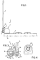
- a hinging device in particular for covering elements of cooking surfaces in accordance with the present invention has been generally identified by reference numeral 1.
- the hinging device 1 is operatively interposed between a cooking surface 2 and a covering element 3 that in this case has a planar conformation and can be made of glass, metal material or another appropriate material.
- the hinging device 1 ensures an oscillatory movement of the covering element 3 relative to the cooking surface 2 and, in more detail, enables the covering element to be moved from a first operating position, in which this covering element is disposed parallelly over the cooking surface, to a second operating position in which the covering element 3 is disposed at right angles to the cooking surface to enable access to cookers as shown in Figs. 1 and 5.
- the hinging device 1 comprises a support body 4 having at least one first housing seating 5 to receive a perimetric edge 3a of the covering element 3 in engagement.
- the first seating 3a extends longitudinally along the support body 4.
- a predetermined amount of adhesive material silicone material for example, is usually interposed between seating 5 and the perimetric edge 3a, so as to create the desired connection.
- the hinging device 1 further comprises a pivoting member, generally denoted by 6, which is operatively interposed between the support body 4 and an attachment portion 2a of the cooking surface 2.
- Interconnection means 7 is provided for removable engagement of the pivoting member 6 along the support body 4 at a plurality of operating positions.
- interconnection means 7 comprises a grip portion 8 associated with the pivoting member 6 and a second housing seating 9 defined longitudinally on said support body and the shape of which substantially matches that of the attachment portion.
- the interconnection means further comprises a locking element 10, consisting for example of a conventional threaded element, movable between an operating condition (shown in Fig. 3), in which fastening of the attachment portion 8 to said second seating 9 occurs, and a rest position in which disengagement of the attachment portion from said second seating is enabled.
- a locking element 10 consisting for example of a conventional threaded element, movable between an operating condition (shown in Fig. 3), in which fastening of the attachment portion 8 to said second seating 9 occurs, and a rest position in which disengagement of the attachment portion from said second seating is enabled.
- the second seating 9 is in particular defined by longitudinal ribs 11 and 12 emerging from an outer wall of the support body 4. From a manufacturing point of view it is pointed out that the support body 4 is made of a substantially U-shaped section member preferably of aluminium, so as to form said first housing seating, and is provided with said ribs 11 and 12 so as to define the second housing seating 9.
- two pivoting members 6 are provided which engage the support body at a predetermined distance from each other.
- members 6 can be engaged at any position along the longitudinal extension of the second housing seating 9, thereby adapting the device 1 to the operating requirements that may occur each time.
- Each of the pivoting members comprises a tubular casing 13 rigidly carrying the grip portion 8 and internally defining a work cavity 14 into which a rotating pin 15 is operatively inserted, said pin having an end portion 15a to be linked to the attachment portion 2a of the cooking surface, by means of a small fastening base 16.
- the small base 16 is provided with a horizontal portion 16a to be linked to the cooking surface and a vertical extension 16b which is fitted into the end portion 15a of the rotating pin 15 and can be locked by means of a threaded member 17.
- the hinging device 1 further comprises a spring member 18 operatively interposed between pin 15 and the work cavity 14.
- the spring member 18 is a torsion spring having one end 18a in engagement with the rotating pin 15 and the other end in engagement with the tubular casing 13. It is also to note that the tubular casing 13 at the work cavity 14 comprises a predetermined number of ridges 19 defining corresponding engagement seats 20 for the second end 18b of the torsion spring 18. In this way, during the assembling step, elastic preloading of the torsion spring can be adjusted depending on the weight of the covering element 3.
- a stop element 21 is also provided which consists of a conventional threaded element as well, arranged to mutually lock the rotating pin and tubular casing in an axial direction, so as to avoid disassembling thereof and, as a result, prevent the spring from coming out each time the pivoting member 6 is wished to be moved along the seating 9 or when the whole hinging device is for example required to be disassembled for carrying out maintenance, cleaning or other operations.
- the invention achieves important advantages.
- the hinging points can be easily moved without requiring any additional working operation, in that it is sufficient to loosen the locking element 10 and subsequently let the pivoting member 6 run along the second receiving housing 9 until the desired operating position is achieved.
- the hinging device in accordance with the present invention can be easily adapted to any and every cooking surface, independently of the position of the attachment portions 2a arranged thereon.
- Provision of the axial stop element 21 between the pin and tubular casing is also advantageous because in this manner any tampering or removal of the mechanism adapted to balance the covering element 3 is made impossible.
Landscapes
- Engineering & Computer Science (AREA)
- Mechanical Engineering (AREA)
- Cookers (AREA)
- Pivots And Pivotal Connections (AREA)
- Hinges (AREA)
Claims (8)
- Scharniervorrichtung, insbesondere für Kochflächendeckel, umfassend:dadurch gekennzeichnet, daß das Scharnierorgan überdies ein wirksam zwischen dem Bolzen (15) und dem Arbeitsraum (14) geschaltetes Federorgan und ein Arretierorgan (21) umfaßt, um den Drehbolzen (15) und das Rohrgehäuse (13) gegenseitig in axialer Richtung zu spannen, und dadurch, daß die Vorrichtung überdies eine Befestigungsbasis (16) umfaßt, die einen am Anschlußabschnitt (2a) ansetzbaren, horizontalen Abschnitt (16a) und einen vertikalen Fortsatz (16b) umfaßt, der im Endabschnitt (15a) eingebracht ist, wobei dieser letztere am vertikalen Fortsatz (16b) über ein Gewindeorgan (17) befestigbar ist.einen Stützkörper (4) mit mindestens einer ersten Aufnahme (5) für den Eingriff eines Umfangsrandes (3a) eines Deckelelementes (3) einer Kochfläche (2),mindestens ein Scharnierorgan (6) zur wirksamen Zwischenschaltung zwischen dem Stützkörper (4) und einem Anschlußabschnitt (2a) der Kochfläche (2), wobei das Scharnierorgan (6) ein Rohrgehäuse (13), das in seinem Inneren einen Arbeitsraum (14) festlegt, und einen Drehbolzen (15) besitzt, der im Arbeitsraum (14) in Eingriff steht und einen Endabschnitt (15a) aufweist, der am Anschlußabschnitt (2a) der Kochfläche abnehmbar in Eingriff gebracht werden kann;Verbindungsmittel (7) zum abnehmbaren Eingriff des Scharnierorgans (6) längs des Stützkörpers (4) im Bereich einer Vielzahl von Arbeitsstellungen, wobei die Verbindungsmittel (7) umfassen:einen starr vom Rohrgehäuse (13) getragenen Greifabschnitt (8);eine zweite Aufnahme (9), die in Längsrichtung am Stützkörper (4) festgelegt ist und zum Greifabschnitt (8) gegen profiliert ist; undein Spannelement (10), das zwischen einer Arbeitsstellung, in der die Befestigung des Greifabschnittes innerhalb der zweiten Aufnahme (9) erfolgt, und einer Ruhestellung verstellbar ist, in der die Freigabe des Greifabschnittes von der zweiten Aufnahme ermöglicht ist,
- Scharniervorrichtung nach Anspruch 1, dadurch gekennzeichnet, daß die erste Aufnahme (5) sich in Längsrichtung längs des Stützkörpers (4) erstreckt.
- Scharniervorrichtung nach Anspruch 1, dadurch gekennzeichnet, daß die zweite Aufnahme (9) durch Längsstege (11, 12) festgelegt ist, die von einer Außenwand des Stützkörpers (4) vorstehen.
- Scharniervorrichtung nach Anspruch 1, dadurch gekennzeichnet, daß sie zwei von den Scharnierorganen (6) umfaßt, die am Stützkörper (4) mit einem vorgegebenen gegenseitigen Abstand abnehmbar in Eingriff stehen.
- Scharniervorrichtung nach Anspruch 1, dadurch gekennzeichnet, daß das Federorgan (18) eine Torsionsfeder umfaßt, die ein erstes Ende (18a), das am Drehbolzen (15) angreift, und ein zweites Ende (18b) besitzt, das am Rohrgehäuse (13) angreift.
- Scharniervorrichtung nach Anspruch 5, dadurch gekennzeichnet, daß das Rohrgehäuse (13) im Bereich des Arbeitsraumes (14) eine vorgegebene Anzahl von Ansätzen (19) umfaßt, die entsprechende Eingriffsaufnahmen (20) für das zweite Ende (18b) der Torsionsfeder (18) festlegen.
- Scharniervorrichtung nach Anspruch 1, dadurch gekennzeichnet, daß der Endabschnitt (15a) des Drehbolzens an der Befestigungsbasis (16) abnehmbar in Eingriff gebracht werden kann, die dem entsprechenden Anschlußabschnitt der Kochfläche zugeordnet werden kann.
- Scharniervorrichtung nach Anspruch 2, dadurch gekennzeichnet, daß der Stützkörper (4) durch ein im wesentlichen "U" ausgebildetes Profil festgelegt ist, um die erste Aufnahme (5) festzulegen und das auch mit Längsstegen (11, 12) versehen ist, um die zweite Aufnahme (9) festzulegen.
Priority Applications (3)
| Application Number | Priority Date | Filing Date | Title |
|---|---|---|---|
| EP19970830389 EP0893563B1 (de) | 1997-07-24 | 1997-07-24 | Scharniervorrichtung, insbesondere für Kochflächendeckel |
| ES97830389T ES2147664T3 (es) | 1997-07-24 | 1997-07-24 | Un dispositivo de abisagrado, en particular para elementos de recubrimiento de superficies de cocina. |
| DE1997601871 DE69701871T2 (de) | 1997-07-24 | 1997-07-24 | Scharniervorrichtung, insbesondere für Kochflächendeckel |
Applications Claiming Priority (1)
| Application Number | Priority Date | Filing Date | Title |
|---|---|---|---|
| EP19970830389 EP0893563B1 (de) | 1997-07-24 | 1997-07-24 | Scharniervorrichtung, insbesondere für Kochflächendeckel |
Publications (2)
| Publication Number | Publication Date |
|---|---|
| EP0893563A1 EP0893563A1 (de) | 1999-01-27 |
| EP0893563B1 true EP0893563B1 (de) | 2000-05-03 |
Family
ID=8230733
Family Applications (1)
| Application Number | Title | Priority Date | Filing Date |
|---|---|---|---|
| EP19970830389 Expired - Lifetime EP0893563B1 (de) | 1997-07-24 | 1997-07-24 | Scharniervorrichtung, insbesondere für Kochflächendeckel |
Country Status (3)
| Country | Link |
|---|---|
| EP (1) | EP0893563B1 (de) |
| DE (1) | DE69701871T2 (de) |
| ES (1) | ES2147664T3 (de) |
Family Cites Families (4)
| Publication number | Priority date | Publication date | Assignee | Title |
|---|---|---|---|---|
| FR455409A (fr) * | 1913-03-11 | 1913-07-30 | Botteman & Fages Soc | Paumelle à ressort |
| US1586615A (en) * | 1924-05-19 | 1926-06-01 | Elliott Samuel Francis | Adjustable screen-door hinge |
| FR1440709A (fr) * | 1965-04-07 | 1966-06-03 | Dispositif de fermeture à couvercle rabattable et dispositif d'articulation perfectionné destiné à ce couvercle | |
| DE2250797A1 (de) * | 1972-10-17 | 1974-04-25 | Frank Gmbh Wilh | Scharnier fuer ein fenster, eine tuer od. dgl |
-
1997
- 1997-07-24 EP EP19970830389 patent/EP0893563B1/de not_active Expired - Lifetime
- 1997-07-24 ES ES97830389T patent/ES2147664T3/es not_active Expired - Lifetime
- 1997-07-24 DE DE1997601871 patent/DE69701871T2/de not_active Expired - Fee Related
Also Published As
| Publication number | Publication date |
|---|---|
| ES2147664T3 (es) | 2000-09-16 |
| EP0893563A1 (de) | 1999-01-27 |
| DE69701871D1 (de) | 2000-06-08 |
| DE69701871T2 (de) | 2000-12-14 |
Similar Documents
| Publication | Publication Date | Title |
|---|---|---|
| EP0872692B1 (de) | Scharnier für Möbel o.dgl. mit einem im festen Arm eingebauten beweglichen Arm | |
| WO1998022680A1 (en) | Device for a door hinge structure | |
| EP2627215B1 (de) | Versteckte vorrichtung für die wandanordnung einer strukturellen komponente eins möbelstücks mit seitenregulierung | |
| EP0761151B1 (de) | Griff für Kochgeräte mit einem bewegbaren Teil zur Halterung des Deckels | |
| NZ328726A (en) | Removable blade mountings for louvre windows | |
| GB2161537A (en) | Improved lock system | |
| US20050066476A1 (en) | Hinge and hinge part therefor | |
| CN108699874B (zh) | 调整臂驱动装置 | |
| US11898759B2 (en) | Twist release mechanism for a multi-pane door assembly | |
| EP1470309B1 (de) | Gelenkkonstruktion | |
| EP3064088B1 (de) | Versteckte hängeklammer für die wandmontage einer strukturellen komponente eines möbelstücks mit regulierung von oben | |
| EP1653029B1 (de) | Federscharnier zum Tragen von Schliesselementen | |
| EP0893563A1 (de) | Scharniervorrichtung, insbesondere für Kochflächendeckel | |
| FR2571417A1 (fr) | Charniere de securite pour articulation a pivots entre deux panneaux | |
| EP3282196B1 (de) | Anordnung bestehend aus einer abzugshaube und einem wandschrank | |
| EP1581772A1 (de) | Haushaltsgerät, insbesondere hocheinbaugargerät mit einer wandmontageeinrichtung | |
| KR102519272B1 (ko) | 도어 고정형 마운팅가이더가 포함된 가구용 경첩어셈블리 | |
| EP3351859B1 (de) | Kochfeld | |
| EP4558690A1 (de) | Verstellbare basis zur montage von scharnieren mit doppeltem gelenkigem vierseitiges element für möbeltürblätter | |
| EP1702550B1 (de) | Bewegungsvorrichtung für ein Einbaugerät oder dergleichen, mit Einklemmschutz | |
| EP2531681B1 (de) | Anordnung mit einem rahmenprofil und einem scharnier zur schwenkbaren lagerung des rahmenprofils | |
| GB2298673A (en) | Domestic appliance with decorative front panel | |
| JP3996662B2 (ja) | 昇降収納装置 | |
| EP3292359A1 (de) | Türscharnierbaugruppe für ein haushaltsgerät | |
| KR102465423B1 (ko) | 마운팅 가이더가 포함된 가구용 경첩 어셈블리 |
Legal Events
| Date | Code | Title | Description |
|---|---|---|---|
| PUAI | Public reference made under article 153(3) epc to a published international application that has entered the european phase |
Free format text: ORIGINAL CODE: 0009012 |
|
| 17P | Request for examination filed |
Effective date: 19980331 |
|
| AK | Designated contracting states |
Kind code of ref document: A1 Designated state(s): DE ES FR GB IT |
|
| AX | Request for extension of the european patent |
Free format text: AL;LT;LV;RO;SI |
|
| GRAG | Despatch of communication of intention to grant |
Free format text: ORIGINAL CODE: EPIDOS AGRA |
|
| GRAG | Despatch of communication of intention to grant |
Free format text: ORIGINAL CODE: EPIDOS AGRA |
|
| GRAH | Despatch of communication of intention to grant a patent |
Free format text: ORIGINAL CODE: EPIDOS IGRA |
|
| GRAH | Despatch of communication of intention to grant a patent |
Free format text: ORIGINAL CODE: EPIDOS IGRA |
|
| AKX | Designation fees paid |
Free format text: DE ES FR GB IT |
|
| GRAA | (expected) grant |
Free format text: ORIGINAL CODE: 0009210 |
|
| AK | Designated contracting states |
Kind code of ref document: B1 Designated state(s): DE ES FR GB IT |
|
| REF | Corresponds to: |
Ref document number: 69701871 Country of ref document: DE Date of ref document: 20000608 |
|
| ITF | It: translation for a ep patent filed | ||
| ET | Fr: translation filed | ||
| REG | Reference to a national code |
Ref country code: ES Ref legal event code: FG2A Ref document number: 2147664 Country of ref document: ES Kind code of ref document: T3 |
|
| PLBE | No opposition filed within time limit |
Free format text: ORIGINAL CODE: 0009261 |
|
| STAA | Information on the status of an ep patent application or granted ep patent |
Free format text: STATUS: NO OPPOSITION FILED WITHIN TIME LIMIT |
|
| 26N | No opposition filed | ||
| REG | Reference to a national code |
Ref country code: GB Ref legal event code: IF02 |
|
| PGFP | Annual fee paid to national office [announced via postgrant information from national office to epo] |
Ref country code: GB Payment date: 20070718 Year of fee payment: 11 |
|
| PGFP | Annual fee paid to national office [announced via postgrant information from national office to epo] |
Ref country code: FR Payment date: 20070710 Year of fee payment: 11 |
|
| PGFP | Annual fee paid to national office [announced via postgrant information from national office to epo] |
Ref country code: DE Payment date: 20080807 Year of fee payment: 12 |
|
| GBPC | Gb: european patent ceased through non-payment of renewal fee |
Effective date: 20080724 |
|
| REG | Reference to a national code |
Ref country code: FR Ref legal event code: ST Effective date: 20090331 |
|
| PG25 | Lapsed in a contracting state [announced via postgrant information from national office to epo] |
Ref country code: GB Free format text: LAPSE BECAUSE OF NON-PAYMENT OF DUE FEES Effective date: 20080724 |
|
| PG25 | Lapsed in a contracting state [announced via postgrant information from national office to epo] |
Ref country code: FR Free format text: LAPSE BECAUSE OF NON-PAYMENT OF DUE FEES Effective date: 20080731 |
|
| PGFP | Annual fee paid to national office [announced via postgrant information from national office to epo] |
Ref country code: ES Payment date: 20090812 Year of fee payment: 13 |
|
| PGFP | Annual fee paid to national office [announced via postgrant information from national office to epo] |
Ref country code: IT Payment date: 20090728 Year of fee payment: 13 |
|
| PG25 | Lapsed in a contracting state [announced via postgrant information from national office to epo] |
Ref country code: DE Free format text: LAPSE BECAUSE OF NON-PAYMENT OF DUE FEES Effective date: 20100202 |
|
| PG25 | Lapsed in a contracting state [announced via postgrant information from national office to epo] |
Ref country code: IT Free format text: LAPSE BECAUSE OF NON-PAYMENT OF DUE FEES Effective date: 20100724 |
|
| REG | Reference to a national code |
Ref country code: ES Ref legal event code: FD2A Effective date: 20110818 |
|
| PG25 | Lapsed in a contracting state [announced via postgrant information from national office to epo] |
Ref country code: ES Free format text: LAPSE BECAUSE OF NON-PAYMENT OF DUE FEES Effective date: 20100725 |