EP0893577B1 - Kühlvorrichtung für einen Abdeckring in einer Turbomaschine - Google Patents
Kühlvorrichtung für einen Abdeckring in einer Turbomaschine Download PDFInfo
- Publication number
- EP0893577B1 EP0893577B1 EP98401872A EP98401872A EP0893577B1 EP 0893577 B1 EP0893577 B1 EP 0893577B1 EP 98401872 A EP98401872 A EP 98401872A EP 98401872 A EP98401872 A EP 98401872A EP 0893577 B1 EP0893577 B1 EP 0893577B1
- Authority
- EP
- European Patent Office
- Prior art keywords
- wall
- orifices
- cover
- shroud
- ring
- Prior art date
- Legal status (The legal status is an assumption and is not a legal conclusion. Google has not performed a legal analysis and makes no representation as to the accuracy of the status listed.)
- Expired - Lifetime
Links
- 238000001816 cooling Methods 0.000 title description 3
- 238000009423 ventilation Methods 0.000 claims description 11
- 239000000463 material Substances 0.000 claims description 2
- 239000007789 gas Substances 0.000 description 22
- 125000006850 spacer group Chemical group 0.000 description 3
- 238000010276 construction Methods 0.000 description 2
- 230000000694 effects Effects 0.000 description 2
- 238000002485 combustion reaction Methods 0.000 description 1
- 210000003462 vein Anatomy 0.000 description 1
Images

Classifications
-
- F—MECHANICAL ENGINEERING; LIGHTING; HEATING; WEAPONS; BLASTING
- F01—MACHINES OR ENGINES IN GENERAL; ENGINE PLANTS IN GENERAL; STEAM ENGINES
- F01D—NON-POSITIVE DISPLACEMENT MACHINES OR ENGINES, e.g. STEAM TURBINES
- F01D25/00—Component parts, details, or accessories, not provided for in, or of interest apart from, other groups
- F01D25/08—Cooling; Heating; Heat-insulation
- F01D25/12—Cooling
-
- F—MECHANICAL ENGINEERING; LIGHTING; HEATING; WEAPONS; BLASTING
- F05—INDEXING SCHEMES RELATING TO ENGINES OR PUMPS IN VARIOUS SUBCLASSES OF CLASSES F01-F04
- F05D—INDEXING SCHEME FOR ASPECTS RELATING TO NON-POSITIVE-DISPLACEMENT MACHINES OR ENGINES, GAS-TURBINES OR JET-PROPULSION PLANTS
- F05D2240/00—Components
- F05D2240/10—Stators
- F05D2240/11—Shroud seal segments
-
- F—MECHANICAL ENGINEERING; LIGHTING; HEATING; WEAPONS; BLASTING
- F05—INDEXING SCHEMES RELATING TO ENGINES OR PUMPS IN VARIOUS SUBCLASSES OF CLASSES F01-F04
- F05D—INDEXING SCHEME FOR ASPECTS RELATING TO NON-POSITIVE-DISPLACEMENT MACHINES OR ENGINES, GAS-TURBINES OR JET-PROPULSION PLANTS
- F05D2260/00—Function
- F05D2260/20—Heat transfer, e.g. cooling
- F05D2260/201—Heat transfer, e.g. cooling by impingement of a fluid
Definitions
- the subject of the invention is a device for ventilating a turbomachine ring.
- the problem we are trying to solve here is the machine efficiency loss that the subtraction of the induced ventilation flow: on seeks to limit this flow to the minimum necessary for a good ventilation.
- the solution chosen consists of arrange in the room behind the ring, and in which the gas supply duct opens, a annular distributor comprising a pierced wall holes and a cover placed between the wall and the conduit and pierced with other orifices, intended for restrict the flow of gas; these orifices lids are fewer and have a section total smaller than the holes in the wall.
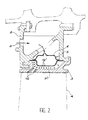
- a stator 1 of a turbomachine is equipped spacers 2 (only one of which is shown) intended to support as many 3 rings which contribute to delimit the gas flow stream of the machine in front of circular stages of moving rotor blades 4.
- the subject of the invention is an annular housing 5 composed of a cover 6 and a wall 7.
- the housing 5 is housed in a room 8 delimited by the spacer 2 and ring 3, and it cuts it between this and the outlet 9 of a gas supply circuit relatively fresh from the bottom of the combustion; the rest of the supply circuit is not shown because it is not original, but we may refer to French patent 2,416,345 cited higher for more detail.
- the integrity of the case 5 is ensured by providing the cover 6 and the wall 7 lateral edges 10 and 11 circular and likewise diameter which are joined in pairs by welds, rivets or other means; the side edges 11 of the wall 7 are also fixed to the spacer 2.
- the wall 7 is foraminated, that is to say pierced with numerous orifices 12, here substantially more long as wide thanks to their finesse and fairly large wall thickness 7.
- the cover 6 is pierced by other holes 13, less numerous than those 12 of wall 7 but whose cross section opening hours is also quite limited. They are established at the top of projections 14 obtained by pushing back the material of the cover 6 towards the outside of the case 5 and whose shape is more or less conical so that the orifices 13 communicate with the interior of the housing 5 by pavilions 15 opening towards the wall 7.
- the gas entering chamber 8 accumulates in front of the housing 5 and passes through the holes 13 then 12 to come and lick the ring 3 before being evacuated in the gas flow stream passing through holes 16 drilled through the ring 3.
- the constitution of orifices 13 calibrated with precision allows to restrict the gas flow through them without excessively reducing the flow load thanks to the flared shape of the pavilions 15.
- the projections 14 can however be oriented to favor the mean direction of gas flow in the box 5 to one region or the other of the wall 7.
- the gas flow is therefore distributed properly in the housing 5 and flows out through the orifices 12, who distribute it by directing it with precision and with the desired spatial distribution towards different portions of the ring 3.
- the density and direction of the orifices 12 can therefore vary over the wall 7.
- the conception of the invention is certainly applicable to other parts of the machine than the high pressure turbine rings, and it can also be used with charged gases to warm up the structure on which they are soufflés.
Landscapes
- Engineering & Computer Science (AREA)
- Mechanical Engineering (AREA)
- General Engineering & Computer Science (AREA)
- Turbine Rotor Nozzle Sealing (AREA)
- Motor Or Generator Cooling System (AREA)
Claims (3)
- Kühlvorrichtung für einen Turbomaschinenring (3) mit einem Speisekreis (9) für die Zufuhr von aus einem anderen Teil der Turbomaschine stammendem Kühlgas, der in einer Kammer (8) hinter dem Ring (3) mündet, wobei diese Kammer (8) zwischen dem Ring (3) und dem Kreis (9) von einem ringförmigen Verteiler geteilt wird, der eine von Öffnungen (12) durchbrochene Wand (7) äufweist, wobei der Verteiler die Form eines Gehäuses (5) hat und einen Deckel (6) besitzt, der zwischen der Wand (7) und dem Kreis (9) angeordnet und von Öffnungen (13) zur Begrenzung der Gasströmung durchbrochen ist, wobei die Öffnungen (13) des Deckels weniger zahlreich sind und einen kleineren Gesamtquerschnitt haben als die Öffnungen (12) der Wand und auf Vorsprüngen (14) angeordnet sind, die durch Austreiben des Materials des Deckels (16) zum Außenraum des Gehäuses (5) erzeugt werden und Trichter (15) bilden, die sich zu der Wand hin öffnen.
- Kühlvorrichtung nach Anspruch 1, dadurch gekennzeichnet, daß die Wand (7) eine deutlich größere Dicke hat als der Deckel (6) und daß die Öffnungen (12) der Wand mehr lang als breit sind.
- Kühlvorrichtung nach einem der Ansprüche 1 oder 2, dadurch gekennzeichnet, daß der Deckel und die Wand durch Paare von kreisförmigen Einfassungen (10, 11) gleichen Durchmessers miteinander verbunden sind.
Applications Claiming Priority (2)
| Application Number | Priority Date | Filing Date | Title |
|---|---|---|---|
| FR9709399A FR2766517B1 (fr) | 1997-07-24 | 1997-07-24 | Dispositif de ventilation d'un anneau de turbomachine |
| FR9709399 | 1997-07-24 |
Publications (2)
| Publication Number | Publication Date |
|---|---|
| EP0893577A1 EP0893577A1 (de) | 1999-01-27 |
| EP0893577B1 true EP0893577B1 (de) | 2003-08-27 |
Family
ID=9509567
Family Applications (1)
| Application Number | Title | Priority Date | Filing Date |
|---|---|---|---|
| EP98401872A Expired - Lifetime EP0893577B1 (de) | 1997-07-24 | 1998-07-23 | Kühlvorrichtung für einen Abdeckring in einer Turbomaschine |
Country Status (6)
| Country | Link |
|---|---|
| US (1) | US5964575A (de) |
| EP (1) | EP0893577B1 (de) |
| JP (1) | JP3808211B2 (de) |
| CA (1) | CA2243333C (de) |
| DE (1) | DE69817477T2 (de) |
| FR (1) | FR2766517B1 (de) |
Cited By (2)
| Publication number | Priority date | Publication date | Assignee | Title |
|---|---|---|---|---|
| EP1775426B1 (de) | 2005-10-14 | 2016-05-04 | United Technologies Corporation | Aktives Spaltkontrollsystem für Gasturbinenantriebe |
| US11035248B1 (en) | 2019-11-25 | 2021-06-15 | General Electric Company | Unitary body turbine shrouds including shot peen screens integrally formed therein and turbine systems thereof |
Families Citing this family (64)
| Publication number | Priority date | Publication date | Assignee | Title |
|---|---|---|---|---|
| US6139257A (en) * | 1998-03-23 | 2000-10-31 | General Electric Company | Shroud cooling assembly for gas turbine engine |
| FR2780443B1 (fr) * | 1998-06-25 | 2000-08-04 | Snecma | Anneau de stator de turbine haute pression d'une turbomachine |
| JP2001221065A (ja) * | 2000-02-10 | 2001-08-17 | General Electric Co <Ge> | ガスタービンシュラウドのインピンジメント冷却 |
| US6390769B1 (en) * | 2000-05-08 | 2002-05-21 | General Electric Company | Closed circuit steam cooled turbine shroud and method for steam cooling turbine shroud |
| FR2816352B1 (fr) * | 2000-11-09 | 2003-01-31 | Snecma Moteurs | Ensemble de ventilation d'un anneau de stator |
| FR2819010B1 (fr) * | 2001-01-04 | 2004-05-28 | Snecma Moteurs | Secteur d'entretoise de support d'anneau de stator de la turbine haute pression d'une turbomachine avec rattrapage de jeux |
| EP1247943A1 (de) * | 2001-04-04 | 2002-10-09 | Siemens Aktiengesellschaft | Formstück zur Bildung eines kühlbaren Turbinen-Mantelrings |
| US6508620B2 (en) | 2001-05-17 | 2003-01-21 | Pratt & Whitney Canada Corp. | Inner platform impingement cooling by supply air from outside |
| KR100444854B1 (ko) * | 2001-08-16 | 2004-08-18 | 현대자동차주식회사 | 터보차저의 터빈 블레이드 냉각 구조 |
| EP1400751A1 (de) * | 2002-09-17 | 2004-03-24 | Siemens Aktiengesellschaft | Brennkammer für eine Gasturbine |
| ITMI20022418A1 (it) * | 2002-11-15 | 2004-05-16 | Nuovo Pignone Spa | Assieme migliorato di cassa interna a dispositivo di |
| US7108479B2 (en) * | 2003-06-19 | 2006-09-19 | General Electric Company | Methods and apparatus for supplying cooling fluid to turbine nozzles |
| US6997673B2 (en) * | 2003-12-11 | 2006-02-14 | Honeywell International, Inc. | Gas turbine high temperature turbine blade outer air seal assembly |
| FR2867224B1 (fr) * | 2004-03-04 | 2006-05-19 | Snecma Moteurs | Dispositif de maintien axial de secteur d'entretoise pour anneau d'une turbine haute-pression de turbomachine |
| FR2868125B1 (fr) * | 2004-03-26 | 2006-07-21 | Snecma Moteurs Sa | Turbomachine comprenant deux sous-ensembles assembles sous contrainte axiale |
| US7118326B2 (en) * | 2004-06-17 | 2006-10-10 | Siemens Power Generation, Inc. | Cooled gas turbine vane |
| US7097418B2 (en) * | 2004-06-18 | 2006-08-29 | Pratt & Whitney Canada Corp. | Double impingement vane platform cooling |
| DE102005013797A1 (de) * | 2005-03-24 | 2006-09-28 | Alstom Technology Ltd. | Wärmestausegment |
| DE102005013796A1 (de) * | 2005-03-24 | 2006-09-28 | Alstom Technology Ltd. | Wärmestausegment |
| US20070009349A1 (en) * | 2005-07-11 | 2007-01-11 | General Electric Company | Impingement box for gas turbine shroud |
| US20070249823A1 (en) * | 2006-04-20 | 2007-10-25 | Chemagis Ltd. | Process for preparing gemcitabine and associated intermediates |
| US7607885B2 (en) * | 2006-07-31 | 2009-10-27 | General Electric Company | Methods and apparatus for operating gas turbine engines |
| FR2907841B1 (fr) * | 2006-10-30 | 2011-04-15 | Snecma | Secteur d'anneau de turbine de turbomachine |
| US7665962B1 (en) | 2007-01-26 | 2010-02-23 | Florida Turbine Technologies, Inc. | Segmented ring for an industrial gas turbine |
| US7597533B1 (en) | 2007-01-26 | 2009-10-06 | Florida Turbine Technologies, Inc. | BOAS with multi-metering diffusion cooling |
| US8439629B2 (en) * | 2007-03-01 | 2013-05-14 | United Technologies Corporation | Blade outer air seal |
| US8439639B2 (en) * | 2008-02-24 | 2013-05-14 | United Technologies Corporation | Filter system for blade outer air seal |
| US8100633B2 (en) * | 2008-03-11 | 2012-01-24 | United Technologies Corp. | Cooling air manifold splash plates and gas turbines engine systems involving such splash plates |
| US8092146B2 (en) * | 2009-03-26 | 2012-01-10 | Pratt & Whitney Canada Corp. | Active tip clearance control arrangement for gas turbine engine |
| FR2955891B1 (fr) * | 2010-02-02 | 2012-11-16 | Snecma | Secteur d'anneau de turbine de turbomachine |
| FR2972483B1 (fr) * | 2011-03-07 | 2013-04-19 | Snecma | Carter de turbine comportant des moyens de fixation de secteurs d'anneau |
| US8998565B2 (en) * | 2011-04-18 | 2015-04-07 | General Electric Company | Apparatus to seal with a turbine blade stage in a gas turbine |
| US9080458B2 (en) | 2011-08-23 | 2015-07-14 | United Technologies Corporation | Blade outer air seal with multi impingement plate assembly |
| US8840370B2 (en) | 2011-11-04 | 2014-09-23 | General Electric Company | Bucket assembly for turbine system |
| US9726043B2 (en) | 2011-12-15 | 2017-08-08 | General Electric Company | Mounting apparatus for low-ductility turbine shroud |
| US20130283814A1 (en) * | 2012-04-25 | 2013-10-31 | General Electric Company | Turbine cooling system |
| US9127549B2 (en) * | 2012-04-26 | 2015-09-08 | General Electric Company | Turbine shroud cooling assembly for a gas turbine system |
| DE102012016493A1 (de) * | 2012-08-21 | 2014-02-27 | Rolls-Royce Deutschland Ltd & Co Kg | Gasturbinenbrennkammer mit prallgekühlten Bolzen der Brennkammerschindeln |
| CN103775139B (zh) * | 2012-10-26 | 2015-09-23 | 中航商用航空发动机有限责任公司 | 涡轮发动机的间隙控制系统及涡轮发动机的间隙控制方法 |
| EP2728255A1 (de) * | 2012-10-31 | 2014-05-07 | Alstom Technology Ltd | Heißgas-Segmentanordnung |
| CN103161520A (zh) * | 2013-03-01 | 2013-06-19 | 哈尔滨汽轮机厂有限责任公司 | 一种中低热值燃机第一级涡轮护环装置及其拆卸方法 |
| FR3002971B1 (fr) * | 2013-03-06 | 2015-04-17 | Snecma | Dispositif de ventilation d'un carter de stator d'une turbomachine, comprenant un ajustement sur des circonferences |
| FR3002972B1 (fr) * | 2013-03-06 | 2015-04-17 | Snecma | Dispositif de ventilation d'un carter de stator d'une turbomachine comprenant un ajustement en direction axiale |
| US20140271154A1 (en) * | 2013-03-14 | 2014-09-18 | General Electric Company | Casing for turbine engine having a cooling unit |
| CA2912428C (en) | 2013-05-17 | 2018-03-13 | General Electric Company | Cmc shroud support system of a gas turbine |
| EP3080403B1 (de) | 2013-12-12 | 2019-05-01 | General Electric Company | Trägersystem für cmc-mantel |
| WO2015138027A2 (en) * | 2013-12-17 | 2015-09-17 | United Technologies Corporation | Meter plate for blade outer air seal |
| WO2016025054A2 (en) * | 2014-05-29 | 2016-02-18 | General Electric Company | Engine components with cooling features |
| CA2951638A1 (en) | 2014-06-12 | 2015-12-17 | General Electric Company | Shroud hanger assembly |
| CA2951425C (en) | 2014-06-12 | 2019-12-24 | General Electric Company | Shroud hanger assembly |
| CN106460543B (zh) | 2014-06-12 | 2018-12-21 | 通用电气公司 | 多件式护罩悬挂器组件 |
| EP3183431B1 (de) * | 2014-08-22 | 2018-10-10 | Siemens Aktiengesellschaft | Deckbandkühlsystem für deckbänder neben in schaufeln in gasturbinenmotoren |
| US9874104B2 (en) | 2015-02-27 | 2018-01-23 | General Electric Company | Method and system for a ceramic matrix composite shroud hanger assembly |
| US10337346B2 (en) * | 2016-03-16 | 2019-07-02 | United Technologies Corporation | Blade outer air seal with flow guide manifold |
| US11193386B2 (en) * | 2016-05-18 | 2021-12-07 | Raytheon Technologies Corporation | Shaped cooling passages for turbine blade outer air seal |
| US10626751B2 (en) * | 2017-05-30 | 2020-04-21 | United Technologies Corporation | Turbine cooling air metering arrangement |
| US10612406B2 (en) * | 2018-04-19 | 2020-04-07 | United Technologies Corporation | Seal assembly with shield for gas turbine engines |
| FR3082872B1 (fr) * | 2018-06-25 | 2021-06-04 | Safran Aircraft Engines | Dispositif de refroidissement d'un carter de turbomachine |
| US10914192B2 (en) * | 2018-09-25 | 2021-02-09 | Raytheon Technologies Corporation | Impingement cooling for gas turbine engine component |
| US10914186B2 (en) * | 2018-12-05 | 2021-02-09 | Raytheon Technologies Corporation | BOAS control structure with center support hook |
| US10830050B2 (en) * | 2019-01-31 | 2020-11-10 | General Electric Company | Unitary body turbine shrouds including structural breakdown and collapsible features |
| US11761343B2 (en) * | 2019-03-13 | 2023-09-19 | Rtx Corporation | BOAS carrier with dovetail attachments |
| US11248482B2 (en) * | 2019-07-19 | 2022-02-15 | Raytheon Technologies Corporation | CMC BOAS arrangement |
| FR3108367B1 (fr) * | 2020-03-20 | 2023-07-21 | Safran Aircraft Engines | Ensemble de turbine et turbomachine munie d’un tel ensemble |
Family Cites Families (7)
| Publication number | Priority date | Publication date | Assignee | Title |
|---|---|---|---|---|
| US3703808A (en) * | 1970-12-18 | 1972-11-28 | Gen Electric | Turbine blade tip cooling air expander |
| US3825364A (en) * | 1972-06-09 | 1974-07-23 | Gen Electric | Porous abradable turbine shroud |
| US3844343A (en) * | 1973-02-02 | 1974-10-29 | Gen Electric | Impingement-convective cooling system |
| US4157232A (en) * | 1977-10-31 | 1979-06-05 | General Electric Company | Turbine shroud support |
| GB2116639B (en) * | 1982-03-05 | 1985-11-20 | Rolls Royce | Turbine shroud segments and turbine shroud assembly |
| US5048288A (en) * | 1988-12-20 | 1991-09-17 | United Technologies Corporation | Combined turbine stator cooling and turbine tip clearance control |
| US5165847A (en) * | 1991-05-20 | 1992-11-24 | General Electric Company | Tapered enlargement metering inlet channel for a shroud cooling assembly of gas turbine engines |
-
1997
- 1997-07-24 FR FR9709399A patent/FR2766517B1/fr not_active Expired - Fee Related
-
1998
- 1998-07-15 CA CA002243333A patent/CA2243333C/en not_active Expired - Lifetime
- 1998-07-15 US US09/115,695 patent/US5964575A/en not_active Expired - Lifetime
- 1998-07-21 JP JP20483498A patent/JP3808211B2/ja not_active Expired - Lifetime
- 1998-07-23 DE DE69817477T patent/DE69817477T2/de not_active Expired - Lifetime
- 1998-07-23 EP EP98401872A patent/EP0893577B1/de not_active Expired - Lifetime
Cited By (2)
| Publication number | Priority date | Publication date | Assignee | Title |
|---|---|---|---|---|
| EP1775426B1 (de) | 2005-10-14 | 2016-05-04 | United Technologies Corporation | Aktives Spaltkontrollsystem für Gasturbinenantriebe |
| US11035248B1 (en) | 2019-11-25 | 2021-06-15 | General Electric Company | Unitary body turbine shrouds including shot peen screens integrally formed therein and turbine systems thereof |
Also Published As
| Publication number | Publication date |
|---|---|
| FR2766517A1 (fr) | 1999-01-29 |
| EP0893577A1 (de) | 1999-01-27 |
| FR2766517B1 (fr) | 1999-09-03 |
| JP3808211B2 (ja) | 2006-08-09 |
| DE69817477T2 (de) | 2004-06-09 |
| JPH1181907A (ja) | 1999-03-26 |
| CA2243333A1 (en) | 1999-01-24 |
| DE69817477D1 (de) | 2003-10-02 |
| US5964575A (en) | 1999-10-12 |
| CA2243333C (en) | 2007-11-06 |
Similar Documents
| Publication | Publication Date | Title |
|---|---|---|
| EP0893577B1 (de) | Kühlvorrichtung für einen Abdeckring in einer Turbomaschine | |
| EP1134360B1 (de) | Verstellvorrichtung für den Durchmesser des Stators eines Gasturbinenwerks | |
| EP1164253B1 (de) | Kühlungssystem für die Abdeckplatten von Rotorschaufelpaaren | |
| FR2502242A1 (fr) | Embout rapporte pour aube de rotor | |
| EP2406463B1 (de) | Turbinenschaufel mit entstaubungsloch am schaufelfuss | |
| FR2720860A1 (fr) | Batterie fonctionnant à température élevée. | |
| EP0785338B1 (de) | Kühleinrichtung für eine Turbinenscheibe | |
| FR2742804A1 (fr) | Rotor deshuileur pour enceinte de lubrification | |
| EP0017517B1 (de) | Leitvorrichtung zur Mischung trockener und nasser paralleler Kühlluftströme | |
| FR2929323A1 (fr) | Procede de refroidissement d'une piece de turbine et piece de turbine correspondante | |
| WO2002086291A1 (fr) | Aube pour turbine comportant un deflecteur d'air de refroidissement | |
| WO2003018962A1 (fr) | Carter de stator de turbomachine | |
| FR2750451A1 (fr) | Dispositif de soufflage de gaz de reglage de jeux dans une turbomachine | |
| EP1586743A1 (de) | Turbinen-Mantelring | |
| CA1037443A (fr) | Dispositif d'aspiration et de depoussierage humide | |
| FR3125844A1 (fr) | Turbomachine comportant un cône de sortie intégrant des composants refroidis par circulation d’un flux de refroidissement | |
| FR2707698A1 (fr) | Turbomachine munie d'un moyen de soufflage d'air sur un élément de rotor. | |
| FR2629009A1 (fr) | Plaque perforee pour granulation de cordons de matiere plastique en milieu aqueux | |
| FR2630162A1 (fr) | Systeme d'antigivrage de cone d'entree pour turbomoteurs a gaz | |
| FR2723144A1 (fr) | Distributeur de turbine | |
| EP1766219A1 (de) | Kühlvorrichtung für die hauptdüse eines turbinen-luftstrahl-triebwerks mit doppeldurchfluss | |
| EP3959138A1 (de) | Gondellufteinlass und gondel mit einem solchen lufteinlass | |
| FR2516597A1 (fr) | Dispositif annulaire de joint d'usure et d'etancheite refroidi par l'air pour aubage de roue de turbine a gaz ou de compresseur | |
| EP1819861B1 (de) | Vorrichtung zur herstellung von faserfilzen | |
| EP1867928B1 (de) | Dampfbackofen |
Legal Events
| Date | Code | Title | Description |
|---|---|---|---|
| PUAI | Public reference made under article 153(3) epc to a published international application that has entered the european phase |
Free format text: ORIGINAL CODE: 0009012 |
|
| 17P | Request for examination filed |
Effective date: 19980810 |
|
| AK | Designated contracting states |
Kind code of ref document: A1 Designated state(s): DE FR GB |
|
| AX | Request for extension of the european patent |
Free format text: AL;LT;LV;MK;RO;SI |
|
| AKX | Designation fees paid |
Free format text: DE FR GB |
|
| GRAH | Despatch of communication of intention to grant a patent |
Free format text: ORIGINAL CODE: EPIDOS IGRA |
|
| GRAH | Despatch of communication of intention to grant a patent |
Free format text: ORIGINAL CODE: EPIDOS IGRA |
|
| RAP1 | Party data changed (applicant data changed or rights of an application transferred) |
Owner name: SNECMA MOTEURS |
|
| GRAA | (expected) grant |
Free format text: ORIGINAL CODE: 0009210 |
|
| AK | Designated contracting states |
Designated state(s): DE FR GB |
|
| REG | Reference to a national code |
Ref country code: GB Ref legal event code: FG4D Free format text: NOT ENGLISH |
|
| REF | Corresponds to: |
Ref document number: 69817477 Country of ref document: DE Date of ref document: 20031002 Kind code of ref document: P |
|
| GBT | Gb: translation of ep patent filed (gb section 77(6)(a)/1977) |
Effective date: 20031006 |
|
| PLBE | No opposition filed within time limit |
Free format text: ORIGINAL CODE: 0009261 |
|
| STAA | Information on the status of an ep patent application or granted ep patent |
Free format text: STATUS: NO OPPOSITION FILED WITHIN TIME LIMIT |
|
| 26N | No opposition filed |
Effective date: 20040528 |
|
| REG | Reference to a national code |
Ref country code: FR Ref legal event code: CD |
|
| REG | Reference to a national code |
Ref country code: FR Ref legal event code: PLFP Year of fee payment: 18 |
|
| REG | Reference to a national code |
Ref country code: FR Ref legal event code: PLFP Year of fee payment: 19 |
|
| REG | Reference to a national code |
Ref country code: FR Ref legal event code: PLFP Year of fee payment: 20 |
|
| PGFP | Annual fee paid to national office [announced via postgrant information from national office to epo] |
Ref country code: FR Payment date: 20170427 Year of fee payment: 20 Ref country code: GB Payment date: 20170620 Year of fee payment: 20 |
|
| PGFP | Annual fee paid to national office [announced via postgrant information from national office to epo] |
Ref country code: DE Payment date: 20170620 Year of fee payment: 20 |
|
| REG | Reference to a national code |
Ref country code: FR Ref legal event code: CD Owner name: SAFRAN AIRCRAFT ENGINES Effective date: 20170719 |
|
| REG | Reference to a national code |
Ref country code: DE Ref legal event code: R071 Ref document number: 69817477 Country of ref document: DE |
|
| REG | Reference to a national code |
Ref country code: GB Ref legal event code: PE20 Expiry date: 20180722 |
|
| PG25 | Lapsed in a contracting state [announced via postgrant information from national office to epo] |
Ref country code: GB Free format text: LAPSE BECAUSE OF EXPIRATION OF PROTECTION Effective date: 20180722 |