EP0893587A2 - Générateur entrainé par un moteur à combustion interne - Google Patents
Générateur entrainé par un moteur à combustion interne Download PDFInfo
- Publication number
- EP0893587A2 EP0893587A2 EP98305832A EP98305832A EP0893587A2 EP 0893587 A2 EP0893587 A2 EP 0893587A2 EP 98305832 A EP98305832 A EP 98305832A EP 98305832 A EP98305832 A EP 98305832A EP 0893587 A2 EP0893587 A2 EP 0893587A2
- Authority
- EP
- European Patent Office
- Prior art keywords
- compartment
- engine
- duct
- frame member
- generator
- Prior art date
- Legal status (The legal status is an assumption and is not a legal conclusion. Google has not performed a legal analysis and makes no representation as to the accuracy of the status listed.)
- Granted
Links
Images


Classifications
-
- F—MECHANICAL ENGINEERING; LIGHTING; HEATING; WEAPONS; BLASTING
- F02—COMBUSTION ENGINES; HOT-GAS OR COMBUSTION-PRODUCT ENGINE PLANTS
- F02B—INTERNAL-COMBUSTION PISTON ENGINES; COMBUSTION ENGINES IN GENERAL
- F02B77/00—Component parts, details or accessories, not otherwise provided for
- F02B77/11—Thermal or acoustic insulation
- F02B77/13—Acoustic insulation
-
- F—MECHANICAL ENGINEERING; LIGHTING; HEATING; WEAPONS; BLASTING
- F02—COMBUSTION ENGINES; HOT-GAS OR COMBUSTION-PRODUCT ENGINE PLANTS
- F02B—INTERNAL-COMBUSTION PISTON ENGINES; COMBUSTION ENGINES IN GENERAL
- F02B63/00—Adaptations of engines for driving pumps, hand-held tools or electric generators; Portable combinations of engines with engine-driven devices
- F02B63/04—Adaptations of engines for driving pumps, hand-held tools or electric generators; Portable combinations of engines with engine-driven devices for electric generators
-
- F—MECHANICAL ENGINEERING; LIGHTING; HEATING; WEAPONS; BLASTING
- F02—COMBUSTION ENGINES; HOT-GAS OR COMBUSTION-PRODUCT ENGINE PLANTS
- F02B—INTERNAL-COMBUSTION PISTON ENGINES; COMBUSTION ENGINES IN GENERAL
- F02B75/00—Other engines
- F02B75/16—Engines characterised by number of cylinders, e.g. single-cylinder engines
-
- F—MECHANICAL ENGINEERING; LIGHTING; HEATING; WEAPONS; BLASTING
- F02—COMBUSTION ENGINES; HOT-GAS OR COMBUSTION-PRODUCT ENGINE PLANTS
- F02B—INTERNAL-COMBUSTION PISTON ENGINES; COMBUSTION ENGINES IN GENERAL
- F02B63/00—Adaptations of engines for driving pumps, hand-held tools or electric generators; Portable combinations of engines with engine-driven devices
- F02B63/04—Adaptations of engines for driving pumps, hand-held tools or electric generators; Portable combinations of engines with engine-driven devices for electric generators
- F02B63/044—Adaptations of engines for driving pumps, hand-held tools or electric generators; Portable combinations of engines with engine-driven devices for electric generators the engine-generator unit being placed on a frame or in an housing
- F02B2063/045—Frames for generator-engine sets
-
- F—MECHANICAL ENGINEERING; LIGHTING; HEATING; WEAPONS; BLASTING
- F02—COMBUSTION ENGINES; HOT-GAS OR COMBUSTION-PRODUCT ENGINE PLANTS
- F02B—INTERNAL-COMBUSTION PISTON ENGINES; COMBUSTION ENGINES IN GENERAL
- F02B63/00—Adaptations of engines for driving pumps, hand-held tools or electric generators; Portable combinations of engines with engine-driven devices
- F02B63/04—Adaptations of engines for driving pumps, hand-held tools or electric generators; Portable combinations of engines with engine-driven devices for electric generators
- F02B63/044—Adaptations of engines for driving pumps, hand-held tools or electric generators; Portable combinations of engines with engine-driven devices for electric generators the engine-generator unit being placed on a frame or in an housing
- F02B63/048—Portable engine-generator combinations
Definitions
- the present invention relates to an engine-operated generator covered by a soundproof case in its entirety.
- the engine-operated generator in which an engine and a generator driven by the engine are integrated is used at a construction work site generally. And in consideration of influences to the surroundings when it is operated in a city area especially at night, an engine-operated generator covered by a soundproof case in its entirety has been used widely in order to restrain operation noise as low as possible.
- openings for suctioning or discharging air are made few in number and small in size to achieve necessary silence during operation. But on the one hand, it is necessary to devote great care to cooling interior of the soundproof case because the area of the opening is small.
- an interior of a soundproof case is partitioned into a suction compartment for housing an air-cleaner and a carburetor, a first heat source compartment for housing an engine and a muffler, a second heat source compartment for housing a generator and a silencer compartment to improve sound interrupting effect and cooling effect.
- the present invention has been accomplished in view of the foregoing and one object of the invention is to provide a compact engine-operated generator in which instruments in a soundproof case are arranged efficiently from the viewpoint of measures for sound and heat.
- the present invention provides an engine-operated generator having an engine and a generator driven by the engine arranged in a direction of a rotary shaft and accommodated in a soundproof case, comprising a plate-like front frame member and a plate-like rear frame member partitioning an interior of the soundproof case into a front compartment, a center compartment and a rear compartment; a through hole formed in the rear frame member; a duct provided in the through hole swelling out toward the center compartment side and the rear compartment side; a generator, an engine and a muffler accommodated in the duct; a fuel tank and suction system instruments disposed outside of the duct within the center compartment; and electric instruments disposed within the front compartment.
- the engine-operated generator has a simple construction
- the generator, the engine and the muffler, which are sources of operation noise and heat are accommodated in the duct to be separated by the duct and the soundproof case doubly from the exterior, and heat generating instruments, fuel system instruments and electric instruments are disposed each gathered separately and isolated from each other in such manner that on the outside of the duct not influenced by the high temperature heat, the fuel tank and the suction system instruments are accommodated in the center compartment and the electric instruments in the front compartment. Therefore, each instrument can be disposed efficiently from the viewpoint of measures for sound and heat and the whole apparatus can be made compact easily.
- the heat source instruments such as the generator, the engine and the muffler are concentrated in the same duct, cooling of the instruments can be carried out efficiently by ventilating the duct.
- the noise sources such as the engine and the muffler are covered doubly by the duct and the soundproof case, a high sound interrupting effect can be obtained.
- the engine-operated generator may have a suction hole formed in an outer wall of the front compartment, a communication open hole formed in the front frame member for connecting the front compartment with the center compartment, a suction opening of the duct opening into the center compartment, and a discharge hole of the duct opening to an exterior of the rear compartment. Outside air introduced in the front compartment through the suction hole enters the center compartment through the communication open hole, is inhaled in the duct through the suction opening of the duct, cools the generator, the engine and the muffler in order, and then is discharged through the discharge hole to the exterior.
- the front compartment having the outer wall formed with the suction hole acts as a labyrinth duct for introducing outside air which restrains leakage of suction noise occurring in the center compartment in addition to cooling the electric instruments.
- the outside air introduced in the front compartment is inhaled in the center compartment through the communication open hole, then in the duct through the suction opening thereof and cools firstly the generator of relatively low temperature, then the engine and the muffler of higher temperature in turn to be discharged through the discharge hole.
- an efficient cooling can be carried out by the simple ventilation construction.
- a pair of right and left reinforcing members may be laid between upper portions of the front frame member and the rear frame member, and a fuel tank may be placed fixedly on the reinforcing members.
- the fuel tank is disposed within the center compartment together with suction system instruments so that fuel system parts of the engine can be concentrated in the lump.
- a large-sized fuel tank can be disposed in an upper part of the center compartment compactly.
- a control circuit unit may be disposed in an air passage extending from the suction hole formed in the outer wall of the front compartment to the communication open hole of the front frame member.
- the control circuit unit having to be restrained from temperature rise can be cooled efficiently in the front compartment where the outside air is introduced firstly, separately from other instruments.
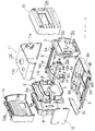
- the engine-operated generator 1 according to the preferred embodiment is covered with a soundproof case 2 in its entirety to form a cube as shown in Fig. 1.
- Fig. 2 is an exploded perspective view of the soundproof case 2 and other inner frame members.
- An under frame member 3 is formed in a shape of a flat saucer and has a front side wall 3a, a right side wall 3b and a rear side wall 3c.
- the front and right side walls 3a, 3b are provided with suction holes 4a, 4b.
- the rear side wall 3c is detachable.
- On the inner side of the under frame member 3 are laid a pair of front and rear supporting members 3p, 3q extending in the right-left direction in parallel with each other.
- under frame member 3 On the under frame member 3 are erected substantially rectangular front and rear frame members 5, 6 facing to each other at a predetermined interval.
- a rectangular panel portion of the front frame member 5 has a rectangular open hole 5b elongated in the right-left direction at an upper part and a communication open hole 5c formed in a shape of a partly swelled circle at a lower part.
- the rear frame member 6 is split into upper and lower parts and a large rectangular central through hole 7a is formed when the upper and lower parts are joined. From the through hole 7a is projected forward a duct 7 formed integrally with the rear frame member 6. Upper edge portions of the rear frame member 6 are bent forward to form flanges 6a. The front portion of the duct 7 is shaped in a rectangular pipe opening to the front.
- a duct 8 made of glass wool is disposed behind the rear frame member 6.
- the duct 8 swells out rearward communicating with the duct 7 through the through hole 7a.
- the duct 8 is shaped in a substantially rectangular box opening toward the front and bottom and having a discharge hole 8a at an upper side wall.
- a pair of right and left reinforcing rails 9, 9 are provided directed in front-rear direction and penetrating upper corners of the frame members 5, 6.
- a center cover 11 shaped as a halved square pipe is placed along outer peripheral edges of the front and rear frame members 5, 6 for covering the space between the frame members 5, 6 to partition the space from the exterior.
- the center cover 11 is formed in a shape of a half of a square pipe by bending a plate and has a left side wall 11a, an upper wall 11b and a right upper side wall 11c.
- the right under side of the center cover 11 is covered by an opening and closing separate lid member 12 to partition a center compartment 22 (Fig. 3) therein.
- a center compartment 22 Fig. 3
- a circular hole lid through which a refueling mouth 55b of a fuel tank 55 projects (Fig. 4).
- a front of the front frame member 5 is covered by a front cover 13 shaped in a generally rectangular box to partition a front compartment 21.
- An under part of an outer wall of the front compartment is formed by the aforementioned front and rear side walls 3a, 3b of the under frame member 3.
- a rear of the rear frame member 6 is covered by a rear cover 14 shaped in a generally rectangular box to partition a rear compartment 23.
- the rear cover 14 Along the inner surface of the rear cover 14 extends the aforementioned glass wool duct 8 as a liner. Therefore, the rear compartment 23 is formed inside of the duct 8.
- a central portion of a front wall of the front cover 13 is recessed and there is formed a rectangular opening 13a for a control panel 62.
- a rectangular opening 14a In an upper wall of the rear cover 14 is formed a rectangular opening 14a corresponding to the discharge hole 8a provided on the aforementioned duct 8.
- the soundproof case 2 constituting an outer wall of the engine-operated generator 1 has six faces formed by the under frame member 3, the center cover 11, the lid member 12, the front cover 13 and the rear cover 14. And inner space of the soundproof case 2 is partitioned into the front compartment 21, the center compartment 22 and the rear compartment 23 by the front frame member 5 and the rear frame member 6.
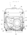
- a fan cover 16 which serves as a duct too, continuously to the rectangular-pipe-like section of the duct 7 swelling out into the center compartment 22 from the rear frame member 6.
- the fan cover 16 is formed about cylindrical to cover a generator 35 and a centrifugal fan 40 and has a suction opening 16a which is a circular opening at the front end.
- a plurality of projections 16b having predetermined lengths.
- the fan cover 16 has a flange 16c projecting radially outward at the opening rear end and a rectangular frame member 17 is attached to the flange 16c from the rear.
- the rectangular frame member 17 is surrounded by a seal rubber 18 along the rectangular outer peripheral edge and fitted in the rectangular-pipe-like section of the duct 7 being sealed by the seal rubber 18.
- the fan cover 16 is connected with the duct 7 of the rear frame member 6 through the rectangular frame member 17 and the duct 7 is connected with the duct 8 which swells out rearward from the rear frame member 6 to form the rear compartment 23.
- a duct space formed by the fan cover 16, the duct 7 and the duct 8 occupies the rear compartment 23 and a part of the center compartment 22.
- the duct space has an upper stream side suction opening 16a opening into the center compartment 22 and a lower stream side discharge opening 8a provided in the upper side wall of the duct 8.
- the discharge opening 8a faces the rectangular opening 14a of the rear cover 14 and opens to the exterior of the soundproof case 2.
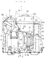
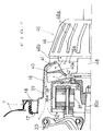
- the engine 30 is accommodated in the ducts 7, 8 at the rear of the soundproof case 2 as shown in Fig. 4, and supported by a pair of right and left vibrationproof mount member 31 fixed to the supporting member 3q on the under frame member 3 (Figs. 4 and 6).
- the engine 30 has a crankcase 30a positioned biased to the left side, a cylinder 30b projecting inclined to the right direction somewhat upwardly and a crankshaft 30c directed in front-rear direction horizontally and projecting forward.
- a large cylindrical muffler 32 is disposed directed in right-left direction.
- the muffler 32 is supported by the engine by means of a bracket 33 and an exhaust pipe 34 extending upward from the cylinder 30b is connected with the muffler 32.
- a tail pipe 32a extends around the muffler 32 from a right side wall to a rear face thereof, and exhaust opening of the tail pipe is positioned in the vicinity of the discharge opening 8a.
- the generator 35 is connected to the crankshaft 30c projecting forward from the crankcase 30a.
- the generator 35 is an outer-rotor type multipolar generator having an outer-rotor 36 shaped in a bottomed cylinder fixed to the crankshaft 30c integrally.
- a plurality of magnets 36a are stuck circumferentially on an inner surface of a peripheral wall of the rotor 36 so as to rotate together with the crankshaft 30c.
- the outer-rotor 36 serves as a flywheel of the engine, too.
- the outer-rotor 36 has a bottom wall at the front and opens rearward.
- a stator core having a plurality of radial yokes and generating coils wound on the yokes is fixed to the crankcase 30a.
- the bottom wall of the outer-rotor 36 is formed with a plurality of ventilating holes 36b and the centrifugal fan 40 is fixed to the bottom wall of the outer-rotor 36 from the front.
- the centrifugal fan 40 is a two faces fan having fan blades 41, 42 on both front and rear faces of a disk-like base plate 40a.
- the fan cover 16 covers the generator 35 and the centrifugal fan 40 with the suction opening 16a at the front end opposed to the centrifugal fan 40.
- the rear end of the fan cover 16 is fixed to the crankcase 30a of the engine 30 together with the rectangular frame member 17.
- a recoil starter 45 is provided opposite to the suction opening 16a.
- a predetermined space is left between the recoil starter 45 and the fan cover 16 by the projection 16b on the end surface surrounding the suction opening 16a of the fan cover 16.
- a boss section 46b of a starter case 46 of the recoil starter 45 is fixed to the fan cover 16 to be supported integrally.
- the recoil starter 45 has a ratchet wheel 47 provided on a rotary shaft which is coaxial with the crankshaft 30c so as to be projected rearward.
- a ratchet 48 opposing to the ratchet wheel 47 is attached to a central part of the centrifugal fan 40
- the ratchet wheel 47 is driven through a gear train 47a by a starter lever and also driven by a starter motor 49 provided at a left end of the starter case 46.
- the ratchet wheel 47 When the ratchet wheel 47 usually separated from the ratchet 48 is driven by the starter motor 49 for example, the ratchet wheel 47 projects rearward to engage with the ratchet 48 and the crankshaft 30c is rotated forcibly through the ratchet 48 and the outer-rotor 36 to start the engine 30.
- the starter case 46 of the recoil starter 45 has a conical wall in which a plurality of slits 46a are formed arranged circumferentially. Cooling air is introduced into the suction opening 16a of the fan cover 16 through the space between the end face of the fan cover 16 and the starter case 46 and further through the slits 46a.
- the recoil starter 45 is positioned in the center compartment 22 and supported by a pair of right and left vibrationproof mount members 50 fixed to the supporting member 3p on the under frame member 3 (Figs. 4, 5).
- the engine 30 and the recoil starter 45 are connected integrally by the fan cover 16 to constitute a vibratory unit.
- the engine 30 in the rear is supported by the vibrationproof mount member 31 and the recoil starter 45 in the front is supported by the vibrationproof mount member 50, so that the vibratory unit can be supported efficiently at positions near front and rear both end portions thereof.
- the fuel tank 55 is disposed in a space above the fan cover 16, the recoil starter 45, the carburetor 52 and the air-cleaner 53 in the center compartment 22.
- the fuel tank 55 is supported on the right and left reinforcing rails 9 laid between the front frame member 5 and the rear frame member 6 by means of a flange 55a fixed to the rails 9 by bolts 57 with vibrationproof rubbers 56 inserted.
- a part of the fuel tank 55 is extruded into the front compartment 21 through the upper open hole 5b of the front frame member 5.
- the refueling mouth 55b of the fuel tank 55 is projected upward through the circular hole lid of the center cover 11 and a fuel cap 58 is screwed on an upper end of the refueling mouth 55b.
- the fuel tank 55 is disposed in a space outside of the fan cover 16 and the duct 7 within the center compartment together with suction system instruments such as the carburetor 52 and the air-cleaner 53, and fuel system parts of the engine 30 are concentrated in the lump.
- suction system instruments such as the carburetor 52 and the air-cleaner 53, and fuel system parts of the engine 30 are concentrated in the lump.
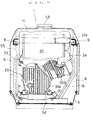
- an inverter device 60 and a battery 61 is disposed right and left on the under frame member 3 and above them is provided a control panel 62 facing the front rectangular opening 13a of the front cover 13. Namely, electric instruments are concentrated in the front compartment 21.
- the inverter device 60 converts output of the multipolar generator 35 into alternating current of a predetermined frequency.
- the inverter device 60 is disposed on the right side of the front compartment 21 near the suction holes 4a, 4b to be cooled by sucked outer air at the outset.
- the engine-operated generator 1 having the soundproof case 2 is constructed in such a manner that the generator 35, the engine 30 and the muffler 32 are arranged in this order and accommodated in the ducts 7, 8 and the fan cover 16.
- the suction opening 16a of the fan cover 16 opens into the center compartment 22 and the centrifugal fan 40 is provided inside of the suction opening 16a, so that by rotation of the centrifugal fan 40, air is introduced into the center compartment 22 through the front compartment 21 from exterior of the soundproof case 2 and inhaled in the fan cover 16 through the slits 46b in the starter case 46 of the recoil starter 45, the space between the fan cover 16 and the starter case 46, and the suction opening 16a (streams of the air are shown by arrows of dotted line in Figs. 4 and 7).
- air inhaled in the fan cover 16 through the suction opening 16a by the fan blade 41 on the front face of the centrifugal fan 40 flows along the inner peripheral surface of the fan cover 16 and the outside of the outer-rotor 36 of the generator 35 toward the engine 30 to cool the engine.
- a part of the air flowing toward the engine 30 is directed to the inside of the outer-rotor 36 through a space between the generator 35 and the engine 30 by action of the fan blade 42 on the rear face of the centrifugal fan 40 to cool the generating coil and returns to the centrifugal fan 42 through the ventilating holes 36b in the bottom wall of the outer-rotor 36 for recirculation.
- the air introduced in the engine 30 including the above-mentioned recirculated air cools the engine and then flows upward guided by the ducts 7, 8 to cool the muffler 32 (Fig. 4). After cooling the muffler 32, the air is discharged to the exterior through the discharge opening 8a of the soundproof case 2 positioned above the muffler facing the exterior.
- the center compartment 22 communicates with the front compartment 21 through the communication open hole 5c of the front frame member 5, air introduced from the exterior through the suction holes 4a, 4b into the front compartment 21 is inhaled in the center compartment 22.
- the front compartment 21 acts as a labyrinth duct for introducing exterior air which restrains leakage of suction noise occurring in the center compartment 22.
- the inverter device 60 is positioned in the course of the suction air stream from the suction holes 4a, 4b to be cooled effectively.
- the generator 35, the engine 30 and the muffler 32 which are heat sources are covered by the fan cover 16 and the ducts 7, 8 to be isolated from other instruments, and the air inhaled in the fan cover 16 by the centrifugal fan 40 through the suction opening 16a opening into the center compartment 22 cools firstly the generator 35 of relatively low temperature and then the engine 30 and the muffler 32 of higher temperature and discharged to the exterior through the discharge opening 8a. Therefore, an efficient cooling can be carried out.
- the centrifugal fan 40 is attached to the outer-rotor 36 of the generator 30, the cooling fan 40 of large capacity can be furnished and a high fan supporting strength can be obtained.
- the muffler 32 is disposed above the engine 30 in such a manner that the hotter instrument is positioned at the higher position and the discharge opening 8a is provided above the muffler 32, a reasonable cooling air stream can be generated for efficient cooling.
- the engine-operated generator 1 has a simple construction that the interior of the soundproof case 2 is partitioned into three compartments by the front frame member 5 and the rear frame member 6, and the ducts 7, 8 are provided in the through hole 7a of the rear frame member 6.
- the generator 35, the engine 30 and the muffler 32 which are sources of operation noise and heat, are accommodated in the ducts 7, 8 and the fan cover 16 being separated doubly from the exterior.
- Heat generating instruments, fuel system instruments and electric instruments are disposed each gathered separately and isolated from each other in such manner that on the outside of the duct 7 and the fan cover 16 not influenced by the high temperature heat, suction system instruments as the carburetor 52 and the air-cleaner 53 and fuel system instruments as the fuel tank 55 are accommodated in the center compartment, and electric instruments as the inverter device 60, the control panel 62 and the battery 61 in the front compartment. Therefore, each instrument can be disposed efficiently from the viewpoint of measures for sound and heat and the whole apparatus can be made compact easily.
Landscapes
- Engineering & Computer Science (AREA)
- Chemical & Material Sciences (AREA)
- Combustion & Propulsion (AREA)
- Mechanical Engineering (AREA)
- General Engineering & Computer Science (AREA)
- Physics & Mathematics (AREA)
- Acoustics & Sound (AREA)
- Motor Or Generator Frames (AREA)
- Connection Of Motors, Electrical Generators, Mechanical Devices, And The Like (AREA)
- Motor Or Generator Cooling System (AREA)
Applications Claiming Priority (3)
| Application Number | Priority Date | Filing Date | Title |
|---|---|---|---|
| JP19866997 | 1997-07-24 | ||
| JP19866997A JP3800372B2 (ja) | 1997-07-24 | 1997-07-24 | エンジン発電機 |
| JP198669/97 | 1997-07-24 |
Publications (3)
| Publication Number | Publication Date |
|---|---|
| EP0893587A2 true EP0893587A2 (fr) | 1999-01-27 |
| EP0893587A3 EP0893587A3 (fr) | 1999-12-22 |
| EP0893587B1 EP0893587B1 (fr) | 2005-09-28 |
Family
ID=16395083
Family Applications (1)
| Application Number | Title | Priority Date | Filing Date |
|---|---|---|---|
| EP98305832A Expired - Lifetime EP0893587B1 (fr) | 1997-07-24 | 1998-07-22 | Générateur entrainé par un moteur à combustion interne |
Country Status (5)
| Country | Link |
|---|---|
| US (1) | US6039009A (fr) |
| EP (1) | EP0893587B1 (fr) |
| JP (1) | JP3800372B2 (fr) |
| CN (1) | CN1103407C (fr) |
| DE (1) | DE69831707T2 (fr) |
Cited By (5)
| Publication number | Priority date | Publication date | Assignee | Title |
|---|---|---|---|---|
| EP1205644A1 (fr) * | 2000-11-10 | 2002-05-15 | Honda Giken Kogyo Kabushiki Kaisha | Moteur à combustion à refroidissement par huile |
| EP1296040A1 (fr) * | 2001-09-25 | 2003-03-26 | Honda Giken Kogyo Kabushiki Kaisha | Moteur-générateur |
| EP1296039A1 (fr) * | 2001-09-25 | 2003-03-26 | Honda Giken Kogyo Kabushiki Kaisha | Moteur-générateur |
| EP1302638A3 (fr) * | 2001-10-11 | 2003-11-12 | Fuji Jukogyo Kabushiki Kaisha | Moteur et générateur |
| EP3371447A1 (fr) * | 2015-11-05 | 2018-09-12 | Ini Power Systems, Inc. | Étrangleur thermique, système générateur de démarrage automatique et son procédé d'utilisation |
Families Citing this family (51)
| Publication number | Priority date | Publication date | Assignee | Title |
|---|---|---|---|---|
| US6082084A (en) * | 1995-11-13 | 2000-07-04 | Ransomes America Corporation | Electric riding mower with electric steering system |
| JP3531716B2 (ja) * | 1998-04-17 | 2004-05-31 | 本田技研工業株式会社 | エンジン駆動作業機 |
| US6492740B2 (en) | 2000-04-14 | 2002-12-10 | Fuji Jukogyo Kabushiki Kaisha | Engine generator |
| JP3916393B2 (ja) * | 2000-12-13 | 2007-05-16 | 富士重工業株式会社 | エンジン発電機 |
| US6750556B2 (en) * | 2002-03-26 | 2004-06-15 | Briggs & Stratton Power Products Group, Llc | Removable fuel tank |
| JP3886002B2 (ja) * | 2002-03-27 | 2007-02-28 | ヤマハ発動機株式会社 | エンジン発電機 |
| CN100549384C (zh) | 2002-07-30 | 2009-10-14 | 雅马哈发动机动力产品株式会社 | 引擎发电机 |
| JP2004060570A (ja) | 2002-07-30 | 2004-02-26 | Yamaha Motor Co Ltd | エンジン発電機 |
| US20040168653A1 (en) * | 2003-02-28 | 2004-09-02 | Radtke David E. | Fuel tank design for engine-driven generator |
| JP4243151B2 (ja) * | 2003-07-10 | 2009-03-25 | 本田技研工業株式会社 | エンジン駆動式発電機 |
| KR100735648B1 (ko) * | 2003-07-10 | 2007-07-06 | 혼다 기켄 고교 가부시키가이샤 | 엔진 구동식 발전기 |
| US7023101B2 (en) * | 2004-03-29 | 2006-04-04 | Wen-Chang Wang | Air cooling generator |
| US7168227B2 (en) * | 2004-05-21 | 2007-01-30 | Textron Inc. | Internal combustion engine traction drive with electric cutting unit drive for walking greens mower |
| US7392869B2 (en) * | 2005-11-01 | 2008-07-01 | Textron Inc. | Modular power source for riding mower |
| CA116631S (en) * | 2006-01-11 | 2008-01-16 | Shinko Electric Co Ltd | Hydraulic generator |
| CA116632S (en) * | 2006-01-11 | 2008-01-16 | Shinko Electric Co Ltd | Hydraulic generator |
| JP4767791B2 (ja) * | 2006-08-25 | 2011-09-07 | 本田技研工業株式会社 | エンジン駆動式作業機 |
| USD567175S1 (en) | 2006-08-25 | 2008-04-22 | Briggs & Stratton Corporation | Inverter generator |
| US7492050B2 (en) * | 2006-10-24 | 2009-02-17 | Briggs & Stratton Corporation | Cooling system for a portable generator |
| US7854293B2 (en) | 2007-02-20 | 2010-12-21 | Textron Innovations Inc. | Steering operated by linear electric device |
| JP2008255831A (ja) * | 2007-04-02 | 2008-10-23 | Yamaha Motor Powered Products Co Ltd | 遮音型エンジン発電機 |
| US8521384B2 (en) * | 2008-01-28 | 2013-08-27 | Textron Innovations Inc. | Turf maintenance vehicle all-wheel drive system |
| CN101392683A (zh) * | 2008-10-16 | 2009-03-25 | 无锡开普动力有限公司 | 固定式直流充电发电机 |
| US8546963B2 (en) * | 2009-04-21 | 2013-10-01 | Safecross Solutions, Llc | Generator frame with grappling attachment feature and theft deterring weight receptacle |
| USD646636S1 (en) * | 2010-09-27 | 2011-10-11 | Wartsila Finland Oy | Energy production device |
| AT510743B1 (de) * | 2010-11-18 | 2013-10-15 | Avl List Gmbh | Stromerzeugungsaggregat |
| AT510858B1 (de) * | 2010-11-25 | 2012-07-15 | Avl List Gmbh | Einrichtung zur verlängerung der reichweite eines elektrofahrzeugs |
| ES2598629T3 (es) * | 2011-01-28 | 2017-01-30 | Yanmar Co., Ltd. | Motor-generador |
| CN102082475B (zh) * | 2011-01-30 | 2014-06-25 | 金龙机电股份有限公司 | 用于微特电机的固定夹和微特电机 |
| CN102082477B (zh) * | 2011-01-30 | 2014-01-22 | 金龙机电股份有限公司 | 用于微型电机的固定夹和微型电机 |
| CN102082476B (zh) * | 2011-01-30 | 2013-07-10 | 金龙机电股份有限公司 | 一种用于微特马达的固定夹和微特马达 |
| US8890340B2 (en) | 2011-11-04 | 2014-11-18 | Kohler, Inc. | Fan configuration for an engine driven generator |
| US8544425B2 (en) | 2011-11-04 | 2013-10-01 | Kohler Co. | Engine driven generator that is cooled by a first electrical fan and a second electrical fan |
| GB2504474B (en) | 2012-07-27 | 2015-08-05 | Caterpillar Ni Ltd | Base for a generator |
| US9470269B2 (en) | 2013-08-22 | 2016-10-18 | Stanley Black & Decker, Inc. | Hydraulic power unit |
| CN104314685B (zh) * | 2014-10-15 | 2017-01-25 | 福建永强力加动力设备有限公司 | 汽油发电机组上装饰板 |
| US10060343B2 (en) * | 2014-12-09 | 2018-08-28 | Generac Power Systems, Inc. | Air flow system for an enclosed portable generator |
| CN104595026B (zh) * | 2015-01-16 | 2017-03-29 | 苏州泰格动力机器有限公司 | 便携内框架式逆变汽油发电机组 |
| CN104675564A (zh) * | 2015-02-12 | 2015-06-03 | 重庆大江动力设备制造有限公司 | 一种可以给燃料容器装置加热升压的小型燃气发电机组 |
| USD760651S1 (en) * | 2015-03-18 | 2016-07-05 | Champion Engine Technology, LLC | Electrical generator |
| USD760652S1 (en) * | 2015-03-18 | 2016-07-05 | Champion Engine Technology, LLC | Electrical generator |
| CN104929748A (zh) * | 2015-04-29 | 2015-09-23 | 钱皮恩发动机技术有限公司 | 热管道在电力发电机中的安装结构 |
| US10309302B2 (en) | 2016-03-09 | 2019-06-04 | Kohler Co. | Noise suppression system |
| US11143099B2 (en) | 2018-06-15 | 2021-10-12 | Champion Power Equipment, Inc. | Backplate for engine-alternator coupling in standby generator |
| US11554334B2 (en) | 2018-11-27 | 2023-01-17 | Cummins Power Generation Ip, Inc. | Air cleaner |
| JP2020118152A (ja) * | 2019-01-18 | 2020-08-06 | 栗原 進 | 小中型エンジン式ガス発電機用防音防水架台 |
| USD916020S1 (en) * | 2019-11-26 | 2021-04-13 | Cummins Power Generation Ip, Inc. | Generator set |
| USD930587S1 (en) * | 2020-04-07 | 2021-09-14 | Fna Group, Inc. | Portable generator |
| JP1740908S (ja) * | 2021-12-21 | 2023-04-04 | 発電機、電動 | |
| CN117248995B (zh) * | 2023-11-20 | 2024-03-29 | 泰州市凯华柴油发电机组有限公司 | 一种具有降噪散热功能的柴油发电机组外壳 |
| JP1789814S (ja) * | 2023-11-27 | 2025-01-24 | 放電器 |
Family Cites Families (21)
| Publication number | Priority date | Publication date | Assignee | Title |
|---|---|---|---|---|
| GB986740A (en) * | 1962-10-24 | 1965-03-24 | Honda Gijutsu Kenkyusho Kk | Improvements in or relating to portable internal combustion engines |
| DE2704697C3 (de) * | 1976-02-25 | 1986-08-21 | Kabushiki Kaisha Komatsu Seisakusho, Tokio/Tokyo | Stromaggregat |
| IT8253142V0 (it) * | 1982-03-31 | 1982-03-31 | Fiat Auto Spa | Apparato generatore per la produzione combinata di energia elettrica e calore |
| GB2139429B (en) * | 1983-03-18 | 1986-08-13 | Honda Motor Co Ltd | Portable generators |
| GB2141782B (en) * | 1983-05-11 | 1987-01-07 | Honda Motor Co Ltd | Portable engine-generator sets |
| US4698975A (en) * | 1984-07-16 | 1987-10-13 | Honda Giken Kogyo Kabushiki Kaisha | Engine-operated machine |
| JPS6140425A (ja) * | 1984-07-31 | 1986-02-26 | Yanmar Diesel Engine Co Ltd | ケ−ス収容型エンジン発電機 |
| JPH0128270Y2 (fr) * | 1984-10-09 | 1989-08-29 | ||
| US4677940A (en) * | 1985-08-09 | 1987-07-07 | Kohler Co. | Cooling system for a compact generator |
| US4702201A (en) * | 1985-10-04 | 1987-10-27 | Honda Giken Kogyo Kabushiki Kaisha | Soundproof type engine working machine |
| US4859886A (en) * | 1986-02-28 | 1989-08-22 | Honda Giken Kogyo Kabushiki Kaisha | Portable engine-operated electric generator |
| US4827147A (en) * | 1986-11-12 | 1989-05-02 | Honda Giken Kogyo Kabushiki Kaisha | Engine-powered portable working apparatus |
| US4835405A (en) * | 1987-11-30 | 1989-05-30 | Onan Corporation | Generator set and method |
| US4907546A (en) * | 1987-12-02 | 1990-03-13 | Kubota Ltd. | Air-cooled type cooling system for engine working machine assembly |
| JP2582126B2 (ja) * | 1988-06-24 | 1997-02-19 | 三菱化学株式会社 | 電子写真感光体の製造方法 |
| JP2901774B2 (ja) * | 1990-04-13 | 1999-06-07 | ヤマハ発動機株式会社 | エンジン駆動式発電機 |
| US5125378A (en) * | 1990-10-29 | 1992-06-30 | Westerbeke Corporation | Cooling system for an enclosed heat source |
| JP2567725Y2 (ja) * | 1993-10-19 | 1998-04-02 | デンヨー株式会社 | 防音形水冷式エンジン発電機の低騒音構造 |
| US5433175A (en) * | 1993-11-30 | 1995-07-18 | Onan Corporation | Generator air flow and noise management system and method |
| JP3795104B2 (ja) * | 1995-07-21 | 2006-07-12 | 本田技研工業株式会社 | 発電装置 |
| US5899174A (en) * | 1998-02-06 | 1999-05-04 | Anderson; Wayne A. | Enclosed engine generator set |
-
1997
- 1997-07-24 JP JP19866997A patent/JP3800372B2/ja not_active Expired - Lifetime
-
1998
- 1998-07-22 DE DE69831707T patent/DE69831707T2/de not_active Expired - Lifetime
- 1998-07-22 EP EP98305832A patent/EP0893587B1/fr not_active Expired - Lifetime
- 1998-07-23 US US09/121,432 patent/US6039009A/en not_active Expired - Lifetime
- 1998-07-24 CN CN98116367A patent/CN1103407C/zh not_active Expired - Lifetime
Cited By (7)
| Publication number | Priority date | Publication date | Assignee | Title |
|---|---|---|---|---|
| EP1205644A1 (fr) * | 2000-11-10 | 2002-05-15 | Honda Giken Kogyo Kabushiki Kaisha | Moteur à combustion à refroidissement par huile |
| EP1296040A1 (fr) * | 2001-09-25 | 2003-03-26 | Honda Giken Kogyo Kabushiki Kaisha | Moteur-générateur |
| EP1296039A1 (fr) * | 2001-09-25 | 2003-03-26 | Honda Giken Kogyo Kabushiki Kaisha | Moteur-générateur |
| US6753620B2 (en) | 2001-09-25 | 2004-06-22 | Honda Giken Kogyo Kabushiki Kaisha | Engine generator |
| US6784560B2 (en) | 2001-09-25 | 2004-08-31 | Honda Giken Kogyo Kabushiki Kaisha | Engine generator |
| EP1302638A3 (fr) * | 2001-10-11 | 2003-11-12 | Fuji Jukogyo Kabushiki Kaisha | Moteur et générateur |
| EP3371447A1 (fr) * | 2015-11-05 | 2018-09-12 | Ini Power Systems, Inc. | Étrangleur thermique, système générateur de démarrage automatique et son procédé d'utilisation |
Also Published As
| Publication number | Publication date |
|---|---|
| CN1103407C (zh) | 2003-03-19 |
| CN1206788A (zh) | 1999-02-03 |
| US6039009A (en) | 2000-03-21 |
| JP3800372B2 (ja) | 2006-07-26 |
| EP0893587B1 (fr) | 2005-09-28 |
| EP0893587A3 (fr) | 1999-12-22 |
| DE69831707D1 (de) | 2006-02-09 |
| DE69831707T2 (de) | 2006-03-16 |
| JPH1136879A (ja) | 1999-02-09 |
Similar Documents
| Publication | Publication Date | Title |
|---|---|---|
| EP0893587B1 (fr) | Générateur entrainé par un moteur à combustion interne | |
| US5977667A (en) | Engine-operated generator | |
| US6028369A (en) | Engine-operated generator | |
| US6095099A (en) | Engine operated working machine | |
| JP4052823B2 (ja) | エンジン発電機 | |
| JP3934896B2 (ja) | エンジン発電機 | |
| US5626105A (en) | Vertical shaft generator with single cooling fan | |
| US6431126B2 (en) | Engine generator | |
| EP1829190A2 (fr) | Enceinte insonorisante a conduits de refroidissement integres | |
| JP3800374B2 (ja) | エンジン発電機 | |
| JP3934897B2 (ja) | エンジン発電機 | |
| JP2003074362A (ja) | エンジン発電機 | |
| JP3511362B2 (ja) | アウターロータ型多極発電機 | |
| JPS643777Y2 (fr) | ||
| JP2003097286A (ja) | エンジン作業機 | |
| JP3016448U (ja) | 発動発電装置 | |
| JPS6347616Y2 (fr) | ||
| JPH0133785Y2 (fr) | ||
| JPH11343859A (ja) | 携帯用エンジン発電機 | |
| JPH0231548Y2 (fr) | ||
| JPS6131137Y2 (fr) | ||
| JP2003120310A (ja) | エンジン発電機 | |
| JP2000097025A (ja) | 防音型エンジン発電機の冷却装置 | |
| JPH04353224A (ja) | 防音型の縦型水冷エンジン発電機 |
Legal Events
| Date | Code | Title | Description |
|---|---|---|---|
| PUAI | Public reference made under article 153(3) epc to a published international application that has entered the european phase |
Free format text: ORIGINAL CODE: 0009012 |
|
| AK | Designated contracting states |
Kind code of ref document: A2 Designated state(s): DE FR GB |
|
| AX | Request for extension of the european patent |
Free format text: AL;LT;LV;MK;RO;SI |
|
| PUAL | Search report despatched |
Free format text: ORIGINAL CODE: 0009013 |
|
| AK | Designated contracting states |
Kind code of ref document: A3 Designated state(s): AT BE CH CY DE DK ES FI FR GB GR IE IT LI LU MC NL PT SE |
|
| AX | Request for extension of the european patent |
Free format text: AL;LT;LV;MK;RO;SI |
|
| RIC1 | Information provided on ipc code assigned before grant |
Free format text: 6F 02B 63/04 A, 6F 02B 77/13 B |
|
| 17P | Request for examination filed |
Effective date: 20000619 |
|
| AKX | Designation fees paid |
Free format text: DE FR GB |
|
| 17Q | First examination report despatched |
Effective date: 20021015 |
|
| GRAP | Despatch of communication of intention to grant a patent |
Free format text: ORIGINAL CODE: EPIDOSNIGR1 |
|
| GRAS | Grant fee paid |
Free format text: ORIGINAL CODE: EPIDOSNIGR3 |
|
| GRAA | (expected) grant |
Free format text: ORIGINAL CODE: 0009210 |
|
| AK | Designated contracting states |
Kind code of ref document: B1 Designated state(s): DE FR GB |
|
| REG | Reference to a national code |
Ref country code: GB Ref legal event code: FG4D |
|
| REF | Corresponds to: |
Ref document number: 69831707 Country of ref document: DE Date of ref document: 20060209 Kind code of ref document: P |
|
| ET | Fr: translation filed | ||
| PLBE | No opposition filed within time limit |
Free format text: ORIGINAL CODE: 0009261 |
|
| STAA | Information on the status of an ep patent application or granted ep patent |
Free format text: STATUS: NO OPPOSITION FILED WITHIN TIME LIMIT |
|
| 26N | No opposition filed |
Effective date: 20060629 |
|
| REG | Reference to a national code |
Ref country code: DE Ref legal event code: R082 Ref document number: 69831707 Country of ref document: DE Representative=s name: HASELTINE LAKE LLP, DE |
|
| REG | Reference to a national code |
Ref country code: FR Ref legal event code: PLFP Year of fee payment: 19 |
|
| REG | Reference to a national code |
Ref country code: FR Ref legal event code: PLFP Year of fee payment: 20 |
|
| PGFP | Annual fee paid to national office [announced via postgrant information from national office to epo] |
Ref country code: FR Payment date: 20170613 Year of fee payment: 20 |
|
| PGFP | Annual fee paid to national office [announced via postgrant information from national office to epo] |
Ref country code: GB Payment date: 20170719 Year of fee payment: 20 Ref country code: DE Payment date: 20170719 Year of fee payment: 20 |
|
| REG | Reference to a national code |
Ref country code: DE Ref legal event code: R071 Ref document number: 69831707 Country of ref document: DE |
|
| REG | Reference to a national code |
Ref country code: GB Ref legal event code: PE20 Expiry date: 20180721 |
|
| PG25 | Lapsed in a contracting state [announced via postgrant information from national office to epo] |
Ref country code: GB Free format text: LAPSE BECAUSE OF EXPIRATION OF PROTECTION Effective date: 20180721 |