EP0893588A2 - Module d'entrainement par chaine pour un moteur à combustion interne - Google Patents
Module d'entrainement par chaine pour un moteur à combustion interne Download PDFInfo
- Publication number
- EP0893588A2 EP0893588A2 EP98111216A EP98111216A EP0893588A2 EP 0893588 A2 EP0893588 A2 EP 0893588A2 EP 98111216 A EP98111216 A EP 98111216A EP 98111216 A EP98111216 A EP 98111216A EP 0893588 A2 EP0893588 A2 EP 0893588A2
- Authority
- EP
- European Patent Office
- Prior art keywords
- chain
- chain drive
- spring element
- drive unit
- crankshaft
- Prior art date
- Legal status (The legal status is an assumption and is not a legal conclusion. Google has not performed a legal analysis and makes no representation as to the accuracy of the status listed.)
- Granted
Links
Images

Classifications
-
- F—MECHANICAL ENGINEERING; LIGHTING; HEATING; WEAPONS; BLASTING
- F16—ENGINEERING ELEMENTS AND UNITS; GENERAL MEASURES FOR PRODUCING AND MAINTAINING EFFECTIVE FUNCTIONING OF MACHINES OR INSTALLATIONS; THERMAL INSULATION IN GENERAL
- F16H—GEARING
- F16H7/00—Gearings for conveying rotary motion by endless flexible members
- F16H7/08—Means for varying tension of belts, ropes or chains
-
- F—MECHANICAL ENGINEERING; LIGHTING; HEATING; WEAPONS; BLASTING
- F01—MACHINES OR ENGINES IN GENERAL; ENGINE PLANTS IN GENERAL; STEAM ENGINES
- F01L—CYCLICALLY OPERATING VALVES FOR MACHINES OR ENGINES
- F01L1/00—Valve-gear or valve arrangements, e.g. lift-valve gear
- F01L1/02—Valve drive
-
- F—MECHANICAL ENGINEERING; LIGHTING; HEATING; WEAPONS; BLASTING
- F01—MACHINES OR ENGINES IN GENERAL; ENGINE PLANTS IN GENERAL; STEAM ENGINES
- F01L—CYCLICALLY OPERATING VALVES FOR MACHINES OR ENGINES
- F01L1/00—Valve-gear or valve arrangements, e.g. lift-valve gear
- F01L1/02—Valve drive
- F01L1/022—Chain drive
-
- F—MECHANICAL ENGINEERING; LIGHTING; HEATING; WEAPONS; BLASTING
- F02—COMBUSTION ENGINES; HOT-GAS OR COMBUSTION-PRODUCT ENGINE PLANTS
- F02B—INTERNAL-COMBUSTION PISTON ENGINES; COMBUSTION ENGINES IN GENERAL
- F02B67/00—Engines characterised by the arrangement of auxiliary apparatus not being otherwise provided for, e.g. the apparatus having different functions; Driving auxiliary apparatus from engines, not otherwise provided for
- F02B67/04—Engines characterised by the arrangement of auxiliary apparatus not being otherwise provided for, e.g. the apparatus having different functions; Driving auxiliary apparatus from engines, not otherwise provided for of mechanically-driven auxiliary apparatus
- F02B67/06—Engines characterised by the arrangement of auxiliary apparatus not being otherwise provided for, e.g. the apparatus having different functions; Driving auxiliary apparatus from engines, not otherwise provided for of mechanically-driven auxiliary apparatus driven by means of chains, belts, or like endless members
-
- F—MECHANICAL ENGINEERING; LIGHTING; HEATING; WEAPONS; BLASTING
- F16—ENGINEERING ELEMENTS AND UNITS; GENERAL MEASURES FOR PRODUCING AND MAINTAINING EFFECTIVE FUNCTIONING OF MACHINES OR INSTALLATIONS; THERMAL INSULATION IN GENERAL
- F16H—GEARING
- F16H7/00—Gearings for conveying rotary motion by endless flexible members
- F16H7/08—Means for varying tension of belts, ropes or chains
- F16H2007/0802—Actuators for final output members
- F16H2007/0804—Leaf springs
-
- F—MECHANICAL ENGINEERING; LIGHTING; HEATING; WEAPONS; BLASTING
- F16—ENGINEERING ELEMENTS AND UNITS; GENERAL MEASURES FOR PRODUCING AND MAINTAINING EFFECTIVE FUNCTIONING OF MACHINES OR INSTALLATIONS; THERMAL INSULATION IN GENERAL
- F16H—GEARING
- F16H7/00—Gearings for conveying rotary motion by endless flexible members
- F16H7/08—Means for varying tension of belts, ropes or chains
- F16H2007/0889—Path of movement of the finally actuated member
- F16H2007/0893—Circular path
Definitions
- the invention relates to a chain drive unit for driving an internal combustion engine auxiliary unit, with a chain, with two to one unit summarized rails for their train run and empty run, with one the engine crankshaft associated drive pinion and with an output gear, said elements together a pre-assembly unit form which on the crankshaft only in the radial direction the same is mounted to act, while positioning in the crankshaft axis direction over the chain guided in at least one of the rails he follows.
- the known prior art is based on the unpublished German patent application 196 31 875 referenced.
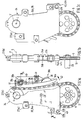
- the chain drive unit shown in the figures contains a drive pinion 1 a chain 2, and two rails 3, 4 for the train strand and for the empty strand of the chain 2, which still has at least one driven wheel 5 is led.
- This chain drive unit described is for driving one Engine auxiliary unit, not shown, provided the drive pinion 1 on the engine crankshaft, of which only the axis 6 is shown, secured against rotation is. Via the drive pinion 1, the axis of which corresponds to the crankshaft axis 6 coincides, thus the rotational movement of the engine crankshaft transferred to the chain 2 and from this to the driven wheel 5, be attached to a shaft 23 of the auxiliary unit to be driven can.
- This auxiliary unit can, for example, be an oil pump act.
- the two rails 3, 4 of the chain drive unit form an assembly 34 summarized, the end walls 35 at least the two sections essentially U-shaped rails 3, 4 connect with each other. As particularly shown in FIG. 1d, these are Rails 3, 4 designed such that the chain 2 guided therein the assembly 34 can position in the crankshaft axis direction 6. In the radial direction of the On the other hand, the crankshaft is the assembly 34 indirectly on a not shown Stored shaft of the crankshaft, also not shown, and via the drive pinion 1 attached to the crankshaft stump, which, with its side collars 1 ', the two end walls 35 the unit 34 penetrates. Incidentally, the storage of Chain drive unit described here expressly on the already mentioned referred to German patent application 196 31 875.
- tensioning lever 36 the one with its inner longitudinal edge over a longer section of chain 2 on the outside of this chain 2 comes to the concern.
- This tensioning lever 36 thus acts as a chain tensioner for the empty strand of the chain 2.
- the tensioning lever 36 is on his one end is pivotally suspended around a so-called storage area 37, the pivoting movement about a perpendicular to the end walls 35 Axis can take place and the storage area 37 - like FIGS. 1a, 1d show - is provided between the two walls 35.
- FIG Unit 34 receives the assembly 34 in the Level of symmetry 13 of the chain drive is divided and is formed by several clip connections 27 held together.
- the front in Fig. 1a Part 34a of the assembly 34 is thus u. a. from the front wall 35 as well as half a U-profile of the two rails 3 and 4, while the rear part 34b of the assembly 34 closes these two rails 3 and 4 completed a complete U-profile and continue the rear wall 35 of Unit 34 contains.
- the rail 3 leads the train of the chain 2
- the rail 3 is the so-called guide rail of the chain drive.
- FIG. 1d As far as the storage area 37 is concerned, it can be seen in FIG. 1d that a Bearing bush 37a on the opposite, from the walls 35 inwardly projecting bearing webs 37b of the front part 34a and of the rear part 34b is arranged. Then on the bearing bush 37a the clamping lever 36 with its circular bearing eye, not designated mounted pivotably about the axis 37c of the storage area 37.
- this axis 37c has a centering pin 35a which leads to the inside the wall 35 of the front part 34a is formed and in a corresponding Passage opening engages in the wall 35 of the rear part 34b.
- a comparable centering pin 35a can also be found in FIG left-hand area of the assembly 34, which in the rest in particular can be formed from plastic injection molding.
- centering pins 35a Among other things in the area of these centering pins 35a are clip connections 27 provided, namely here in the form of so-called spring clips 27a, which the Grip assembly 34 on the outside and also by the corresponding shaped centering pins 35a are guided.
- Another clip connection 27 is located approximately in the middle of the wall 35 of the assembly 34, where - as in particular Fig. 1d shows - on the inside of the wall 35 of the front part 34a plastic clips 27b are molded into a corresponding recess engage in the rear wall 35.
- plastic clips 27b can also be found at the upper end of the assembly 34 (see FIG. 1a, 1b).
- the spring element 38 is mounted directly in the bearing area 37 of the tensioning lever 36, specifically concentrically to it. As can be seen, the spring element 38 engages with its first end 38a on the outside of the clamping lever 36, which is shaped as a circular cylinder in this area. Furthermore, in this first embodiment, the spring element 38 is guided in the vicinity of this bearing area 37 between two stop pins 40. In the exemplary embodiment according to FIG. 2, the spring element 38 is mounted differently, specifically here the first end 38a is clamped between the two upper stop pins 40 arranged differently from FIG.
- At least one further stop point 41 is provided for the spring element 38.
- This at least one further attachment point 41 is located on the side facing away from the tensioning lever 36 with respect to the spring element 38 designed in the manner of a bending rod. With the help of this attachment point 41, a stepped spring characteristic can be achieved. With a slight deflection of the tensioning lever 36, a relatively long section of the flexible rod-like spring element 38 is initially relevant, namely essentially the section lying between the support point 39 and the bearing area of the spring element 38. A relatively soft spring characteristic can thus be achieved.
- Reference numeral 43 generally designates a fastening for preventing the assembly 34 from pivoting.
- the structural unit 34 is essentially guided only by the chain 2 after only the drive pinion 1 and the driven wheel 5 are connected to the internal combustion engine.
- the drive pinion 1 is located on the crankshaft, not shown, while the driven wheel 5 is flanged on a shaft 23 of the auxiliary unit, not shown, which is also fastened to the internal combustion engine.
- the assembly 34 is not connected to the internal combustion engine, but rather is positioned or guided by the chain 2 guided on the drive pinion 1 and the driven gear 5.
- the assembly 34 shown can thus be in or perform slight oscillating movements about the crankshaft axis 6 in the direction of the arrow 42, after the structural unit 34 shown is not connected in any way to the driven wheel 5 or to the shaft 23 of the auxiliary unit. It should be expressly pointed out that, in certain cases, such oscillating movements of the assembly 34 need not be disruptive at all. In these cases, the attachment 43 now described is not required at all. If such small oscillating movements of the assembly 34 are undesirable, for example in order to be able to actually set a defined chain tension by the tensioning lever 36, the attachment 43 can be provided which prevents the described pivoting of the assembly 34 in or against the direction of the arrow 42.
- This fastening 43 consists of a recess 43a provided in the end walls 35 of the structural unit 34, into which a pin 43b which is attached to a suitable point on the internal combustion engine and extends in the longitudinal direction of the crankshaft axis 6 engages.
- the attachment 43 can, however, also be designed in such a way that this assembly 34 in the area of the driven gear 35 is similar to that in the area of the drive pinion 1, so that pivoting of the assembly 34 either through the driven gear 5 or through the associated shaft 23 is prevented.
- no such attachment 43 can alternatively be provided to prevent the pivoting.
- the assembly 34 can also be non-divisible, i. H. as quasi closed component are produced, but then in one of the end walls 35 a suitable recess for inserting the drive pinion 1 must be provided.
- this entire chain drive unit consisting of the assembly 34, the drive pinion 1, the Output gear 5, the chain 2, and the tensioning lever 36 with the spring element 38 designed as a pre-assembly unit in a chain shaft of an internal combustion engine be used as is for a simplified embodiment already in the aforementioned German patent application 196 31 875 is described.
- Can also be used for lubrication and cooling the chain 2 in the assembly 34 suitable openings or openings (Not shown) may be provided via the circulated in the internal combustion engine Lubricating oil, especially that running back from the cylinder head into the oil pan Lubricating oil gets into the assembly 34 and so not only the Chain 2, but also the movable components of the assembly 34 reached.
Landscapes
- Engineering & Computer Science (AREA)
- General Engineering & Computer Science (AREA)
- Mechanical Engineering (AREA)
- Chemical & Material Sciences (AREA)
- Combustion & Propulsion (AREA)
- Devices For Conveying Motion By Means Of Endless Flexible Members (AREA)
Applications Claiming Priority (2)
| Application Number | Priority Date | Filing Date | Title |
|---|---|---|---|
| DE19731809 | 1997-07-24 | ||
| DE19731809 | 1997-07-24 |
Publications (3)
| Publication Number | Publication Date |
|---|---|
| EP0893588A2 true EP0893588A2 (fr) | 1999-01-27 |
| EP0893588A3 EP0893588A3 (fr) | 1999-11-10 |
| EP0893588B1 EP0893588B1 (fr) | 2002-12-11 |
Family
ID=7836741
Family Applications (1)
| Application Number | Title | Priority Date | Filing Date |
|---|---|---|---|
| EP98111216A Expired - Lifetime EP0893588B1 (fr) | 1997-07-24 | 1998-06-18 | Module d'entrainement par chaine pour un moteur à combustion interne |
Country Status (2)
| Country | Link |
|---|---|
| EP (1) | EP0893588B1 (fr) |
| DE (1) | DE59806596D1 (fr) |
Cited By (5)
| Publication number | Priority date | Publication date | Assignee | Title |
|---|---|---|---|---|
| EP1367227A3 (fr) * | 2002-05-07 | 2003-12-10 | Joh. Winklhofer & SöhneGmbH und Co.KG | Entraínement par chaíne pré-assemblé avec une aide pour son montage |
| DE10341966A1 (de) * | 2003-09-11 | 2005-04-21 | Bayerische Motoren Werke Ag | Kettenführungseinrichtung, insbesondere für eine Steuerkette |
| WO2008019205A1 (fr) * | 2006-08-11 | 2008-02-14 | Borgwarner Inc | Système et procédé d'assemblage pour système d'entraînement à chaîne tendue |
| DE102014201667A1 (de) * | 2014-01-30 | 2015-07-30 | Schaeffler Technologies AG & Co. KG | Spannvorrichtung für Zugmitteltrieb |
| DE102018130732A1 (de) * | 2018-11-23 | 2020-05-28 | Iwis Motorsysteme Gmbh & Co. Kg | Montagemodul mit Hakenelement |
Citations (1)
| Publication number | Priority date | Publication date | Assignee | Title |
|---|---|---|---|---|
| DE19631875A1 (de) | 1996-08-07 | 1998-02-12 | Bayerische Motoren Werke Ag | Kettentrieb-Einheit für eine Brennkraftmaschine |
Family Cites Families (4)
| Publication number | Priority date | Publication date | Assignee | Title |
|---|---|---|---|---|
| FR2496814B1 (fr) * | 1980-12-19 | 1985-12-13 | Sedis Transmissions Meca | Dispositif de tension et de guidage pour chaine ou courroie sans fin |
| FR2545193B1 (fr) * | 1983-04-29 | 1986-10-31 | Sedis Transmissions Mecaniques | Boitier amovible de distribution pour moteur a explosion ou a combustion |
| DE3816864A1 (de) * | 1988-05-18 | 1989-11-23 | Daimler Benz Ag | Spannvorrichtung fuer einen kettentrieb |
| JPH06299863A (ja) * | 1993-04-16 | 1994-10-25 | Suzuki Motor Corp | オイルポンプ駆動チェーンガイド |
-
1998
- 1998-06-18 DE DE59806596T patent/DE59806596D1/de not_active Expired - Lifetime
- 1998-06-18 EP EP98111216A patent/EP0893588B1/fr not_active Expired - Lifetime
Patent Citations (1)
| Publication number | Priority date | Publication date | Assignee | Title |
|---|---|---|---|---|
| DE19631875A1 (de) | 1996-08-07 | 1998-02-12 | Bayerische Motoren Werke Ag | Kettentrieb-Einheit für eine Brennkraftmaschine |
Cited By (8)
| Publication number | Priority date | Publication date | Assignee | Title |
|---|---|---|---|---|
| EP1367227A3 (fr) * | 2002-05-07 | 2003-12-10 | Joh. Winklhofer & SöhneGmbH und Co.KG | Entraínement par chaíne pré-assemblé avec une aide pour son montage |
| US6955622B2 (en) | 2002-05-07 | 2005-10-18 | H. Winklhofer & Sohne Gmbh And Co. Kg | Preassembled drive means unit including a mounting aid |
| DE10341966A1 (de) * | 2003-09-11 | 2005-04-21 | Bayerische Motoren Werke Ag | Kettenführungseinrichtung, insbesondere für eine Steuerkette |
| WO2008019205A1 (fr) * | 2006-08-11 | 2008-02-14 | Borgwarner Inc | Système et procédé d'assemblage pour système d'entraînement à chaîne tendue |
| CN101495775B (zh) * | 2006-08-11 | 2011-09-07 | 博格华纳公司 | 用于一种张紧的链驱动系统的组装系统及方法 |
| US8387244B2 (en) | 2006-08-11 | 2013-03-05 | Borgwarner Inc. | Assembly system and method for a tensioned chain drive system |
| DE102014201667A1 (de) * | 2014-01-30 | 2015-07-30 | Schaeffler Technologies AG & Co. KG | Spannvorrichtung für Zugmitteltrieb |
| DE102018130732A1 (de) * | 2018-11-23 | 2020-05-28 | Iwis Motorsysteme Gmbh & Co. Kg | Montagemodul mit Hakenelement |
Also Published As
| Publication number | Publication date |
|---|---|
| EP0893588B1 (fr) | 2002-12-11 |
| DE59806596D1 (de) | 2003-01-23 |
| EP0893588A3 (fr) | 1999-11-10 |
Similar Documents
| Publication | Publication Date | Title |
|---|---|---|
| DE60109309T2 (de) | Riemenspanner | |
| DE2914748A1 (de) | Spiel-nachstellvorrichtung fuer ein endoskop | |
| DE3832955C2 (fr) | ||
| DE3119532A1 (de) | Fensterkurbelvorrichtung mit biegsamer schraubspindel | |
| DE3942383C2 (de) | Spannvorrichtung | |
| EP0793002B1 (fr) | Dispositif préassemblé d'entraínement par chaíne d'arbre à cames de moteur à combustion interne | |
| DE102018130732A1 (de) | Montagemodul mit Hakenelement | |
| EP0823543B1 (fr) | Unité d'entraínement à chaíne pour un moteur à combustion interne | |
| EP0893588B1 (fr) | Module d'entrainement par chaine pour un moteur à combustion interne | |
| DE102008061993A1 (de) | Industrieroboter | |
| EP0779450B1 (fr) | Tendeur hydraulique pour organes flexibles d'entraínement d'un arbre à cames | |
| DE1500447B1 (de) | Kettenspanner | |
| DE102008011369A1 (de) | Befestigungsvorrichtung für eine Zugmittel-Spannvorrichtung | |
| DE102006017522B4 (de) | Luftleiteinrichtung für ein Fahrzeug | |
| DE19501561A1 (de) | Einrichtung zur Transformation einer Vor- und Rückwärtsbewegung in eine Drehbewegung | |
| DE19600441C2 (de) | Zylinderkopf einer Brennkraftmaschine | |
| DE69401234T2 (de) | Gegenschwingungslager mit Vorrichtung zur Begrenzung der Dehnungsbewegungen | |
| DE69405207T2 (de) | Dachpanelvorrichtung | |
| DE2649880C3 (de) | Kettenspannvorrichtung | |
| DE1226850B (de) | Kettenspanner, insbesondere fuer die Kette des Nockenwellenantriebs von Brennkraftmaschinen | |
| DE102017111948A1 (de) | Transportsicherung für eine hydraulische Spannvorrichtung | |
| DE19606002A1 (de) | Spann- oder Gleitschiene für Kettentriebe von Brennkraftmaschinen | |
| EP0433702A2 (fr) | Mécanisme de levier | |
| DE2252895B2 (de) | Kupplungsvorrichtung für Angelrollen | |
| DE4220417A1 (de) | Mechanische Zahnstangenlenkung |
Legal Events
| Date | Code | Title | Description |
|---|---|---|---|
| PUAI | Public reference made under article 153(3) epc to a published international application that has entered the european phase |
Free format text: ORIGINAL CODE: 0009012 |
|
| AK | Designated contracting states |
Kind code of ref document: A2 Designated state(s): DE FR GB IT |
|
| AX | Request for extension of the european patent |
Free format text: AL;LT;LV;MK;RO;SI |
|
| PUAL | Search report despatched |
Free format text: ORIGINAL CODE: 0009013 |
|
| AK | Designated contracting states |
Kind code of ref document: A3 Designated state(s): AT BE CH CY DE DK ES FI FR GB GR IE IT LI LU MC NL PT SE |
|
| AX | Request for extension of the european patent |
Free format text: AL;LT;LV;MK;RO;SI |
|
| 17P | Request for examination filed |
Effective date: 20000214 |
|
| AKX | Designation fees paid |
Free format text: DE FR GB IT |
|
| 17Q | First examination report despatched |
Effective date: 20020115 |
|
| GRAG | Despatch of communication of intention to grant |
Free format text: ORIGINAL CODE: EPIDOS AGRA |
|
| GRAG | Despatch of communication of intention to grant |
Free format text: ORIGINAL CODE: EPIDOS AGRA |
|
| GRAH | Despatch of communication of intention to grant a patent |
Free format text: ORIGINAL CODE: EPIDOS IGRA |
|
| GRAH | Despatch of communication of intention to grant a patent |
Free format text: ORIGINAL CODE: EPIDOS IGRA |
|
| GRAA | (expected) grant |
Free format text: ORIGINAL CODE: 0009210 |
|
| AK | Designated contracting states |
Kind code of ref document: B1 Designated state(s): DE FR GB IT |
|
| REG | Reference to a national code |
Ref country code: GB Ref legal event code: FG4D Free format text: NOT ENGLISH |
|
| REF | Corresponds to: |
Ref document number: 59806596 Country of ref document: DE Date of ref document: 20030123 |
|
| GBT | Gb: translation of ep patent filed (gb section 77(6)(a)/1977) |
Effective date: 20030121 |
|
| ET | Fr: translation filed | ||
| PLBE | No opposition filed within time limit |
Free format text: ORIGINAL CODE: 0009261 |
|
| STAA | Information on the status of an ep patent application or granted ep patent |
Free format text: STATUS: NO OPPOSITION FILED WITHIN TIME LIMIT |
|
| 26N | No opposition filed |
Effective date: 20030912 |
|
| PGFP | Annual fee paid to national office [announced via postgrant information from national office to epo] |
Ref country code: IT Payment date: 20120626 Year of fee payment: 15 |
|
| PG25 | Lapsed in a contracting state [announced via postgrant information from national office to epo] |
Ref country code: IT Free format text: LAPSE BECAUSE OF NON-PAYMENT OF DUE FEES Effective date: 20130618 |
|
| REG | Reference to a national code |
Ref country code: FR Ref legal event code: PLFP Year of fee payment: 18 |
|
| PGFP | Annual fee paid to national office [announced via postgrant information from national office to epo] |
Ref country code: GB Payment date: 20150630 Year of fee payment: 18 Ref country code: DE Payment date: 20150615 Year of fee payment: 18 |
|
| PGFP | Annual fee paid to national office [announced via postgrant information from national office to epo] |
Ref country code: FR Payment date: 20150629 Year of fee payment: 18 |
|
| REG | Reference to a national code |
Ref country code: DE Ref legal event code: R119 Ref document number: 59806596 Country of ref document: DE |
|
| GBPC | Gb: european patent ceased through non-payment of renewal fee |
Effective date: 20160618 |
|
| REG | Reference to a national code |
Ref country code: FR Ref legal event code: ST Effective date: 20170228 |
|
| PG25 | Lapsed in a contracting state [announced via postgrant information from national office to epo] |
Ref country code: FR Free format text: LAPSE BECAUSE OF NON-PAYMENT OF DUE FEES Effective date: 20160630 Ref country code: DE Free format text: LAPSE BECAUSE OF NON-PAYMENT OF DUE FEES Effective date: 20170103 |
|
| PG25 | Lapsed in a contracting state [announced via postgrant information from national office to epo] |
Ref country code: GB Free format text: LAPSE BECAUSE OF NON-PAYMENT OF DUE FEES Effective date: 20160618 |