EP0893596B1 - Fremdgezündete Brennkraftmaschine mit Einspritzung in den Zylinder - Google Patents
Fremdgezündete Brennkraftmaschine mit Einspritzung in den Zylinder Download PDFInfo
- Publication number
- EP0893596B1 EP0893596B1 EP98113426A EP98113426A EP0893596B1 EP 0893596 B1 EP0893596 B1 EP 0893596B1 EP 98113426 A EP98113426 A EP 98113426A EP 98113426 A EP98113426 A EP 98113426A EP 0893596 B1 EP0893596 B1 EP 0893596B1
- Authority
- EP
- European Patent Office
- Prior art keywords
- combustion mode
- valve overlap
- homogeneous
- target
- stratified
- Prior art date
- Legal status (The legal status is an assumption and is not a legal conclusion. Google has not performed a legal analysis and makes no representation as to the accuracy of the status listed.)
- Expired - Lifetime
Links
Images


Classifications
-
- F—MECHANICAL ENGINEERING; LIGHTING; HEATING; WEAPONS; BLASTING
- F02—COMBUSTION ENGINES; HOT-GAS OR COMBUSTION-PRODUCT ENGINE PLANTS
- F02D—CONTROLLING COMBUSTION ENGINES
- F02D41/00—Electrical control of supply of combustible mixture or its constituents
- F02D41/30—Controlling fuel injection
- F02D41/3011—Controlling fuel injection according to or using specific or several modes of combustion
- F02D41/3017—Controlling fuel injection according to or using specific or several modes of combustion characterised by the mode(s) being used
- F02D41/3023—Controlling fuel injection according to or using specific or several modes of combustion characterised by the mode(s) being used a mode being the stratified charge spark-ignited mode
- F02D41/3029—Controlling fuel injection according to or using specific or several modes of combustion characterised by the mode(s) being used a mode being the stratified charge spark-ignited mode further comprising a homogeneous charge spark-ignited mode
-
- F—MECHANICAL ENGINEERING; LIGHTING; HEATING; WEAPONS; BLASTING
- F02—COMBUSTION ENGINES; HOT-GAS OR COMBUSTION-PRODUCT ENGINE PLANTS
- F02D—CONTROLLING COMBUSTION ENGINES
- F02D13/00—Controlling the engine output power by varying inlet or exhaust valve operating characteristics, e.g. timing
- F02D13/02—Controlling the engine output power by varying inlet or exhaust valve operating characteristics, e.g. timing during engine operation
- F02D13/0203—Variable control of intake and exhaust valves
- F02D13/0207—Variable control of intake and exhaust valves changing valve lift or valve lift and timing
-
- F—MECHANICAL ENGINEERING; LIGHTING; HEATING; WEAPONS; BLASTING
- F02—COMBUSTION ENGINES; HOT-GAS OR COMBUSTION-PRODUCT ENGINE PLANTS
- F02D—CONTROLLING COMBUSTION ENGINES
- F02D13/00—Controlling the engine output power by varying inlet or exhaust valve operating characteristics, e.g. timing
- F02D13/02—Controlling the engine output power by varying inlet or exhaust valve operating characteristics, e.g. timing during engine operation
- F02D13/0223—Variable control of the intake valves only
- F02D13/0234—Variable control of the intake valves only changing the valve timing only
- F02D13/0238—Variable control of the intake valves only changing the valve timing only by shifting the phase, i.e. the opening periods of the valves are constant
-
- F—MECHANICAL ENGINEERING; LIGHTING; HEATING; WEAPONS; BLASTING
- F02—COMBUSTION ENGINES; HOT-GAS OR COMBUSTION-PRODUCT ENGINE PLANTS
- F02D—CONTROLLING COMBUSTION ENGINES
- F02D13/00—Controlling the engine output power by varying inlet or exhaust valve operating characteristics, e.g. timing
- F02D13/02—Controlling the engine output power by varying inlet or exhaust valve operating characteristics, e.g. timing during engine operation
- F02D13/0261—Controlling the valve overlap
-
- F—MECHANICAL ENGINEERING; LIGHTING; HEATING; WEAPONS; BLASTING
- F02—COMBUSTION ENGINES; HOT-GAS OR COMBUSTION-PRODUCT ENGINE PLANTS
- F02D—CONTROLLING COMBUSTION ENGINES
- F02D41/00—Electrical control of supply of combustible mixture or its constituents
- F02D41/0025—Controlling engines characterised by use of non-liquid fuels, pluralities of fuels, or non-fuel substances added to the combustible mixtures
- F02D41/0047—Controlling exhaust gas recirculation [EGR]
- F02D41/006—Controlling exhaust gas recirculation [EGR] using internal EGR
-
- F—MECHANICAL ENGINEERING; LIGHTING; HEATING; WEAPONS; BLASTING
- F02—COMBUSTION ENGINES; HOT-GAS OR COMBUSTION-PRODUCT ENGINE PLANTS
- F02D—CONTROLLING COMBUSTION ENGINES
- F02D41/00—Electrical control of supply of combustible mixture or its constituents
- F02D41/30—Controlling fuel injection
- F02D41/3011—Controlling fuel injection according to or using specific or several modes of combustion
- F02D41/3064—Controlling fuel injection according to or using specific or several modes of combustion with special control during transition between modes
-
- F—MECHANICAL ENGINEERING; LIGHTING; HEATING; WEAPONS; BLASTING
- F01—MACHINES OR ENGINES IN GENERAL; ENGINE PLANTS IN GENERAL; STEAM ENGINES
- F01L—CYCLICALLY OPERATING VALVES FOR MACHINES OR ENGINES
- F01L1/00—Valve-gear or valve arrangements, e.g. lift-valve gear
- F01L1/34—Valve-gear or valve arrangements, e.g. lift-valve gear characterised by the provision of means for changing the timing of the valves without changing the duration of opening and without affecting the magnitude of the valve lift
- F01L1/344—Valve-gear or valve arrangements, e.g. lift-valve gear characterised by the provision of means for changing the timing of the valves without changing the duration of opening and without affecting the magnitude of the valve lift changing the angular relationship between crankshaft and camshaft, e.g. using helicoidal gear
-
- F—MECHANICAL ENGINEERING; LIGHTING; HEATING; WEAPONS; BLASTING
- F01—MACHINES OR ENGINES IN GENERAL; ENGINE PLANTS IN GENERAL; STEAM ENGINES
- F01L—CYCLICALLY OPERATING VALVES FOR MACHINES OR ENGINES
- F01L2201/00—Electronic control systems; Apparatus or methods therefor
-
- F—MECHANICAL ENGINEERING; LIGHTING; HEATING; WEAPONS; BLASTING
- F02—COMBUSTION ENGINES; HOT-GAS OR COMBUSTION-PRODUCT ENGINE PLANTS
- F02B—INTERNAL-COMBUSTION PISTON ENGINES; COMBUSTION ENGINES IN GENERAL
- F02B2275/00—Other engines, components or details, not provided for in other groups of this subclass
- F02B2275/18—DOHC [Double overhead camshaft]
-
- F—MECHANICAL ENGINEERING; LIGHTING; HEATING; WEAPONS; BLASTING
- F02—COMBUSTION ENGINES; HOT-GAS OR COMBUSTION-PRODUCT ENGINE PLANTS
- F02D—CONTROLLING COMBUSTION ENGINES
- F02D41/00—Electrical control of supply of combustible mixture or its constituents
- F02D41/0002—Controlling intake air
- F02D2041/001—Controlling intake air for engines with variable valve actuation
-
- F—MECHANICAL ENGINEERING; LIGHTING; HEATING; WEAPONS; BLASTING
- F02—COMBUSTION ENGINES; HOT-GAS OR COMBUSTION-PRODUCT ENGINE PLANTS
- F02D—CONTROLLING COMBUSTION ENGINES
- F02D41/00—Electrical control of supply of combustible mixture or its constituents
- F02D41/30—Controlling fuel injection
- F02D41/38—Controlling fuel injection of the high pressure type
- F02D2041/389—Controlling fuel injection of the high pressure type for injecting directly into the cylinder
-
- Y—GENERAL TAGGING OF NEW TECHNOLOGICAL DEVELOPMENTS; GENERAL TAGGING OF CROSS-SECTIONAL TECHNOLOGIES SPANNING OVER SEVERAL SECTIONS OF THE IPC; TECHNICAL SUBJECTS COVERED BY FORMER USPC CROSS-REFERENCE ART COLLECTIONS [XRACs] AND DIGESTS
- Y02—TECHNOLOGIES OR APPLICATIONS FOR MITIGATION OR ADAPTATION AGAINST CLIMATE CHANGE
- Y02T—CLIMATE CHANGE MITIGATION TECHNOLOGIES RELATED TO TRANSPORTATION
- Y02T10/00—Road transport of goods or passengers
- Y02T10/10—Internal combustion engine [ICE] based vehicles
- Y02T10/12—Improving ICE efficiencies
-
- Y—GENERAL TAGGING OF NEW TECHNOLOGICAL DEVELOPMENTS; GENERAL TAGGING OF CROSS-SECTIONAL TECHNOLOGIES SPANNING OVER SEVERAL SECTIONS OF THE IPC; TECHNICAL SUBJECTS COVERED BY FORMER USPC CROSS-REFERENCE ART COLLECTIONS [XRACs] AND DIGESTS
- Y02—TECHNOLOGIES OR APPLICATIONS FOR MITIGATION OR ADAPTATION AGAINST CLIMATE CHANGE
- Y02T—CLIMATE CHANGE MITIGATION TECHNOLOGIES RELATED TO TRANSPORTATION
- Y02T10/00—Road transport of goods or passengers
- Y02T10/10—Internal combustion engine [ICE] based vehicles
- Y02T10/40—Engine management systems
Definitions
- the present invention relates to an in-cylinder direct-injection spark-ignition engine according to the preamble of independent claim 1.
- Such an in-cylinder direct-injection spark-ignition engine can be taken from JP 04-183945.
- a combustion mode is switchable between a homogeneous combustion mode and a stratified combustion mode, depending on engine operating conditions, such as engine speed and load.
- the direct-injection spark-ignition engine uses two combustion modes, namely an early injection combustion mode (or a homogeneous combustion mode) where fuel-injection early in the intake stroke produces a homogeneous air-fuel mixture, and a late injection combustion mode (or a stratified combustion mode) where late fuel-injection delays the event until near the end of the compression stroke to produce a stratified air-fuel mixture.
- Japanese Patent Provisional Publication No. 4-183945 teaches selecting a stratified combustion mode from at least two combustion modes as previously discussed, during engine operation at partial loads, and also teaches increasing a valve overlap, during which the open periods of the intake and exhaust valves are overlapped, by means of a variable valve timing control device located on at least one of intake and exhaust valves during the stratified combustion mode.
- the increased valve overlap in the stratified combustion mode results in an increase in a so-called internal exhaust-gas recirculation, thus suppressing a temperature rise in the exhaust temperature (or the combustion temperature).
- valve overlap is set at a comparatively large valve overlap during the stratified combustion mode (or during partial loads), whereas the valve overlap is set at a comparatively small valve overlap during the homogeneous combustion mode (or during high loads).
- the prior art control system suffers from the following drawbacks.
- Prior art document WO 96 36802 A discloses a control apparatus that changes the fuel injection mode of a cylinder-injection spark-ignition internal combustion engine without causing a misfire or smoke, lowering the exhaust characteristics or fuel-efficiency, or bringing about a changeover shock.
- An electronic control unit of the control apparatus sets a first-term injection mode for fuel injection in a suction stroke or a second-term injection mode for fuel injection in a compression stroke in accordance with the engine operation state, and sets the values of parameters, such as the fuel injection quantity, ignition timing, exhaust gas recirculation quantity, etc., which are concerned in the combustion state in the engine, at values suitable for the set injection mode, thereby controlling the engine operation.
- the parameter values are changed from the values suitable for the injection mode before change into the values suitable for the injection mode after change at suitable timings. According such change of values the change of the injection mode is delayed in order to prevent causing a misfire or smoke.
- an in-cylinder direct-injection spark-ignition engine with an electronic concentrated engine control system employing an electronic fuel injection system used to switch between a homogeneous combustion mode and a stratified combustion mode is capable of optimizing a switch timing of a valve overlap being variably adjusted depending on whether the combustion mode is the homogeneous combustion mode or the stratified combustion mode.
- the in-cylinder direct-injection spark-ignition engine is provided with an electronic concentrated engine control system employing an electronic fuel injection system used to switch between a homogeneous lean combustion mode and a homogeneous stoichiometric combustion mode and a stratified combustion mode (a lean stratified combustion mode), which is capable of optimizing a switch timing of a valve overlap being variably adjusted depending whether the combustion mode is the homogeneous lean combustion mode, the homogeneous stoichiometric combustion mode or the lean stratified combustion mode.
- an electronic concentrated engine control system employing an electronic fuel injection system used to switch between a homogeneous lean combustion mode and a homogeneous stoichiometric combustion mode and a stratified combustion mode (a lean stratified combustion mode), which is capable of optimizing a switch timing of a valve overlap being variably adjusted depending whether the combustion mode is the homogeneous lean combustion mode, the homogeneous stoichiometric combustion mode or the lean stratified combustion mode.
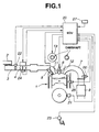
- the opening and closing of the electronically-controlled throttle 4 is controlled generally by means of a stepper motor (also known as a “stepping motor” or a “step-servo motor”).
- the stepper motor of the electronically-controlled throttle 4 is connected via a signal line to the output interface (or a drive circuit) of an electronic control unit (ECU) 20, so that the angular steps or essentially uniform angular movements of the stepper motor (not numbered) can be obtained electromagnetically depending on a control signal (or a drive signal) from the output interface of the control unit 20.
- the electronic fuel-injection system of the direct-injection engine 1 comprises an electromagnetic fuel-injection valve (simply an electromagnetic fuel injector) 5 is provided at each engine cylinder, so that fuel (gasoline) can be injected directly into each combustion chamber.
- the amount of fuel injected from the electromagnetic fuel injector 5 into the associated engine cylinder is controlled by the pulse-width time (a controlled duty cycle or duty ratio) of a pulsewidth modulated (PWM) voltage signal (simply an injection pulse signal).
- PWM pulsewidth modulated
- the output interface of the electronic control unit 20 generates the injection pulse signal on the intake stroke and on the compression stroke, in synchronization with revolutions of the engine.
- the electromagnetic solenoid of the fuel injector 5 is energized and de-energized by the duty cycle pulsewidth modulated (PWM) voltage signal (the injector pulse signal) at a controlled duty cycle.
- PWM duty cycle pulsewidth modulated
- the valve opening time of the fuel injector 5 can be controlled by way of the controlled duty cycle and also the fuel, regulated to a desired pressure level, can be injected via the fuel injector and delivered directly into the associated engine cylinder.
- the direct-injection engine 1 of the embodiment uses at least two combustion modes, one being an early injection combustion mode (or a homogeneous combustion mode) where fuel-injection early in the intake stroke produces a homogeneous air-fuel mixture, and the other being a late injection combustion mode (or a stratified combustion mode) where late fuel-injection delays the event until near the end of the compression stroke to produce a stratified air-fuel mixture.
- an early injection combustion mode or a homogeneous combustion mode
- a late injection combustion mode or a stratified combustion mode
- the incoming air mixes with the denser fuel spray due to the late injection in the compression stroke, to create a rich mixture around a spark plug 6 for easy ignition, while the rest of the air-fuel mixture after late injection is very lean at edges of the combustion chamber.
- the ignition system of the direct-injection engine 1 is responsive to an ignition signal from the ECU 20, for igniting the air-fuel mixture to ensure the homogeneous combustion on the intake stroke and to ensure the stratified combustion on the compression stroke. Roughly speaking, the combustion modes are classified into a homogeneous combustion mode and a stratified combustion mode.
- the homogeneous combustion modes are further classified into a homogeneous stoichiometric combustion mode and a homogeneous lean combustion mode.
- the air/fuel ratio of the homogeneous stoichiometric combustion mode is 14.6:1 air/fuel ratio (AFR).
- the air/fuel ratio of the homogeneous lean combustion mode is 20:1 to 30:1 AFR (preferably 15:1 to 22:1 AFR).
- the air/fuel ratio of the stratified combustion mode (exactly the lean stratified combustion mode or the ultra-lean stratified combustion mode) is 25:1 to 50:1 (preferably 40:1 AFR).
- the burnt gases is exhausted from the engine cylinder into the exhaust passage 7.
- variable valve timing control device (VTC) 13 is mounted on at least one of the intake valve 11 and the exhaust valve 12.
- the variable valve timing control device 13 is provided at the front end of the intake camshaft (the left-hand camshaft in Fig. 1) involved in the intake-valve operating mechanism.
- the variable valve timing control device 13 is operated in response to a control signal (or a command signal) from the ECU 20, for properly advancing or retarding the timing of the intake valve 11.
- the electronic concentrated engine control system of the shown embodiment uses a conventional variable valve timing control device in which the opening and closing timings can be advanced or retarded by varying the angular phase between the camshaft and the cam sprocket (that is, the angular phase between the camshaft and the crankshaft), while retaining the valve lift unchanged.
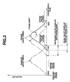
- a variable valve timing control device 13 mounted on the front end of the intake camshaft, assuming that the timing of the intake valve 11 is advanced by a desired phase shift, a valve overlap, during which the open periods of the intake (11) and exhaust (12) valves are overlapped, simultaneously varies with phase advance, as seen in Fig. 2.
- variable valve lift device or a variable valve timing plus lift device may be used as a variable valve overlap device.
- Typical details of such a variable valve timing control device being set forth, for example, in U.S. Pat. No. 5,088,456 issued February 18, 1992 to Seiji Suga.
- the electronic control unit 20 comprises a microcomputer, generally constructed by a central processing unit (CPU), a read only memory (ROM), a random access memory (RAM), an analog-to-digital converter, an input/output interface circuitry (or input/output interface unit), and the like.
- the input interface of the control unit 20 receives various signals from engine/vehicle sensors, namely a crank angle sensor 21, an air flow meter 22, an accelerator position sensor (or an accelerator sensor) 23, a throttle sensor 24, a coolant temperature sensor 25, an oxygen sensor (O 2 sensor) 26, and a vehicle speed sensor 27.
- the crank angle sensor 21 is provided for detecting revolutions of the engine crankshaft (or the rotation of the camshaft).
- the crank angle sensor 21 Assuming that the number of engine cylinders is "n", the crank angle sensor 21 generates a reference pulse signal REF at a predetermined crank angle for every crank angle 720°/n, and simultaneously generates a unit pulse signal POS (1° signal or 2° signal) for every unit crank angle (1° or 2°).
- the CPU of the control unit 20 arithmetically calculates an engine speed Ne for example on the basis of the period of the reference pulse signal REF from the crank angle sensor 21.
- the air flow meter 22 is provided in the intake-air passage 22 upstream of the electronically-controlled throttle 4, to generates an intake-air flow rate signal indicative of an actual intake-air flow rate (or an actual air quantity) Qa.
- the accelerator position sensor 23 is located near the accelerator pedal to detect an accelerator opening ACC (i.e., a depression amount of the accelerator pedal).
- the throttle sensor 24 is located near the electronically-controlled throttle 4 to generate a throttle sensor signal indicative of a throttle opening TVO which is generally defined as a ratio of an actual throttle angle to a throttle angle obtained at wide open throttle.
- the throttle sensor 24 involves an idle switch (not numbered) which is switched ON with the throttle 4 fully closed.
- the coolant temperature sensor 25 is located on the engine 1 (for example on the engine block) to sense the actual operating temperature (coolant temperature Tw) of the engine 1.
- the vehicle speed sensor 27 generates a vehicle speed sensor signal indicative of a vehicle speed VSP.
- the exhaust gas oxygen sensor 26 is located in the exhaust passage 7, to monitor the percentage of oxygen contained within the exhaust gases at all times when the engine 1 is running, and to produce input information representative of how far the actual air-fuel ratio (AFR) deviates from the closed-loop stoichiometric air-fuel ratio (12.6:1).
- AFR actual air-fuel ratio
- the voltage signal from the O 2 sensor 26 is used by the engine control unit (ECU).
- ECU engine control unit
- a voltage level of the voltage signal generated from the O 2 sensor 26 is different depending on the oxygen content (high oxygen or low oxygen) in the engine exhaust gases. In case of lean air-fuel mixture (high oxygen concentration), the O 2 sensor 26 generates a low voltage signal.
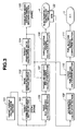
- a target combustion mode setting section 102 selects a desired combustion mode from a homogeneous stoichiometric combustion mode, a homogeneous lean combustion mode, and a lean stratified combustion mode (a ultra-lean stratified combustion mode) by reference to a predetermined or preprogrammed combustion mode map representative of the relationship among the engine speed Ne, the target torque tTe, and the desired combustion mode.
- a plurality of combustion mode maps are preprogrammed for each coolant temperatures Tw and for each elapsed time from engine starting, and stored in the predetermined memory addresses. Therefore, either one of the preprogrammed combustion mode maps is selected depending on the additional parameters, such as the coolant temperature Tw, and the elapsed time from engine starting.
- a basic equivalent ratio setting section 103 sets or arithmetically calculates a basic equivalent ratio TFBYA0 based on both the engine speed Ne and the target torque tTe, by reference to the selected one of predetermined characteristic maps, each of which is representative of the relationship among the engine speed Ne, the target torque tTe, and the basic equivalent ratio TFBYA0.
- the above-mentioned engine operating condition (Ne, tTe) versus basic equivalent ratio (TFBYA0) characteristic map is preprogrammed for each of the three combustion modes, namely the homogeneous stratified combustion mode, the homogeneous lean combustion mode, and the lean stratified combustion mode.
- the engine operating condition (Ne, tTe) versus basic equivalent ratio (TFBYA0) characteristics are different depending on the three different combustion modes, and thus the basic equivalent ratio TFBYA0 is based on the target combustion mode selected.
- the stoichiometric air/fuel ratio (often called a "Lambda point") is 14.6 : 1.
- a target equivalent ratio calculation section 104 derives or calculates a target equivalent ratio TFBYA on the basis of the basic equivalent ratio TFBYA0 calculated, from the following expression.
- TFBYA M ⁇ TFBYA 0 + ( 1 - M ) ⁇ TFBYA where M denotes a weighting factor of weighted mean
- TFBYA indicated in the left-hand side of the expression corresponds to the latest up-to-date target equivalent ratio derived at the current cycle of arithmetic processing
- TFBYA indicated in the right-hand side of the expression corresponds to the previous target equivalent ratio derived one cycle before.
- a predetermined phase-lag processing (a weighted-mean processing) is made to the basic equivalent ratio TFBYA0 to compensate for a first-order lag of the intake-air flow rate, and to ensure the phase matching between the target equivalent ratio TFBYA and the intake-air flow rate.
- a combustion mode switch timing decision section 105 comprises a comparator for comparing the target equivalent ratio TFBYA to a predetermined threshold value.
- the predetermined threshold value is different depending on whether the desired combustion mode is the homogeneous stoichiometric combustion mode, the homogeneous lean combustion mode, or the lean stratified combustion mode. Switching between the combustion modes occurs actually, when the target equivalent ratio TFBYA goes across the predetermined threshold value.
- an actual combustion mode switch flag FSTR2 is reset at "0", and at the same time the fuel injection timing is set at the intake stroke.
- the actual combustion mode switch flag FSTR2 is set at "1", and simultaneously the fuel injection timing is set at the compression stroke. In other words, an actual combustion mode is estimated depending on the sign of the flag FSTR2.
- a basic fuel quantity calculation section 106 temporarily retrieves an instantaneous basic fuel quantity on the basis of both the target torque tTe and the engine speed Ne, from a predetermined engine operating condition (Ne, tTe) versus instantaneous basic fuel quantity characteristic map. Additionally, the basic fuel quantity calculation section 106 compensates for the instantaneous basic fuel quantity depending on the air/fuel ratio (AFR), since the air/fuel ratio remarkably varies depending on whether the combustion mode is the homogeneous combustion mode or the stratified combustion mode. The compensated basic fuel quantity is set at a basic fuel quantity tQf.
- a target air quantity per cylinder calculation section 107 arithmetically calculates a target quantity of air to be supplied into an engine cylinder on the basis of both the basic fuel quantity tQf and the target equivalent ratio TFBYA, from the following expression.
- t Q cyl t Q f ⁇ ( 14.6 / T F B Y A )
- a target throttle opening calculation section 108 retrieves a target throttle opening tTVO on the basis of both the target air quantity per cylinder tQcyl and the engine speed Ne, from a predetermined or preprogrammed characteristic map representative of the relationship among the target air quantity per cylinder tQcyl, the engine speed Ne, and the target throttle opening tTVO.
- the target throttle opening calculation section 108 sends out a command signal based on the calculated target throttle opening (tTVO) to the stepper motor of the electronically-controlled throttle 4 to adjust the throttle opening of the throttle 4 toward the calculated target throttle opening tTVO by virtue of the angular movement of the stepper motor.
- the actual intake-air flow rate Qa is detected or measured by the air flow meter 22.
- An air quantity per cylinder calculation section 109 divides the actual intake-air quantity Qa by the engine speed Ne, and then makes a smoothing and phase-lag processing with respect to the divided value (Qa/Ne) to calculate a quantity-of-air Qcyl supplied into an engine cylinder.
- a target fuel-injection amount calculation section 110 arithmetically calculates an instantaneous target fuel-injection amount tQfi based on both the air quantity per cylinder Qcyl and the target equivalent ratio TFBYA, from the following expression.
- K is a predetermined constant
- K ⁇ Qcyl corresponds to a target fuel-injection amount with a stoichiometric air/fuel ratio
- an injection pulse signal (an enrichment command signal or a lean command signal) of a controlled duty cycle (a pulse-width time based on the target fuel-injection amount tQfi) is sent out to the fuel injector 5 of the electronic fuel injection system, so that the fuel injector 5 is driven to supply the target fuel-injection amount tQfi into the cylinder.
- the ignition timing ADV is determined or retrieved depending on the engine operating condition such as the engine speed Ne and load, from the selected one of predetermined characteristic maps, each of which is representative of the relationship among the engine speed Ne, the engine load, and the ignition timing ADV.
- the engine load is generally estimated by an accelerator opening ACC.
- the engine operating condition versus ignition timing (ADV) characteristic map is preprogrammed for each of the previously-described three combustion modes.
- the spark plug 6 of each engine cylinder is fired depending on the ignition timing ADV determined.
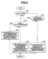
- variable valve overlap control attained by virtue of the variable valve timing control device 13, are described hereunder in accordance with each of the flow charts shown in Figs. 4, 5 and 6.
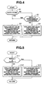
- a first valve overlap control routine which is used for switching the valve overlap and for controlling the timing of switching between the combustion modes.
- the target valve overlap tOVL may be set or retrieved on the basis of the engine operating condition, such as the engine speed Ne and the engine load, from a predetermined target valve overlap versus engine operating condition characteristic map for use in the homogeneous combustion mode.
- the use of the map-retrieved value defined as a variable based on the engine operating condition (engine speed and load), is superior to the use of the predetermined low set value being a fixed value irrespective of engine speed and load.
- the routine flows to step S4.
- the target valve overlap tOVL may be set or retrieved on the basis of the engine operating condition, such as the engine speed Ne and the engine load, from a predetermined target valve overlap versus engine operating condition characteristic map for use in the stratified combustion mode.
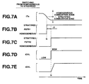
- the switch timing of the target valve overlap tOVL and the actual valve overlap rOVL in the switching mode from homogeneous to stratified combustion mode, obtained by the first overlap control routine shown in Fig. 4, is hereinbelow explained by reference to the timing charts shown in Figs. 7A to 7E.
- the target valve overlap tOVL is maintained at a low level (a predetermined low valve overlap suitable for homogeneous combustion) for a brief time duration from a target combustion mode switch timing t 1 to an actual combustion mode switch timing t 2 .
- the first overlap control routine effectively prevents the actual overlap rOVL from being shifted from low to high. This prevents deterioration in combustion.
- the switch timing of the target valve overlap tOVL (or the actual valve overlap rOVL) in the switching mode from stratified-to-homogeneous combustion mode, is explained by reference to the timing charts shown in Figs. 8A to 8E.
- the target valve overlap tOVL is quickly instantaneously shifted from high to low at the target combustion mode switch timing t 1 (FSTR1 1 ⁇ 0) earlier than the actual combustion mode switch timing t 2 (FSTR2 1 ⁇ 0).
- the target valve overlap tOVL shifts from high to low (see the flow from step S1 to step S3) instantaneously at the time (the switch point t 1 ) when the condition of FSTR1 # FSTR2 has been satisfied.
- the actual valve overlap rOVL tends to shift from high to low with a slight time lag, resulting from the response delay in valve-timing adjustment of the variable valve timing control device 13.
- the actual valve overlap rOVL never remains high during early stages (the starting period) of homogeneous combustion mode, irrespective of the response delay in valve-timing adjustment (i.e., the response delay in valve-overlap adjustment).
- the actual valve overlap rOVL is rapidly reduced to low substantially at the actual combustion mode switch timing t 2 , owing to the earlier switch timing (t 1 ). This prevents deterioration in combustion.
- FIG. 5 there is shown a second valve overlap control routine.
- step S11 a test is made to determine whether the target combustion mode switch flag FSTR1 is set at "1" (stratified combustion mode), and additionally the actual combustion mode switch flag FSTR2 is set at "1" (stratified combustion mode).
- the target valve overlap tOVL is set at a comparatively low set value suitable for the homogeneous combustion mode.
- the target valve overlap tOVL may be set or retrieved on the basis of the engine operating condition, such as the engine speed Ne and the engine load, from a predetermined target valve overlap versus engine operating condition characteristic map for use in the homogeneous combustion mode.
- the target valve overlap tOVL is set at a comparatively high set value suitable for the stratified combustion mode.
- the target valve overlap tOVL may be set or retrieved on the basis of the engine operating condition, such as the engine speed Ne and the engine load, from a predetermined target valve overlap versus engine operating condition characteristic map for use in the stratified combustion mode.
- the actual valve overlap can be set at a predetermined low valve overlap suitable for homogeneous combustion.
- the second valve overlap control routine of Fig. 5 is simplified as compared to the first valve overlap control routine of Fig. 4, the second routine of Fig. 5 produces the same effect as the first routine of Fig. 4. That is, the second routine can perform the valve overlap control indicated by the timing charts shown in Figs. 7A - 7E in case of occurrence of homogeneous-to-stratified combustion mode switching requirement, and perform the valve overlap control indicated by the timing charts shown in Fig. 8A - 8E in case of occurrence of stratified-to-homogeneous combustion mode switching requirement.
- ⁇ t t 2 - t 1
- the actual overlap rOVL can be switched to high at the later valve overlap switch timing t 2 in comparison with the first switch point t 1 .
- the actual overlap rOVL can be switched quickly to low at the earlier valve overlap switch timing t 1 .
- step S22 a test is made to determine whether the homogeneous lean combustion flag FLEAN is set at "1". In other words, in step S23, a check is made to determine whether the actual combustion mode is the homogeneous lean combustion mode.
- the target valve overlap tOVL may be set or retrieved on the basis of the engine operating condition, such as the engine speed Ne and the engine load, from a predetermined target valve overlap versus engine operating condition characteristic map for use in the homogeneous lean combustion mode.
- the target valve overlap tOVL may be set or retrieved on the basis of the engine operating condition, such as the engine speed Ne and the engine load, from a predetermined target valve overlap versus engine operating condition characteristic map for use in the homogeneous stoichiometric combustion mode.
- the target valve overlap tOVL may be set or retrieved on the basis of the engine operating condition, such as the engine speed Ne and the engine load, from a predetermined target valve overlap versus engine operating condition characteristic map for use in the stratified combustion mode.
- the previously-noted three characteristic maps are different from each other.
- the switch timing of the valve overlap in the switching mode from homogeneous-stoichiometric via homogeneous-lean to ultra-lean-stratified combustion mode, obtained by the third overlap control routine shown in Fig. 6, is hereinbelow explained by reference to the timing charts shown in Figs. 9A to 9G.
- the target overlap tOVL is, first of all, switched from a low level (a predetermined low valve overlap suitable for homogeneous stoichiometric combustion) to a medium level (a predetermined medium valve overlap suitable for homogeneous lean combustion), at the time to when the homogeneous lean combustion flag FLEAN is switched from "0" to "1".
- the third overlap control routine effectively prevents the actual overlap rOVL from being shifted from medium to high. This prevents deterioration in combustion.
- the target overlap tOVL is quickly instantaneously switched from high to medium at the time t 1 (FSTR1 1 ⁇ 0) of ultra-lean-stratified to homogeneous-lean combustion mode switching requirement earlier than the time to (FLEAN 1 ⁇ 0) of homogeneous-lean to homogeneous-stoichiometric combustion mode switching requirement.
- the actual valve overlap rOVL tends to shift from high to medium with a slight time lag, resulting from the response delay in valve-timing adjustment of the variable valve timing control device 13.
- the actual valve overlap rOVL never remains high during early stages of homogeneous-lean combustion mode, irrespective of the response delay in valve-timing adjustment (i.e., the response delay in valve-overlap adjustment).
- the actual valve overlap rOVL is rapidly reduced to medium just before the second switch point t 0 , owing to the earlier valve overlap switch timing (t 1 ). This prevents deterioration in combustion.
- the target overlap tOVL is quickly instantaneously switched from medium to low at the second switch timing to (FLEAN 1 ⁇ 0) earlier than the actual combustion mode switch timing t 2 (FSTR2 1 ⁇ 0).
- the actual valve overlap rOVL tends to shift from medium to low with a slight time lag, resulting from the response delay in valve-timing adjustment of the variable valve timing control device 13.
- the actual valve overlap rOVL never remains medium during early stages of homogeneous-stoichiometric combustion mode, irrespective of the response delay in valve-timing adjustment (i.e., the response delay in valve-overlap adjustment).
- the actual valve overlap rOVL is rapidly reduced to low just before the actual combustion mode switch timing t 2 , owing to the earlier valve overlap switch timing (t 0 ). This prevents deterioration in combustion.
- the switch timing from high to medium valve overlap is identical to the first switch timing (the first switch point) t 1 of occurrence of switching requirement between the ultra-lean-stratified combustion mode and the homogeneous-lean combustion mode.
- the switch timing from medium to low valve overlap is identical to the second switch timing (the second switch point) to of occurrence of switching requirement (FLEAN 1 ⁇ 0) from the homogeneous-lean combustion mode to the homogeneous-stoichiometric combustion mode.
- the overlap switch timing from low to medium is also identical to the second switch timing (the second switch point) to of occurrence of switching requirement (FLEAN 0 ⁇ 1) from the homogeneous-stoichiometric combustion mode to the homogeneous-lean combustion mode.
- the actual overlap rOVL can be switched quickly to medium at the earlier valve overlap switch timing t 1 .
- the actual overlap rOVL can be switched quickly to low at the earlier valve overlap switch timing t 0 .
Landscapes
- Engineering & Computer Science (AREA)
- Mechanical Engineering (AREA)
- General Engineering & Computer Science (AREA)
- Chemical & Material Sciences (AREA)
- Combustion & Propulsion (AREA)
- Electrical Control Of Air Or Fuel Supplied To Internal-Combustion Engine (AREA)
- Output Control And Ontrol Of Special Type Engine (AREA)
- Combustion Methods Of Internal-Combustion Engines (AREA)
- Combined Controls Of Internal Combustion Engines (AREA)
Claims (6)
- Motor vom Direkt- In- Zylinder- Einspritztyp mit Funkenzündung, der zumindest einen homogenen Verbrennungsmodus verwendet, wo eine frühe Kraftstoffeinspritzung während eines Einlasshubes ein homogenes Luft- Kraftstoff- Gemisch erzeugt und einen geschichteten Verbrennungsmodus verwendet, wo eine späte Kraftstoffeinspritzung während des Verdichtungshubes ein geschichtetes Luft-Kraftstoff- Gemisch erzeugt, aufweisend:eine veränderbare Ventilüberlappungsvorrichtung (13), montiert an zumindest einem von den Einlass- oder Auslassventilen (11, 12) für ein veränderbares Einstellen einer Ventilüberlappung, während der offene Zeitdauer der Einlass- und Auslassventile (11, 12) sich überlappen; und eine Steuerungseinheit (20), verbunden mit einem Kraftstoffeinspritzer (5) zum Schalten zwischen dem homogenen Verbrennungsmodus und dem geschichteten Verbrennungsmodus, und verbunden mit der veränderbaren Ventilüberlappungsvorrichtung (13) zum Schalten zwischen einer ersten Ventilüberlappung, geeignet für den homogenen Verbrennungsmodus und einer zweiten Ventilüberlappung, geeignet für den geschichteten Verbrennungsmodus,dadurch gekennzeichnet, dass die Steuerungseinheit (20) einen Überlappungsschaltzeitpunkt- Steuerungsabschnitt aufweist, der in der Lage ist, den ersten Zeitpunkt (t2) des Schaltens von der ersten Ventilüberlappung zu der zweiten Ventilüberlappung zu verzögern und einen zweiten Zeitpunkt (t1) des Schaltens von der zweiten Ventilüberlappung zu der ersten Ventilüberlappung vorzuverstellen, wobei die Steuerungseinheit (20) aufweist einen Ziel- Verbrennungsmodus-Festlegungsabschnitt (102) zum Festlegen, auf der Grundlage eines Motorbetriebszustandes, eines Ziel- Verbrennungsmodus auf entweder dem homogenen Verbrennungsmodus oder dem geschichteten Verbrennungsmodus, und einen Verbrennungsmodus Schaltzeitpunkt- Entscheidungsabschnitt (105), um einen tatsächlichen Verbrennungsmodus- Schaltzeitpunkt (t2) festzulegen, bei dem der Verbrennungsmodus tatsächlich einem von dem homogenen Verbrennungsmodus oder dem geschichteten Verbrennungsmodus zu dem anderen geschaltet wird, wobei der tatsächliche Verbrennungsmodus- Schaltzeitpunkt durch eine Verzögerungszeit (Δt) von einem Ziel- Verbrennungsmodus- Schaltzeitpunkt (t1) auf der Grundlage des Motorbetriebszustandes verzögert ist, und wobei der Überlappungsschaltzeitpunkt- Steuerungsabschnitt von der ersten Ventilüberlappung zu der zweiten Ventilüberlappung umschaltet zu dem ersten Zeitpunkt, der dem tatsächlichen Verbrennungsmodus- Schaltzeitpunkt (t2) entspricht, während des Schaltens von dem homogenen Verbrennungsmodus zu dem geschichteten Verbrennungsmodus, und von der zweiten Ventilüberlappung zu der ersten Ventilüberlappung zu dem zweiten Zeitpunkt schaltet, der dem Ziel- Verbrennungsmodus- Schaltzeitpunkt (t1) entspricht, während des Schaltens von dem geschichteten Verbrennungsmodus zu dem homogenen Verbrennungsmodus.
- Motor vom Direkt- In- Zylinder- Einspritztyp mit Funkenzündung nach Anspruch 1, dadurch gekennzeichnet, dass die Steuerungseinheit (20) aufweist einen Basis-Äquivalentverhältnis- Festlegungsabschnitt (103) zum Festlegen eines Basisäquivalentverhältnisses (TFBYAO) auf der Grundlage des Ziel- Verbrennungsmodus, einen Ziel- Äquivalentverhältnis- Berechnungsabschnitt (104) zum Berechnen eines Ziel- Äquivalentverhältnis (TFBYA) durch Herbeiführen einer vorbestimmten Phasenverzögerungsbearbeitung zu dem Basis- Äquivalentverhältnis (TFBYAO), und einen Verbrennungsmodus- Schaltzeitpunkt- Entscheidungsabschnitt (105) zum Vergleichen des Ziel- Äquivalentverhältnisses (TFBYA) zu einem vorbestimmten Grenzwert aufweist und einen tatsächlichen Verbrennungsmodus-Schaltzeitpunktes (t2) auf eine Zeit festlegt, wenn das Ziel- Äquivalentverhältnisses (TFBYA) den vorbestimmten Grenzwert überschreitet.
- Motor vom In- Zylinder- Einspritztyp mit Funkenzündung nach Anspruch 2, dadurch gekennzeichnet, dass die vorbestimmte Phasenverzögerungsbearbeitung zu dem Basis- Äquivalentverhältnis (TFBYAO) eine gewichtete Mittelwertverarbeitung ist, definiert durch TFBYA = M X TFBYAO + (1-M) x TFBYA, wo M einen Gewichtungsfaktor des gewichteten Mittelwertes bezeichnet.
- Motor vom Direkt- In- Zylinder- Einspritztyp mit Funkenzündung nach Anspruch 1, dadurch gekennzeichnet, dass der homogene Verbrennungsmodus außerdem in einen homogenen stöchiometrischen Verbrennungsmodus und einen homogenen mageren Verbrennungsmodus geteilt ist und die Steuerungseinheit (20) mit dem Kraftstoffeinspritzer (5) verbunden ist, so dass der Verbrennungsmodus zwischen dem homogenen stöchiometrischen Verbrennungsmodus, dem homogenen mageren Verbrennungsmodus und dem geschichteten Verbrennungsmodus schaltbar ist, und mit der Ventilüberlappungsvorrichtung (13)verbunden ist, so dass die Ventilüberlappung zwischen der ersten Ventilüberlappung, geeignet für den homogenen stöchiometrischen Verbrennungsmodus, einer zweiten Ventilüberlappung, geeignet für den geschichteten Verbrennungsmodus, und einer dritten Ventilüberlappung, geeignet für den homogenen mageren Verbrennungsmodus schaltbar ist.
- Motor vom Direkt- In- Zylinder- Einspritztyp mit Funkenzündung nach Anspruch 4, dadurch gekennzeichnet, dass die erste Ventilüberlappung ein niedrig festgelegter Wert ist, die zweite Ventilüberlappung ein hoch festgelegter Wert ist und die dritte Ventilüberlappung ein mittlerer festgelegter Wert ist.
- Motor vom Direkt- In- Zylinder- Einspritztyp mit Funkenzündung nach Anspruch 4, dadurch gekennzeichnet, dass die erste Ventilüberlappung ein niedriger Wert ist, abgeleitet aus einem vorbestimmten Kennlinienplan für den homogenen stöchiometrischen Verbrennungsmodus, die zweite Ventilüberlappung ein hoher Wert ist, abgeleitet von einem vorbestimmten Kennlinienplan für den geschichteten Verbrennungsmodus, und die dritte Ventilüberlappung ein mittlerer Wert ist, abgeleitet von einem vorbestimmten Kennlinienplan für den homogenen mageren Verbrennungsmodus, und der vorbestimmte Kennlinienplan für den homogenen stöchiometrischen Verbrennungsmodus , der vorbestimmte Kennlinienplan für den homogenen mageren Verbrennungsmodus und der vorbestimmte Kennlinienplan für den geschichteten Verbrennungsmodus voneinander verschieden sind.
Applications Claiming Priority (3)
| Application Number | Priority Date | Filing Date | Title |
|---|---|---|---|
| JP19669597A JP3677954B2 (ja) | 1997-07-23 | 1997-07-23 | 内燃機関の制御装置 |
| JP19669597 | 1997-07-23 | ||
| JP196695/97 | 1997-07-23 |
Publications (3)
| Publication Number | Publication Date |
|---|---|
| EP0893596A2 EP0893596A2 (de) | 1999-01-27 |
| EP0893596A3 EP0893596A3 (de) | 2000-07-05 |
| EP0893596B1 true EP0893596B1 (de) | 2006-10-18 |
Family
ID=16362061
Family Applications (1)
| Application Number | Title | Priority Date | Filing Date |
|---|---|---|---|
| EP98113426A Expired - Lifetime EP0893596B1 (de) | 1997-07-23 | 1998-07-17 | Fremdgezündete Brennkraftmaschine mit Einspritzung in den Zylinder |
Country Status (5)
| Country | Link |
|---|---|
| US (1) | US5967114A (de) |
| EP (1) | EP0893596B1 (de) |
| JP (1) | JP3677954B2 (de) |
| KR (1) | KR100284793B1 (de) |
| DE (1) | DE69836173T2 (de) |
Families Citing this family (37)
| Publication number | Priority date | Publication date | Assignee | Title |
|---|---|---|---|---|
| DE19810466C2 (de) * | 1998-03-11 | 1999-12-30 | Daimler Chrysler Ag | Verfahren zum Betrieb eines Ottomotors mit Direkteinspritzung |
| US6314939B1 (en) * | 1999-03-11 | 2001-11-13 | Outboard Marine Corporation | Methods and apparatus for controlling engine operation |
| JP2000282848A (ja) * | 1999-03-30 | 2000-10-10 | Nissan Motor Co Ltd | 内燃機関の排気浄化装置 |
| JP2000356143A (ja) * | 1999-06-14 | 2000-12-26 | Toyota Motor Corp | 内燃機関の燃焼制御装置 |
| JP3332011B2 (ja) * | 1999-06-22 | 2002-10-07 | トヨタ自動車株式会社 | 内燃機関の制御装置 |
| US7398762B2 (en) * | 2001-12-18 | 2008-07-15 | Ford Global Technologies, Llc | Vehicle control system |
| US6560527B1 (en) * | 1999-10-18 | 2003-05-06 | Ford Global Technologies, Inc. | Speed control method |
| US6978764B1 (en) | 1999-10-18 | 2005-12-27 | Ford Global Technologies, Inc. | Control method for a vehicle having an engine |
| US6712041B1 (en) | 1999-10-18 | 2004-03-30 | Ford Global Technologies, Inc. | Engine method |
| US6470869B1 (en) * | 1999-10-18 | 2002-10-29 | Ford Global Technologies, Inc. | Direct injection variable valve timing engine control system and method |
| JP3805574B2 (ja) * | 1999-09-06 | 2006-08-02 | 本田技研工業株式会社 | 内燃機関の制御装置 |
| US6425367B1 (en) * | 1999-09-17 | 2002-07-30 | Nissan Motor Co., Ltd. | Compression self-ignition gasoline internal combustion engine |
| US7299786B2 (en) | 2004-02-05 | 2007-11-27 | Ford Global Technologies Llc | Vehicle control system |
| US6321714B1 (en) | 2000-01-13 | 2001-11-27 | Ford Global Technologies, Inc. | Hybrid operating mode for DISI engines |
| DE10122775A1 (de) * | 2000-05-18 | 2001-11-22 | Ford Global Tech Inc | Hybrider Motor und Verfahren zu dessen Taktsteuerung |
| US6405706B1 (en) * | 2000-08-02 | 2002-06-18 | Ford Global Tech., Inc. | System and method for mixture preparation control of an internal combustion engine |
| JP2002242716A (ja) * | 2001-02-21 | 2002-08-28 | Hitachi Ltd | 筒内噴射エンジンの制御装置 |
| JP2002349239A (ja) * | 2001-05-24 | 2002-12-04 | Isuzu Motors Ltd | ディーゼルエンジンの排気浄化装置 |
| DE10148871C1 (de) * | 2001-10-04 | 2003-06-12 | Bosch Gmbh Robert | Verfahren zum Betreiben einer Brennkraftmaschine, Steuergerät für eine Brennkraftmaschine und Brennkraftmaschine |
| EP1319822B9 (de) * | 2001-12-14 | 2007-12-26 | Ford Global Technologies, LLC | Brennkraftmaschine mit Direkteinspritzung |
| US6840237B2 (en) * | 2002-12-30 | 2005-01-11 | Ford Global Technologies, Llc | Method for auto-ignition operation and computer readable storage device |
| US7013852B2 (en) * | 2003-03-06 | 2006-03-21 | Denso Corporation | Control apparatus for an internal combustion engine |
| JP4172319B2 (ja) * | 2003-04-30 | 2008-10-29 | 三菱自動車エンジニアリング株式会社 | エンジンの可変バルブタイミング制御装置 |
| JP2006336511A (ja) * | 2005-05-31 | 2006-12-14 | Hitachi Ltd | 内燃機関の制御装置 |
| DE102005040107B3 (de) * | 2005-08-24 | 2007-05-31 | Siemens Ag | Kombiniertes PET-MRT-Gerät und Verfahren zur gleichzeitigen Aufnahme von PET-Bildern und MR-Bildern |
| CN101321939B (zh) * | 2005-10-06 | 2012-06-13 | 通用汽车环球科技运作公司 | 直喷四冲程内燃发动机的操作方法和控制装置 |
| US20070175205A1 (en) * | 2006-01-31 | 2007-08-02 | Caterpillar Inc. | System for selective homogeneous charge compression ignition |
| DE102006027571A1 (de) * | 2006-06-14 | 2007-12-20 | Robert Bosch Gmbh | Verfahren zum Betrieb einer Brennkraftmaschine |
| FR2913065B1 (fr) | 2007-02-26 | 2012-10-19 | Inst Francais Du Petrole | Procede pour faciliter la vaporisation d'un carburant pour un moteur a combustion interne a injection directe de type diesel |
| DE112009005130B4 (de) * | 2009-08-07 | 2018-10-04 | Toyota Jidosha Kabushiki Kaisha | Brennkraftmaschine mit funkenzündung |
| DE102013014960A1 (de) * | 2013-09-10 | 2015-03-12 | Daimler Ag | Brennkraftmaschine und zugehöriges Betriebsverfahren |
| DE102013015010A1 (de) * | 2013-09-10 | 2015-03-26 | Daimler Ag | Brennkraftmaschine und zugehöriges Betriebsverfahren |
| DE102013014962A1 (de) * | 2013-09-10 | 2015-03-12 | Daimler Ag | Brennkraftmaschine und zugehöriges Betriebsverfahren |
| DE102013015012A1 (de) * | 2013-09-10 | 2015-03-12 | Daimler Ag | Brennkraftmaschine und zugehöriges Betriebsverfahren |
| DE102013015011A1 (de) * | 2013-09-10 | 2015-03-12 | Daimler Ag | Brennkraftmaschine und zugehöriges Betriebsverfahren |
| DE102018122963B4 (de) * | 2018-09-19 | 2025-01-09 | Keyou GmbH | Verfahren zum Betreiben einer Verbrennungskraftmaschine, insbesondere eines Gasmotors |
| US11698034B2 (en) * | 2021-04-13 | 2023-07-11 | GM Global Technology Operations LLC | Method of transient control for robust enrichment operation in low temperature combustion engine |
Family Cites Families (9)
| Publication number | Priority date | Publication date | Assignee | Title |
|---|---|---|---|---|
| US5088456A (en) * | 1990-01-30 | 1992-02-18 | Atsugi-Unisia Corporation | Valve timing control system to adjust phase relationship between maximum, intermediate, and minimum advance position |
| JPH04183945A (ja) * | 1990-11-19 | 1992-06-30 | Toyota Motor Corp | 筒内直接噴射式火花点火機関 |
| JP2872842B2 (ja) * | 1991-09-27 | 1999-03-24 | ヤマハ発動機株式会社 | 筒内噴射式2サイクルエンジンの燃焼制御装置 |
| JP3565912B2 (ja) * | 1994-09-28 | 2004-09-15 | 本田技研工業株式会社 | 内燃機関における動弁特性および空燃比の切換制御方法 |
| US5749346A (en) * | 1995-02-23 | 1998-05-12 | Hirel Holdings, Inc. | Electronic control unit for controlling an electronic injector fuel delivery system and method of controlling an electronic injector fuel delivery system |
| JP3152106B2 (ja) * | 1995-05-16 | 2001-04-03 | 三菱自動車工業株式会社 | 筒内噴射型火花点火式内燃エンジンの制御装置 |
| AUPN567195A0 (en) * | 1995-09-27 | 1995-10-19 | Orbital Engine Company (Australia) Proprietary Limited | Valve timing for four stroke internal combustion engines |
| JP3605221B2 (ja) * | 1996-03-19 | 2004-12-22 | 株式会社日立製作所 | 内燃機関の制御装置 |
| DE69722527T2 (de) * | 1996-08-09 | 2004-04-29 | Mitsubishi Jidosha Kogyo K.K. | Steuereinrichtung für Brennkraftmaschine mit Einspritzung in den Zylinder |
-
1997
- 1997-07-23 JP JP19669597A patent/JP3677954B2/ja not_active Expired - Lifetime
-
1998
- 1998-07-16 US US09/116,542 patent/US5967114A/en not_active Expired - Lifetime
- 1998-07-17 DE DE69836173T patent/DE69836173T2/de not_active Expired - Lifetime
- 1998-07-17 EP EP98113426A patent/EP0893596B1/de not_active Expired - Lifetime
- 1998-07-23 KR KR1019980029711A patent/KR100284793B1/ko not_active Expired - Lifetime
Also Published As
| Publication number | Publication date |
|---|---|
| KR100284793B1 (ko) | 2001-03-15 |
| JPH1136933A (ja) | 1999-02-09 |
| KR19990014118A (ko) | 1999-02-25 |
| JP3677954B2 (ja) | 2005-08-03 |
| DE69836173D1 (de) | 2006-11-30 |
| US5967114A (en) | 1999-10-19 |
| DE69836173T2 (de) | 2007-09-06 |
| EP0893596A2 (de) | 1999-01-27 |
| EP0893596A3 (de) | 2000-07-05 |
Similar Documents
| Publication | Publication Date | Title |
|---|---|---|
| EP0893596B1 (de) | Fremdgezündete Brennkraftmaschine mit Einspritzung in den Zylinder | |
| EP0922847B1 (de) | Vorrichtung zur Steuerung interner Verbrennungsmotoren | |
| US5979397A (en) | Control apparatus for direct injection spark ignition type internal combustion engine | |
| US6681741B2 (en) | Control apparatus for internal combustion engine | |
| JP2871615B2 (ja) | 内燃機関の排気浄化装置 | |
| US5988137A (en) | Controller of in-cylinder injection spark ignition internal combustion engine | |
| EP0824188B1 (de) | Steuereinrichtung für Brennkraftmaschine mit Einspritzung in den Zylinder | |
| JP3011070B2 (ja) | バルブタイミング連続可変機構付き内燃機関における吸入空気量検出装置 | |
| US6058905A (en) | Fuel injection control system for internal combustion engine | |
| US6470869B1 (en) | Direct injection variable valve timing engine control system and method | |
| JPH0941999A (ja) | 内燃機関の連続可変バルブタイミング制御装置 | |
| JP3616320B2 (ja) | 内燃機関の点火時期制御装置 | |
| US6655345B2 (en) | Valve timing controller, valve timing control method and engine control unit for internal combustion engine | |
| US6644275B2 (en) | Apparatus for controlling engine | |
| US6679206B2 (en) | Valve condition control system for an internal combustion engine and control method thereof | |
| JPH0972239A (ja) | エンジンの制御装置 | |
| AU2005317727B2 (en) | Valve characteristic control apparatus for internal combustion engine | |
| US11639699B2 (en) | Engine system and engine controlling method | |
| JP3620179B2 (ja) | 内燃機関の制御装置 | |
| JPH0972225A (ja) | 連続可変式バルブタイミング制御装置 | |
| US20230103525A1 (en) | Engine system and engine controlling method | |
| US20230108724A1 (en) | Engine controlling method and engine system | |
| JPH11218036A (ja) | 筒内直噴式内燃機関 | |
| JP2008095503A (ja) | 内燃機関 | |
| JP2005155428A (ja) | 内燃機関の制御装置 |
Legal Events
| Date | Code | Title | Description |
|---|---|---|---|
| PUAI | Public reference made under article 153(3) epc to a published international application that has entered the european phase |
Free format text: ORIGINAL CODE: 0009012 |
|
| 17P | Request for examination filed |
Effective date: 19980717 |
|
| AK | Designated contracting states |
Kind code of ref document: A2 Designated state(s): DE FR GB |
|
| AX | Request for extension of the european patent |
Free format text: AL;LT;LV;MK;RO;SI |
|
| PUAL | Search report despatched |
Free format text: ORIGINAL CODE: 0009013 |
|
| AK | Designated contracting states |
Kind code of ref document: A3 Designated state(s): AT BE CH CY DE DK ES FI FR GB GR IE IT LI LU MC NL PT SE |
|
| AX | Request for extension of the european patent |
Free format text: AL;LT;LV;MK;RO;SI |
|
| AKX | Designation fees paid |
Free format text: DE FR GB |
|
| 17Q | First examination report despatched |
Effective date: 20030523 |
|
| GRAP | Despatch of communication of intention to grant a patent |
Free format text: ORIGINAL CODE: EPIDOSNIGR1 |
|
| GRAS | Grant fee paid |
Free format text: ORIGINAL CODE: EPIDOSNIGR3 |
|
| GRAA | (expected) grant |
Free format text: ORIGINAL CODE: 0009210 |
|
| AK | Designated contracting states |
Kind code of ref document: B1 Designated state(s): DE FR GB |
|
| REG | Reference to a national code |
Ref country code: GB Ref legal event code: FG4D |
|
| REF | Corresponds to: |
Ref document number: 69836173 Country of ref document: DE Date of ref document: 20061130 Kind code of ref document: P |
|
| ET | Fr: translation filed | ||
| PLBE | No opposition filed within time limit |
Free format text: ORIGINAL CODE: 0009261 |
|
| STAA | Information on the status of an ep patent application or granted ep patent |
Free format text: STATUS: NO OPPOSITION FILED WITHIN TIME LIMIT |
|
| 26N | No opposition filed |
Effective date: 20070719 |
|
| REG | Reference to a national code |
Ref country code: FR Ref legal event code: PLFP Year of fee payment: 19 |
|
| REG | Reference to a national code |
Ref country code: FR Ref legal event code: PLFP Year of fee payment: 20 |
|
| PGFP | Annual fee paid to national office [announced via postgrant information from national office to epo] |
Ref country code: FR Payment date: 20170613 Year of fee payment: 20 |
|
| PGFP | Annual fee paid to national office [announced via postgrant information from national office to epo] |
Ref country code: DE Payment date: 20170711 Year of fee payment: 20 Ref country code: GB Payment date: 20170712 Year of fee payment: 20 |
|
| REG | Reference to a national code |
Ref country code: DE Ref legal event code: R071 Ref document number: 69836173 Country of ref document: DE |
|
| REG | Reference to a national code |
Ref country code: GB Ref legal event code: PE20 Expiry date: 20180716 |
|
| PG25 | Lapsed in a contracting state [announced via postgrant information from national office to epo] |
Ref country code: GB Free format text: LAPSE BECAUSE OF EXPIRATION OF PROTECTION Effective date: 20180716 |