EP0893609A2 - Ventilblock - Google Patents
Ventilblock Download PDFInfo
- Publication number
- EP0893609A2 EP0893609A2 EP98305705A EP98305705A EP0893609A2 EP 0893609 A2 EP0893609 A2 EP 0893609A2 EP 98305705 A EP98305705 A EP 98305705A EP 98305705 A EP98305705 A EP 98305705A EP 0893609 A2 EP0893609 A2 EP 0893609A2
- Authority
- EP
- European Patent Office
- Prior art keywords
- valve
- station
- passage
- front face
- extending
- Prior art date
- Legal status (The legal status is an assumption and is not a legal conclusion. Google has not performed a legal analysis and makes no representation as to the accuracy of the status listed.)
- Granted
Links
Images



Classifications
-
- F—MECHANICAL ENGINEERING; LIGHTING; HEATING; WEAPONS; BLASTING
- F15—FLUID-PRESSURE ACTUATORS; HYDRAULICS OR PNEUMATICS IN GENERAL
- F15B—SYSTEMS ACTING BY MEANS OF FLUIDS IN GENERAL; FLUID-PRESSURE ACTUATORS, e.g. SERVOMOTORS; DETAILS OF FLUID-PRESSURE SYSTEMS, NOT OTHERWISE PROVIDED FOR
- F15B13/00—Details of servomotor systems ; Valves for servomotor systems
- F15B13/02—Fluid distribution or supply devices characterised by their adaptation to the control of servomotors
- F15B13/06—Fluid distribution or supply devices characterised by their adaptation to the control of servomotors for use with two or more servomotors
- F15B13/08—Assemblies of units, each for the control of a single servomotor only
- F15B13/0803—Modular units
- F15B13/0807—Manifolds
- F15B13/0814—Monoblock manifolds
-
- C—CHEMISTRY; METALLURGY
- C03—GLASS; MINERAL OR SLAG WOOL
- C03B—MANUFACTURE, SHAPING, OR SUPPLEMENTARY PROCESSES
- C03B9/00—Blowing glass; Production of hollow glass articles
- C03B9/30—Details of blowing glass; Use of materials for the moulds
- C03B9/40—Gearing or controlling mechanisms specially adapted for glass-blowing machines
- C03B9/403—Hydraulic or pneumatic systems
- C03B9/406—Manifolds or regulating devices, e.g. valves
-
- F—MECHANICAL ENGINEERING; LIGHTING; HEATING; WEAPONS; BLASTING
- F15—FLUID-PRESSURE ACTUATORS; HYDRAULICS OR PNEUMATICS IN GENERAL
- F15B—SYSTEMS ACTING BY MEANS OF FLUIDS IN GENERAL; FLUID-PRESSURE ACTUATORS, e.g. SERVOMOTORS; DETAILS OF FLUID-PRESSURE SYSTEMS, NOT OTHERWISE PROVIDED FOR
- F15B13/00—Details of servomotor systems ; Valves for servomotor systems
- F15B13/02—Fluid distribution or supply devices characterised by their adaptation to the control of servomotors
- F15B13/06—Fluid distribution or supply devices characterised by their adaptation to the control of servomotors for use with two or more servomotors
- F15B13/08—Assemblies of units, each for the control of a single servomotor only
- F15B13/0803—Modular units
- F15B13/0821—Attachment or sealing of modular units to each other
-
- F—MECHANICAL ENGINEERING; LIGHTING; HEATING; WEAPONS; BLASTING
- F15—FLUID-PRESSURE ACTUATORS; HYDRAULICS OR PNEUMATICS IN GENERAL
- F15B—SYSTEMS ACTING BY MEANS OF FLUIDS IN GENERAL; FLUID-PRESSURE ACTUATORS, e.g. SERVOMOTORS; DETAILS OF FLUID-PRESSURE SYSTEMS, NOT OTHERWISE PROVIDED FOR
- F15B13/00—Details of servomotor systems ; Valves for servomotor systems
- F15B13/02—Fluid distribution or supply devices characterised by their adaptation to the control of servomotors
- F15B13/06—Fluid distribution or supply devices characterised by their adaptation to the control of servomotors for use with two or more servomotors
- F15B13/08—Assemblies of units, each for the control of a single servomotor only
- F15B13/0803—Modular units
- F15B13/0832—Modular valves
- F15B13/0835—Cartridge type valves
-
- F—MECHANICAL ENGINEERING; LIGHTING; HEATING; WEAPONS; BLASTING
- F15—FLUID-PRESSURE ACTUATORS; HYDRAULICS OR PNEUMATICS IN GENERAL
- F15B—SYSTEMS ACTING BY MEANS OF FLUIDS IN GENERAL; FLUID-PRESSURE ACTUATORS, e.g. SERVOMOTORS; DETAILS OF FLUID-PRESSURE SYSTEMS, NOT OTHERWISE PROVIDED FOR
- F15B13/00—Details of servomotor systems ; Valves for servomotor systems
- F15B13/02—Fluid distribution or supply devices characterised by their adaptation to the control of servomotors
- F15B13/06—Fluid distribution or supply devices characterised by their adaptation to the control of servomotors for use with two or more servomotors
- F15B13/08—Assemblies of units, each for the control of a single servomotor only
- F15B13/0803—Modular units
- F15B13/0878—Assembly of modular units
- F15B13/0882—Assembly of modular units using identical modular elements
-
- Y—GENERAL TAGGING OF NEW TECHNOLOGICAL DEVELOPMENTS; GENERAL TAGGING OF CROSS-SECTIONAL TECHNOLOGIES SPANNING OVER SEVERAL SECTIONS OF THE IPC; TECHNICAL SUBJECTS COVERED BY FORMER USPC CROSS-REFERENCE ART COLLECTIONS [XRACs] AND DIGESTS
- Y10—TECHNICAL SUBJECTS COVERED BY FORMER USPC
- Y10T—TECHNICAL SUBJECTS COVERED BY FORMER US CLASSIFICATION
- Y10T137/00—Fluid handling
- Y10T137/5109—Convertible
- Y10T137/5283—Units interchangeable between alternate locations
-
- Y—GENERAL TAGGING OF NEW TECHNOLOGICAL DEVELOPMENTS; GENERAL TAGGING OF CROSS-SECTIONAL TECHNOLOGIES SPANNING OVER SEVERAL SECTIONS OF THE IPC; TECHNICAL SUBJECTS COVERED BY FORMER USPC CROSS-REFERENCE ART COLLECTIONS [XRACs] AND DIGESTS
- Y10—TECHNICAL SUBJECTS COVERED BY FORMER USPC
- Y10T—TECHNICAL SUBJECTS COVERED BY FORMER US CLASSIFICATION
- Y10T137/00—Fluid handling
- Y10T137/8593—Systems
- Y10T137/87169—Supply and exhaust
- Y10T137/87193—Pilot-actuated
- Y10T137/87209—Electric
-
- Y—GENERAL TAGGING OF NEW TECHNOLOGICAL DEVELOPMENTS; GENERAL TAGGING OF CROSS-SECTIONAL TECHNOLOGIES SPANNING OVER SEVERAL SECTIONS OF THE IPC; TECHNICAL SUBJECTS COVERED BY FORMER USPC CROSS-REFERENCE ART COLLECTIONS [XRACs] AND DIGESTS
- Y10—TECHNICAL SUBJECTS COVERED BY FORMER USPC
- Y10T—TECHNICAL SUBJECTS COVERED BY FORMER US CLASSIFICATION
- Y10T137/00—Fluid handling
- Y10T137/8593—Systems
- Y10T137/877—With flow control means for branched passages
- Y10T137/87885—Sectional block structure
-
- Y—GENERAL TAGGING OF NEW TECHNOLOGICAL DEVELOPMENTS; GENERAL TAGGING OF CROSS-SECTIONAL TECHNOLOGIES SPANNING OVER SEVERAL SECTIONS OF THE IPC; TECHNICAL SUBJECTS COVERED BY FORMER USPC CROSS-REFERENCE ART COLLECTIONS [XRACs] AND DIGESTS
- Y10—TECHNICAL SUBJECTS COVERED BY FORMER USPC
- Y10T—TECHNICAL SUBJECTS COVERED BY FORMER US CLASSIFICATION
- Y10T137/00—Fluid handling
- Y10T137/8593—Systems
- Y10T137/87917—Flow path with serial valves and/or closures
- Y10T137/88022—One valve head provides seat for other head
- Y10T137/8803—Also carries head of other valve
Definitions
- This invention relates to valve blocks.
- Conventional glassware forming machines of the I.S. or individual section type comprise a plurality of sections, mechanically similar, operating out of phase with each other to produce a continuous stream of glass containers.
- Each section comprises a number of pneumatically operated mechanisms and each such mechanism comprises one or more pneumatic valves to control its operating sequence.
- Such pneumatic valves are normally controlled by solenoid operated pilot valves, which solenoid operated valves are controlled by a computerised control system for the machine.
- valve blocks which is mounted on the section, and significant constraints are placed upon the design of such valve blocks by the need to accommodate it in the space available in the width of one section and also by the need to make it reasonably accessible for repair and adjustment.
- a typical valve block is shown in US 3 918 489.
- This valve block comprises two castings secured together, one casting supporting the solenoid operated pilot valves in an array comprising two lines of such valves, and the other casting supporting the pneumatic valves associated with the pilot valves.
- the present invention provides a valve block comprising
- the present invention also provides a valve block comprising
- the present invention further provides a valve block comprising
- the valve block ( Figure 1) comprises a frame 2 which provides a plurality, namely 26, of valve stations 3 arranged in one or more, in fact in two, rows.
- the frame 2 is rectangular in shape and has a front face 4 and a rear face 6, which provide a front face and a rear face for each valve station.
- Figures 2 and 5 each show a transverse section through two valve stations.
- the frame 2 comprises extending lengthwise through the frame, two exhaust passages 8 and 10, a first, high, pressure passage 12 and a second, low, pressure passage 14.
- the exhaust passages 8 and 10 are each associated with the valve stations in separate rows; viewing Figure 2 the passage 8 extends lengthwise through all the valve stations in the upper row of valve stations, the passage 10 through all the valve stations in the lower row.
- the passages 12 and 14 each extend through both rows of valve stations.
- each valve station 3 in the lower row is the same so far as the frame 2 is concerned, while the construction of each valve station 3 in the upper row is effectively the same as those in the lower row, being mirror images.
- the precise configuration of parts associated with the frame at each valve station may differ, as will be explained later.
- the lower valve station 3 comprises an inlet passage 16 which extends directly from the rear face 6 to the front face 4 across the two pressure passages 12 and 14.
- a supply passage 18 also extends from the rear face 6 to the front face 4 of the station.
- a pilot air operated control valve 20 which comprises connecting air passages namely an inlet 22, a supply outlet 24 and an exhaust outlet 26.
- the valve 20 is mounted on the front face 4.
- the inlet 22 mates with a valve inlet passage 28 of the frame 2, the supply outlet 24 with the supply passage 18, and the exhaust outlet 26 with a valve exhaust passage 30 of the frame 2.
- the valve inlet passage 28 leads from the face 4 to a chamber 32 which is open to the inlet passage 16.
- the valve exhaust passage 30 leads from the face 4 to a chamber 34 which opens through an orifice 36 into the exhaust passage 10.
- the valve station 3 also comprises a control sleeve in the inlet passage 16 which determines whether the valve inlet passage 28 is connected to the high pressure passage 12 or the low pressure passage 14.
- the lower valve station 3 has a control sleeve 38 which connects the valve inlet passage 28 of that station to the high pressure passage 12, while the upper valve station 3 has a control sleeve 40 which connects the valve inlet passage 28 of that station to the lower pressure passage 14.
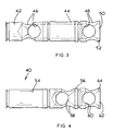
- the sleeve 38 which may be termed a high pressure sleeve, is shown in Figure 3. It is tubular in form and comprises a closed end 42 from which extends a cylindrical wall 44 to an open end 50.
- Four radially spaced entry ports 46 are provided in the wall 44 close to the closed end 42.
- Similar ports 48 are provided adjacent the open end 50 of the wall 44; the end 50 provides an annular end face 52.
- the sleeve 40 which may be termed a low pressure sleeve, is shown in Figure 4. It resembles the sleeve 38 being tubular in form, and comprises a thick closed end 54 from which a cylindrical wall 56 extends to an open end 62. Radially spaced entry ports 58 are provided in the wall 56, adjacent the closed end 54 and similar entry ports 60 are provided adjacent the open end 62 of the wall 56 which provides an annular end face 64.
- control sleeves are held in position in the frame 2 by stud arrangements 66 mounted on the front face 4 of the valve station 3, (best seen in Figure 5) which stud arrangements also provide throttle valves.
- Each stud arrangement 66 comprises a sleeve 68 comprising a narrower portion 70 and a larger portion 72.
- the larger portion 72 is provided with a screw thread which extends to a faceted head 74, and the larger portion 72 is screwed into an appropriate screw threaded bore in the front face 4 of the frame 2.
- a valve member 76 is mounted in the sleeve 68 and comprises a head 78 having a chamfered seating face 80 and mounted for sliding movement in the larger portion 72 of the sleeve 68, and a stem 82 which comprises a threaded portion 84 which engages in an internally threaded portion 86 of the narrower portion 70 of the sleeve 68.
- the valve members can thus be adjusted in the sleeve 68 by rotation of the members 76, achieved through use of a square head 88.
- the stud arrangement 66 may be used in one of three contexts.
- this serves to provide a throttle valve for controlling the passage of air from the chamber 34 through the orifice 36 into the exhaust passage 10.
- the chamfered face 80 is arranged opposite the orifice 36, and can be brought close to the orifice to restrict the flow of air from the valve 22 through the chamber 34 to exhaust, if required, by adjustment of the face 80 by rotation of the valve member 76.
- the next lowest stud arrangement viewing Figure 2 is associated with a high pressure control sleeve 38.
- the sleeve 68 of the stud arrangement is screwed into the frame 2 and the end face of the larger portion 72 of the sleeve 68 engages the annular end face 52 of the sleeve 38 to hold the sleeve in place in the inlet passage 16.
- the head 78 of the valve member 76 is dimensioned to be slidable within the cylindrical wall 44, and thus by adjustment of the position of the valve member 76, specifically of the axial position of the head 78 with respect to the entry ports 48, it is possible to control the rate of flow of air from the high pressure passage 12, through the control sleeve 38 in the inlet passage 16 and out through the ports 48 into the chamber 32.
- the next lowest stud arrangement viewing Figure 2 is associated with a low pressure control sleeve 40, and it can be seen that adjustment of the position of the valve member 76 will control the flow of low pressure air from the low pressure passage 14 through the entry ports 58, through the wall 56 of the control sleeve 40 and out through the ports 60 into a chamber equivalent to the chamber 32.
- the stud arrangements 66 also provide for the accurate location of the valves 20 at each valve station.
- Each valve 20 is provided with two through bores 90,92 each provided with enlarged end portions 100,102,104,106.
- the valve 20 is positioned at a valve station by being positioned on two adjacent stud arrangements 66, extending through the bores 90 and 92.
- the enlarged portions 100 and 104 fit over the faceted heads 74 of the sleeve 68, the bores 90,92 closely surround the sleeves 68, and the enlarged portions 102,104 accommodate nuts 108 which are secured on threaded end portions of the sleeves 68 to hold the valve 20 firmly in position.
- Each valve 20 is a pilot operated valve controlled by a solenoid operated pilot valve 110.
- each valve station 3 can be arranged to control high pressure air, by use of a sleeve 38 or low pressure air, by use of a sleeve 40. If, for example for [Plunger up operating air,] air at a pressure different from that of the main high pressure or low pressure air is required, such air may be provided to the valve block through a dedicated passage 112 (see Figure 5) and conveyed to the valve at the valve station through a simple sleeve 114 which does not connect to either the high pressure passage 12 or the low pressure passage 14.
- each valve station may be modified, by variation of the control sleeves, or repaired, by replacement of the valve 20, with access only to one face of the valve block.
- the stud arrangements 66 allow both the incoming air from the supply and the air passing to the exhaust from the valve 20 to be throttled; this throttling of air passing to exhaust allows conventional check valves to be dispensed with.
Landscapes
- Engineering & Computer Science (AREA)
- Mechanical Engineering (AREA)
- Physics & Mathematics (AREA)
- Fluid Mechanics (AREA)
- General Engineering & Computer Science (AREA)
- Chemical & Material Sciences (AREA)
- Manufacturing & Machinery (AREA)
- Materials Engineering (AREA)
- Organic Chemistry (AREA)
- Valve Housings (AREA)
- Multiple-Way Valves (AREA)
- Fluid-Pressure Circuits (AREA)
- Re-Forming, After-Treatment, Cutting And Transporting Of Glass Products (AREA)
Applications Claiming Priority (2)
| Application Number | Priority Date | Filing Date | Title |
|---|---|---|---|
| GB9715511 | 1997-07-24 | ||
| GBGB9715511.3A GB9715511D0 (en) | 1997-07-24 | 1997-07-24 | Valve block |
Publications (3)
| Publication Number | Publication Date |
|---|---|
| EP0893609A2 true EP0893609A2 (de) | 1999-01-27 |
| EP0893609A3 EP0893609A3 (de) | 1999-07-28 |
| EP0893609B1 EP0893609B1 (de) | 2004-02-11 |
Family
ID=10816318
Family Applications (1)
| Application Number | Title | Priority Date | Filing Date |
|---|---|---|---|
| EP98305705A Expired - Lifetime EP0893609B1 (de) | 1997-07-24 | 1998-07-17 | Ventilblock |
Country Status (6)
| Country | Link |
|---|---|
| US (1) | US6142185A (de) |
| EP (1) | EP0893609B1 (de) |
| JP (1) | JP4262325B2 (de) |
| CZ (1) | CZ298351B6 (de) |
| DE (1) | DE69821556T2 (de) |
| GB (1) | GB9715511D0 (de) |
Cited By (3)
| Publication number | Priority date | Publication date | Assignee | Title |
|---|---|---|---|---|
| WO2000069386A3 (en) * | 1999-05-13 | 2001-02-01 | Hill Rom Co Inc | Hydraulic control apparatus for a hospital bed |
| DE20013360U1 (de) * | 2000-08-03 | 2001-09-13 | Fa. Hermann Heye i.K., 31683 Obernkirchen | Ventilblock für eine Glasformmaschine |
| FR2806074A1 (fr) * | 2000-03-13 | 2001-09-14 | Emhart Glass Sa | Machine i.s. (a sections individuelles) |
Families Citing this family (5)
| Publication number | Priority date | Publication date | Assignee | Title |
|---|---|---|---|---|
| US6715320B2 (en) * | 2000-12-05 | 2004-04-06 | Vitro Corporativo, S.A. De C.V. | Fluid administration system for the operation of cylinder and piston assemblies |
| US6983623B2 (en) * | 2002-04-18 | 2006-01-10 | Sg Alternatives, Llc | Valve block assembly for I.S. glassware machine and modular pilot valve operated poppet valve assembly |
| DE102008048562A1 (de) * | 2008-09-23 | 2010-04-29 | Knorr-Bremse Systeme für Schienenfahrzeuge GmbH | Ventilanordnung zur Brems- sowie Zusatzgeräteansteuerung einer pneumatischen Bremsanlage eines Fahrzeuges |
| JP5748847B2 (ja) * | 2010-06-21 | 2015-07-15 | ロス エウロパ ゲゼルシャフト ミット ベシュレンクテル ハフツングROSS EUROPA GmbH | ガラス製造機に使用する弁ブロック用互換可能弁 |
| WO2016175775A1 (en) | 2015-04-29 | 2016-11-03 | Ross Operating Valve Company | Flow control mounting assembly for a valve |
Citations (1)
| Publication number | Priority date | Publication date | Assignee | Title |
|---|---|---|---|---|
| US3918489A (en) | 1972-06-23 | 1975-11-11 | Emhart Uk Ltd | Valve block |
Family Cites Families (13)
| Publication number | Priority date | Publication date | Assignee | Title |
|---|---|---|---|---|
| US3785389A (en) * | 1971-08-09 | 1974-01-15 | Process Systems | Fluid flow control system |
| US4082108A (en) * | 1976-07-19 | 1978-04-04 | Maul Technology Corporation | Valve block |
| US4382451A (en) * | 1979-02-16 | 1983-05-10 | Ball Corporation | Electronic valve assembly for glassware forming machinery |
| US4293004A (en) * | 1979-02-16 | 1981-10-06 | Ball Corporation | Electronic valve assembly for glassware forming machinery |
| MX152277A (es) * | 1980-12-16 | 1985-06-19 | Vitro Tec Fideicomiso | Mejoras en bloque de valvulas neumaticas de solenoide para maquinas de fabricacion de articulos de vidrio |
| FR2511786A1 (fr) * | 1981-08-21 | 1983-02-25 | Climax France Sa | Module regleur d'echappement pour un distributeur d'un fluide sous pression |
| US4446888A (en) * | 1981-12-15 | 1984-05-08 | Vitro-Tec Fideicomiso | Solenoid actuated valve block for glassware forming machines |
| IT1236747B (it) * | 1989-12-21 | 1993-03-31 | Blocco valvole elettropneumatico per macchine formatrici di oggetti in vetro cavo | |
| GB9203938D0 (en) * | 1992-02-25 | 1992-04-08 | Alexander Controls Ltd | Improvements relating to fluid flow control apparatus |
| GB2277083A (en) * | 1993-04-15 | 1994-10-19 | Emhart Glass Mach Invest | Connecting block |
| DE69411979T2 (de) * | 1993-04-15 | 1998-12-10 | Emhart Glass Machinery Investments Inc., Wilmington, Del. | Ventilblock für eine I.S.-Maschine |
| EP0667457B1 (de) * | 1994-02-15 | 1998-07-15 | Smc Corporation | Kolbenschieber-Wegeventil |
| JP3644732B2 (ja) * | 1995-10-02 | 2005-05-11 | Smc株式会社 | マニホールド形電磁弁 |
-
1997
- 1997-07-24 GB GBGB9715511.3A patent/GB9715511D0/en not_active Ceased
-
1998
- 1998-07-17 DE DE69821556T patent/DE69821556T2/de not_active Expired - Lifetime
- 1998-07-17 EP EP98305705A patent/EP0893609B1/de not_active Expired - Lifetime
- 1998-07-21 US US09/120,012 patent/US6142185A/en not_active Expired - Lifetime
- 1998-07-21 JP JP20474598A patent/JP4262325B2/ja not_active Expired - Fee Related
- 1998-07-22 CZ CZ0230298A patent/CZ298351B6/cs not_active IP Right Cessation
Patent Citations (1)
| Publication number | Priority date | Publication date | Assignee | Title |
|---|---|---|---|---|
| US3918489A (en) | 1972-06-23 | 1975-11-11 | Emhart Uk Ltd | Valve block |
Cited By (5)
| Publication number | Priority date | Publication date | Assignee | Title |
|---|---|---|---|---|
| WO2000069386A3 (en) * | 1999-05-13 | 2001-02-01 | Hill Rom Co Inc | Hydraulic control apparatus for a hospital bed |
| FR2806074A1 (fr) * | 2000-03-13 | 2001-09-14 | Emhart Glass Sa | Machine i.s. (a sections individuelles) |
| GB2360279A (en) * | 2000-03-13 | 2001-09-19 | Emhart Glass Sa | Blank mould valving system for I.S. glass moulding machine |
| GB2360279B (en) * | 2000-03-13 | 2004-03-10 | Emhart Glass Sa | I.S. Machine |
| DE20013360U1 (de) * | 2000-08-03 | 2001-09-13 | Fa. Hermann Heye i.K., 31683 Obernkirchen | Ventilblock für eine Glasformmaschine |
Also Published As
| Publication number | Publication date |
|---|---|
| US6142185A (en) | 2000-11-07 |
| DE69821556D1 (de) | 2004-03-18 |
| EP0893609B1 (de) | 2004-02-11 |
| JPH1193905A (ja) | 1999-04-06 |
| GB9715511D0 (en) | 1997-10-01 |
| JP4262325B2 (ja) | 2009-05-13 |
| CZ298351B6 (cs) | 2007-09-05 |
| DE69821556T2 (de) | 2004-08-05 |
| CZ230298A3 (cs) | 1999-03-17 |
| EP0893609A3 (de) | 1999-07-28 |
Similar Documents
| Publication | Publication Date | Title |
|---|---|---|
| EP0893609A2 (de) | Ventilblock | |
| EP1077349B1 (de) | Vorrichtung mit gestufter Brennstoffeinspritzung und Verfahren für Gasturbineneinspritzdüsen | |
| US3918489A (en) | Valve block | |
| US5810115A (en) | Pressure bypass accessory for a series progressive divider valve | |
| US4157149A (en) | Multiple nozzle fluid dispenser for complex fluid delivery patterns | |
| JP2008217829A (ja) | バイパス付き流体圧力調整装置モジュール | |
| KR20000006545A (ko) | 유체제어장치 | |
| US20020100509A1 (en) | Manifold and station for mounting steam/condensate responsive devices in a condensate return line | |
| US20050035225A1 (en) | Modular automatic spray gun manifold | |
| US5635227A (en) | Replaceable air cylinder unit and valve gate for injection molding machines | |
| EP0320233B1 (de) | Mehrventilzylinderkopf | |
| USRE31529E (en) | Electronic valve assembly for glassware forming machinery | |
| US4382451A (en) | Electronic valve assembly for glassware forming machinery | |
| EP0896178A2 (de) | Elektromagnetisch gesteuertes Druckluftventil | |
| MXPA98005949A (es) | Bloque de valvula | |
| EP0014942B1 (de) | Ventil, insbesondere für Glasbearbeitungsmaschine | |
| CZ296452B6 (cs) | Vzduchový ventil | |
| US7328593B2 (en) | Refrigerant valve arrangement | |
| JPH10176502A (ja) | 一体型蒸気弁 | |
| US6684777B2 (en) | Device for the control of blowing air, turner bar assembly, and printing machine | |
| JPH06161562A (ja) | 自動切換弁 | |
| EP0620194B1 (de) | Maschine zum Herstellen von Glasgegenständen | |
| US5673622A (en) | Device for wetting and cleaning cylinders in an offset rotary printing machine | |
| JPH0712261A (ja) | I.s.機械の弁ブロック組立体 | |
| WO2004094070A1 (en) | Liquid spray gun |
Legal Events
| Date | Code | Title | Description |
|---|---|---|---|
| PUAI | Public reference made under article 153(3) epc to a published international application that has entered the european phase |
Free format text: ORIGINAL CODE: 0009012 |
|
| AK | Designated contracting states |
Kind code of ref document: A2 Designated state(s): DE FR GB IT |
|
| AX | Request for extension of the european patent |
Free format text: AL;LT;LV;MK;RO;SI |
|
| PUAL | Search report despatched |
Free format text: ORIGINAL CODE: 0009013 |
|
| AK | Designated contracting states |
Kind code of ref document: A3 Designated state(s): AT BE CH CY DE DK ES FI FR GB GR IE IT LI LU MC NL PT SE |
|
| AX | Request for extension of the european patent |
Free format text: AL;LT;LV;MK;RO;SI |
|
| 17P | Request for examination filed |
Effective date: 20000121 |
|
| AKX | Designation fees paid |
Free format text: DE FR GB IT |
|
| RAP1 | Party data changed (applicant data changed or rights of an application transferred) |
Owner name: EMHART GLASS S.A. |
|
| 17Q | First examination report despatched |
Effective date: 20021022 |
|
| RAP1 | Party data changed (applicant data changed or rights of an application transferred) |
Owner name: EMHART GLASS S.A. |
|
| GRAP | Despatch of communication of intention to grant a patent |
Free format text: ORIGINAL CODE: EPIDOSNIGR1 |
|
| GRAS | Grant fee paid |
Free format text: ORIGINAL CODE: EPIDOSNIGR3 |
|
| GRAA | (expected) grant |
Free format text: ORIGINAL CODE: 0009210 |
|
| AK | Designated contracting states |
Kind code of ref document: B1 Designated state(s): DE FR GB IT |
|
| REG | Reference to a national code |
Ref country code: GB Ref legal event code: FG4D |
|
| REF | Corresponds to: |
Ref document number: 69821556 Country of ref document: DE Date of ref document: 20040318 Kind code of ref document: P |
|
| ET | Fr: translation filed | ||
| PLBE | No opposition filed within time limit |
Free format text: ORIGINAL CODE: 0009261 |
|
| STAA | Information on the status of an ep patent application or granted ep patent |
Free format text: STATUS: NO OPPOSITION FILED WITHIN TIME LIMIT |
|
| 26N | No opposition filed |
Effective date: 20041112 |
|
| PGFP | Annual fee paid to national office [announced via postgrant information from national office to epo] |
Ref country code: DE Payment date: 20130729 Year of fee payment: 16 |
|
| PGFP | Annual fee paid to national office [announced via postgrant information from national office to epo] |
Ref country code: GB Payment date: 20130729 Year of fee payment: 16 Ref country code: FR Payment date: 20130717 Year of fee payment: 16 |
|
| PGFP | Annual fee paid to national office [announced via postgrant information from national office to epo] |
Ref country code: IT Payment date: 20130725 Year of fee payment: 16 |
|
| REG | Reference to a national code |
Ref country code: DE Ref legal event code: R119 Ref document number: 69821556 Country of ref document: DE |
|
| GBPC | Gb: european patent ceased through non-payment of renewal fee |
Effective date: 20140717 |
|
| REG | Reference to a national code |
Ref country code: FR Ref legal event code: ST Effective date: 20150331 |
|
| PG25 | Lapsed in a contracting state [announced via postgrant information from national office to epo] |
Ref country code: IT Free format text: LAPSE BECAUSE OF NON-PAYMENT OF DUE FEES Effective date: 20140717 Ref country code: DE Free format text: LAPSE BECAUSE OF NON-PAYMENT OF DUE FEES Effective date: 20150203 |
|
| REG | Reference to a national code |
Ref country code: DE Ref legal event code: R119 Ref document number: 69821556 Country of ref document: DE Effective date: 20150203 |
|
| PG25 | Lapsed in a contracting state [announced via postgrant information from national office to epo] |
Ref country code: FR Free format text: LAPSE BECAUSE OF NON-PAYMENT OF DUE FEES Effective date: 20140731 Ref country code: GB Free format text: LAPSE BECAUSE OF NON-PAYMENT OF DUE FEES Effective date: 20140717 |