EP0893630A2 - Metallische Flachdichtung - Google Patents
Metallische Flachdichtung Download PDFInfo
- Publication number
- EP0893630A2 EP0893630A2 EP98109103A EP98109103A EP0893630A2 EP 0893630 A2 EP0893630 A2 EP 0893630A2 EP 98109103 A EP98109103 A EP 98109103A EP 98109103 A EP98109103 A EP 98109103A EP 0893630 A2 EP0893630 A2 EP 0893630A2
- Authority
- EP
- European Patent Office
- Prior art keywords
- bead
- flat gasket
- metallic flat
- support device
- gasket according
- Prior art date
- Legal status (The legal status is an assumption and is not a legal conclusion. Google has not performed a legal analysis and makes no representation as to the accuracy of the status listed.)
- Withdrawn
Links
- 229910052751 metal Inorganic materials 0.000 claims abstract description 6
- 239000002184 metal Substances 0.000 claims abstract description 6
- 239000011324 bead Substances 0.000 claims description 62
- 238000007789 sealing Methods 0.000 claims description 51
- 239000000463 material Substances 0.000 claims description 16
- 238000004519 manufacturing process Methods 0.000 claims description 4
- 239000007769 metal material Substances 0.000 claims description 3
- 239000012858 resilient material Substances 0.000 claims description 2
- 229920001971 elastomer Polymers 0.000 claims 1
- 239000000806 elastomer Substances 0.000 claims 1
- 238000002485 combustion reaction Methods 0.000 abstract description 21
- 239000010410 layer Substances 0.000 description 16
- 238000000576 coating method Methods 0.000 description 6
- 239000004033 plastic Substances 0.000 description 5
- 229920003023 plastic Polymers 0.000 description 5
- 230000006978 adaptation Effects 0.000 description 4
- 230000000694 effects Effects 0.000 description 4
- 230000008719 thickening Effects 0.000 description 4
- 238000010276 construction Methods 0.000 description 3
- 238000000034 method Methods 0.000 description 3
- XEEYBQQBJWHFJM-UHFFFAOYSA-N Iron Chemical compound [Fe] XEEYBQQBJWHFJM-UHFFFAOYSA-N 0.000 description 2
- 238000005452 bending Methods 0.000 description 2
- 239000011248 coating agent Substances 0.000 description 2
- 239000000567 combustion gas Substances 0.000 description 2
- XLYOFNOQVPJJNP-UHFFFAOYSA-N water Substances O XLYOFNOQVPJJNP-UHFFFAOYSA-N 0.000 description 2
- 239000004809 Teflon Substances 0.000 description 1
- 229920006362 Teflon® Polymers 0.000 description 1
- 238000009825 accumulation Methods 0.000 description 1
- 238000001816 cooling Methods 0.000 description 1
- 210000003746 feather Anatomy 0.000 description 1
- 239000000945 filler Substances 0.000 description 1
- 239000002737 fuel gas Substances 0.000 description 1
- 239000007789 gas Substances 0.000 description 1
- 238000009434 installation Methods 0.000 description 1
- 229910052742 iron Inorganic materials 0.000 description 1
- 239000007788 liquid Substances 0.000 description 1
- 230000013011 mating Effects 0.000 description 1
- 150000002739 metals Chemical class 0.000 description 1
- CWQXQMHSOZUFJS-UHFFFAOYSA-N molybdenum disulfide Chemical compound S=[Mo]=S CWQXQMHSOZUFJS-UHFFFAOYSA-N 0.000 description 1
- 230000002028 premature Effects 0.000 description 1
- 239000003566 sealing material Substances 0.000 description 1
- 238000007493 shaping process Methods 0.000 description 1
- 239000002356 single layer Substances 0.000 description 1
- 125000006850 spacer group Chemical group 0.000 description 1
- 229910001220 stainless steel Inorganic materials 0.000 description 1
- 239000010935 stainless steel Substances 0.000 description 1
- 230000003068 static effect Effects 0.000 description 1
- 238000012876 topography Methods 0.000 description 1
- 238000010792 warming Methods 0.000 description 1
Images

Classifications
-
- F—MECHANICAL ENGINEERING; LIGHTING; HEATING; WEAPONS; BLASTING
- F16—ENGINEERING ELEMENTS AND UNITS; GENERAL MEASURES FOR PRODUCING AND MAINTAINING EFFECTIVE FUNCTIONING OF MACHINES OR INSTALLATIONS; THERMAL INSULATION IN GENERAL
- F16J—PISTONS; CYLINDERS; SEALINGS
- F16J15/00—Sealings
- F16J15/02—Sealings between relatively-stationary surfaces
- F16J15/06—Sealings between relatively-stationary surfaces with solid packing compressed between sealing surfaces
- F16J15/08—Sealings between relatively-stationary surfaces with solid packing compressed between sealing surfaces with exclusively metal packing
- F16J15/0818—Flat gaskets
- F16J15/0825—Flat gaskets laminated
-
- F—MECHANICAL ENGINEERING; LIGHTING; HEATING; WEAPONS; BLASTING
- F16—ENGINEERING ELEMENTS AND UNITS; GENERAL MEASURES FOR PRODUCING AND MAINTAINING EFFECTIVE FUNCTIONING OF MACHINES OR INSTALLATIONS; THERMAL INSULATION IN GENERAL
- F16J—PISTONS; CYLINDERS; SEALINGS
- F16J15/00—Sealings
- F16J15/02—Sealings between relatively-stationary surfaces
- F16J15/06—Sealings between relatively-stationary surfaces with solid packing compressed between sealing surfaces
- F16J15/08—Sealings between relatively-stationary surfaces with solid packing compressed between sealing surfaces with exclusively metal packing
- F16J15/0818—Flat gaskets
- F16J2015/085—Flat gaskets without fold over
-
- F—MECHANICAL ENGINEERING; LIGHTING; HEATING; WEAPONS; BLASTING
- F16—ENGINEERING ELEMENTS AND UNITS; GENERAL MEASURES FOR PRODUCING AND MAINTAINING EFFECTIVE FUNCTIONING OF MACHINES OR INSTALLATIONS; THERMAL INSULATION IN GENERAL
- F16J—PISTONS; CYLINDERS; SEALINGS
- F16J15/00—Sealings
- F16J15/02—Sealings between relatively-stationary surfaces
- F16J15/06—Sealings between relatively-stationary surfaces with solid packing compressed between sealing surfaces
- F16J15/08—Sealings between relatively-stationary surfaces with solid packing compressed between sealing surfaces with exclusively metal packing
- F16J15/0818—Flat gaskets
- F16J2015/0856—Flat gaskets with a non-metallic coating or strip
Definitions
- the invention relates to a metallic flat gasket and especially a cylinder head gasket or exhaust gasket, in which the escape of hot combustion gases must be prevented over a long period of time.
- the distance between the cylinder head and the engine block is greater, the further you are from the fastening bolts or screws and are within them.
- the bolts are arranged close to the combustion chamber passages in order to ensure a good seal here, a kind of pillow-shaped or barrel-shaped vault is created between the engine block and the cylinder head gasket in the area of the combustion chamber passages, in which the bolts support the supporting columns or pillars of the vault are comparable.
- the spaces above the combustion chamber openings are not static, but the sealing gap changes with the combustion cycles.
- the edges of the seal stand out in a wedge shape from the bolts. These areas are also not completely rigid with an installed seal, but move up and down during operation. These movements are transmitted like a lever into the interior of the seal, the lever points lying approximately in the region of the connecting lines between adjacent bolt holes. Movements of the edge areas of the seal continue into the interior of the seal and make the sealing of the combustion chamber passages even more difficult.
- Cylinder head gaskets have proven a concept that follows to be referred to as a "two-line concept".
- the first sealing line is located directly in the Edge area of the seal around the respective combustion chamber opening.
- the second sealing line runs at a greater distance from the combustion chamber opening around the first sealing line.
- Seals that implement this concept are, for example from EP-A-0 230 804 and EP-A-0 306 766 known.
- the second sealing line are each in through formed at least one intermediate plate separate cover plates Beading present, the apexes on opposite Lay the sides of the intermediate plates.
- a stopper area at the combustion chamber edge of the seal formed as a first sealing line.
- the stopper area arises by folding over an intermediate sheet yourself (EP-A-0 306 766) or by folding one Intermediate plate around an arranged on the intermediate plate Spacer plate (EP-A-0 230 804).
- the stopper area prevents the combustion chamber openings the first sealing line that hot fuel gases act directly on the beads and the beads completely are flattened and thus lose their elasticity.
- this two-line seal is used achieved by the different sealing functions distributed on different sheet metal layers of a multi-layer seal become. This will make the seals complex and expensive.
- the object of the invention is to provide a metallic flat gasket which is simple in construction and easy and inexpensive to produce, but nevertheless ensures a reliable and permanent seal.
- the gasket according to the invention should be particularly suitable for use as a cylinder head gasket.
- the problem is solved with the flat gasket Claim 1. Further embodiments result from the Subclaims.
- the invention further relates to a method for the production of this seal according to claim 22.
- the invention thus relates to a metallic flat gasket which has at least one through opening which is completely enclosed by a bead. Radially within this bead, that is closer to the through opening, a support device is provided for the bead, which prevents the bead from completely flattening when the seal is installed.
- This support device is obtained in that the sealing edge surrounding the through opening is bent in the direction of the bead. The bending angle between the bent edge of the seal and the seal plane to the side of the seal opening is a maximum of 90 o .
- the support effect of the support device on the bead can be controlled in a targeted manner by adjusting the inclination.
- a particularly strong support is achieved at a bending angle of 90 o .
- the support device is essentially only plastically and no longer elastically deformable.
- the support device also performs a sealing function for the passage opening and prevents gas or liquid from the passage opening from acting directly on the bead located behind the support device.
- the bent sealing edge is expediently so long that it bears on both mating surfaces to be sealed when the seal is installed.
- the height of the support device preferably corresponds essentially to the height of the sealing gap to be sealed, while the support device is expediently longer at a bend angle of less than 90 o and here elastically adapts to the sealing gap.
- the edge area the support device is bent away from the bead.
- the edge area can be curved towards the Sealing plane be curved back.
- the support devices half corrugations are then comparable. Shaping and width of the edge area are appropriate according to the object to be sealed and the one found Sealing requirements.
- the configuration of the bead is also advantageous Conditions adjusted accordingly, so that between Support device and beading an optimal coordination is achieved.
- the setting of the springback properties the beading is carried out in a manner known per se, e.g. by varying the shape, bead width, height and Steepness and the choice of materials.
- the design the bead is not on special embodiments of the State of the art limited.
- the Beading be both round and square, where the latter variant is preferred when a high spring constant should be achieved.
- the bead basically designed both symmetrically and asymmetrically be.
- the bead can, for example, on your the flank facing the through hole rise more steeply than on the flank facing away from the through opening.
- the plastic and elastic properties the bead and / or the support device thereby influence that the space under the bulge of the bead and / or in the area between the support device and the bead wholly or partially with a plastically or elastically deformable Material is filled.
- Suitable filling materials are elastomeric plastics or metallic materials, especially soft metals such as soft iron. Even resilient materials like one or more Spirals, leaf or worm feather, which in the area of Bead curvature and / or between the bead and the support device be inserted so that they are the passage opening to be sealed circulate in whole or in part can be used.
- Beading and / or support device expediently in the circumferential direction profiled.
- the spring force expediently increases of support device and / or bead with increasing Distance from the bolt holes surrounding the bead to. This can be done in a manner known per se e.g. by a Increasing the bead height, reducing the bead width or increased steepness. Can accordingly the height and width as well as the slope of the support device change circumferentially.
- the width of the support device preferably in a range of 1.5 to 3 mm.
- Profiling in the circumferential direction can also be used for the filling materials be provided.
- a targeted adjustment of the deformability and support effect the support device is also due to a material accumulation possible in this area.
- the sheet thickness in the area of the support device and in particular in the immediately adjacent to the through opening Area can be enlarged. This will be useful by upsetting the sealing edge in the area of Through opening reached.
- the thickening is preferably generated so that it over the crease line towards the bead and expedient up to about the area of the beading foot continues.
- the deformation process be carried out at elevated temperature. A warming is recommended, for example, when using stainless steel spring sheet as sealing material.
- the material thickening in the area of the support device increases their rigidity and improves their support on the bead.
- beak-shaped widenings arise in the areas where the upsetting device hits the edge of the seal. This beaked Widenings are plastically deformable and ensure Installation state of the seal for particularly good adaptation to the counter surfaces to be sealed.
- the support device and the beading can be in immediate succession be arranged. However, they are preferred from one another spaced and by a substantially flat Section separated.
- the seals of the invention allow, despite their very simple construction through openings even under extreme Conditions such as those with combustion chamber openings are found in cylinder head gaskets, to seal effectively and permanently.
- the excellent Sealing effect is already achieved with seals that are designed as insert seals.
- the invention is however, not limited to single-layer seals, but in addition to the position, which comprises support device and bead, there may be one or more additional sealing layers be. For example, at least one corresponding to the first Layer shaped further layer parallel to the first layer these must be laminated on, leaving the metallic materials of the individual layers.
- all seals according to the invention can be intermediate or Include shim plates that serve the total thickness the seal the gap to be sealed (e.g. between Engine block and cylinder head).
- seals of the invention are also not on cylinder head gaskets limited, but are generally suitable for all areas in which flat seals are used for sealing of through openings are used.
- exhaust gaskets can be called exhaust gaskets.
- the seal of the invention at least on their all or part of the surface facing outwards coat.
- a coating is preferred used in cylinder head gaskets while at Exhaust gaskets are not essential.
- Suitable Coating materials are, for example, plastics or metallic coatings, as they are generally are common in the prior art. Be particularly useful coated those areas that are in contact with the counter surfaces to be sealed.
- Preferred coatings for example made of Teflon or molybdenum sulfide.
- surface textured Coatings can be used.
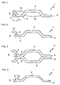
- FIG. 1 shows a partial cross section through a Cylinder head gasket 1 according to the invention, as shown in FIG. 5 is shown in partial plan view, in the area around a combustion chamber opening 6.
- the cylinder head gasket has Bolt holes 7, oil 8 and water passages 9 on.
- the seal 1 shown is an insert seal, which is only a metallic sealing layer 2 having.
- the combustion chamber openings 6 are each concentric surrounded by a support device 3 and a bead 4. For seals that are very close together Combustion chamber openings 6, the bead 4, if desired, in Area between two adjacent combustion chamber openings 6 converge in a single bead.
- the support device 3 is produced in that the Sealing edge in the area around the combustion chamber opening 6 with a Angle ⁇ is bent towards the bead 4. This remains between the bead 4 and the support device 3 a substantially flat section 5.
- the width b of the Support device 3 is in the case of a cylinder head gasket for example about 0.5 to 4 mm, in particular about 1.5 to 3 mm.
- To control the springback properties of support device 3 and bead 4 is in the area between support device 3 and bead flank and below the curvature of the bead 4 introduced filling material 10.
- the filling material 10 can be plastic or elastic deformable materials, act, for example around inserts made of elastomeric plastic or soft metal.
- FIGS. 2 to 4 show further embodiments the seal of the invention.
- a seal is shown again, which the in 5 may have the basic structure shown.
- the difference to the seal shown in Fig. 1 is the functional area, which has support device 3 and bead 4, here, however, designed as an insert ring 1 ', which is separate manufactured and subsequently in a corresponding Recess used in the seal according to the invention can be.
- the seal is the edge region 11 of the support device 3 curved back towards the sealing plane.
- the filler material inserts are missing.
- FIG. 3 shows a multi-layer seal according to the invention.
- the individual layers correspond to those in FIG. 2 shown.
- the second layer 2 ' is a mirror image below the first layer 2 arranged so that the beads 4 and 4 ' point away from each other.
- the sheet thickness of the sealing layer 2 in the area of the support device 3 is increased compared to the remaining area of the sealing layer 2.
- This can be done, for example, by upsetting the sealing edge from the through opening 6 in the direction of the bead 4.
- the sealing edge portion is first upset before the support means 3 by an angle ⁇ , here is 90 ° angled.
- the support device 3 is essentially only plastically deformable, but has hardly any elastic properties. Due to the upsetting process, beak-shaped deformations are formed on the edges of the support device 3, which are particularly easily plastically deformable and thus ensure a particularly good adaptation of the support device to the counter surface to be sealed.
- the thickening of the material in the area of the support device continues beyond the kink to approximately the area of the base of the bead 4, so that the kink is also stabilized by the thickening of the material.
- the seals according to the invention ensure despite their very simple construction an excellent and durable Sealing through openings where high demands are made be placed on a seal, like this at Combustion chamber openings of cylinder head gaskets is the case.
Landscapes
- Engineering & Computer Science (AREA)
- General Engineering & Computer Science (AREA)
- Mechanical Engineering (AREA)
- Gasket Seals (AREA)
Abstract
Description
Eine Schwierigkeit besteht weiter darin, daß es nicht möglich ist, eine Zylinderkopfdichtung so zwischen Motorblock und Zylinderkopf einzuspannen, daß eine vollkommen ebene Dichtungsfläche erhalten wird. Beim Befestigen des Zylinderkopfes auf dem Motorblock wird der Zylinderkopf im Bereich der Zylinderkopfschrauben nach unten, in Richtung auf den Motorblock gezogen. Dadurch entsteht in der Dichtung eine Topographie. Der Abstand des Zylinderkopfes vom Motorblock ist umso größer, je weiter man sich von den Befestigungsbolzen oder -schrauben entfernt und sich innerhalb dieser befindet. Wenn die Bolzen, wie üblich, nahe um die Brennraumdurchgänge angeordnet sind, um hier für eine gute Abdichtung zu sorgen, entsteht zwischen Motorblock und Zylinderkopfdichtung im Bereich der Brennraumdurchgänge eine Art von kissen- oder tonnenförmigem Gewölbe, bei dem die Bolzen den tragenden Säulen oder Pfeilern des Gewölbes vergleichbar sind. Im Unterschied zu einem Deckengewölbe sind die Räume oberhalb der Brennraumöffnungen jedoch nicht statisch, sondern der Dichtspalt ändert sich mit den Verbrennungszyklen. Die Dichtungsränder stehen dagegen von den Bolzen nach aussen hin keilförmig auf. Auch diese Bereiche sind bei einer eingebauten Dichtung nicht vollständig starr, sondern bewegen sich während des Betriebs auf und ab. Diese Bewegungen werden hebelartig in das Innere der Dichtung übertragen, wobei die Hebelpunkte in etwa im Bereich der Verbindungslinien zwischen benachbarten Bolzenlöchern liegen. Bewegungen der Dichtungsrandbereiche setzen sich also in das Innere der Dichtung fort und erschweren die Abdichtung der Brennraumdurchgänge zusätzlich.
Diese Abstützeinrichtung wird dadurch erhalten, daß der die Durchgangsöffnung umgebende Dichtungsrand in Richtung auf die Sicke hin aufgebogen wird. Der Biegewinkel zwischen aufgebogenem Dichtungsrand und Dichtungsebene zur Seite der Dichtungsöffnung hin beträgt dabei maximal 90o.
- Fig. 1 bis 4
- Teil-Querschnitte durch eine erfindungsgemäße Dichtungen und
- Fig. 5
- eine Teil-Draufsicht auf eine erfindungsgemäße Dichtung.
Claims (22)
- Metallische Flachdichtung (1), welche wenigstens eine Durchgangsöffnung (6) aufweist, die von einer Sicke (4) vollständig umschlossen ist, und in welcher in derselben Dichtungslage (2), die die Sicke (4) umfaßt, eine Abstützeinrichtung (3) für die Sicke (4) vorhanden ist,
dadurch gekennzeichnet,
daß die Abstützeinrichtung (3) durch eine Aufbiegung des die Durchgangsöffnung (6) umgebenden Dichtungsrandes in Richtung auf die Sickenwölbung mit einem Winkel (α) von maximal 90o gebildet wird. - Metallische Flachdichtung gemäß Anspruch 1,
dadurch gekennzeichnet,
daß die Dichtungslage (2) im Bereich der Abstützeinrichtung (3) gegenüber ihren restlichen Bereichen eine größere Dicke aufweist. - Metallische Flachdichtung gemäß Anspruch 2,
dadurch gekennzeichnet,
daß sich der verdickte Bereich der Dichtungslage (2) bis zum Fußpunkt der Sicke (4) erstreckt. - Metallische Flachdichtung gemäß einem der Ansprüche 1 bis 3,
dadurch gekennzeichnet,
daß der Dichtungsrand in einem Winkel (α) von 90o in Richtung auf die Sickenwölbung gebogen ist. - Metallische Flachdichtung gemäß einem der Ansprüche 1 bis 4,
dadurch gekennzeichnet,
daß der Randbereich (11) der Abstützeinrichtung (3) von der Sicke (4) weggebogen ist. - Metallische Flachdichtung gemäß Anspruch 5,
dadurch gekennzeichnet,
daß der Randbereich (11) der Abstützeinrichtung (3) bogenförmig gekrümmt ist. - Metallische Flachdichtung gemäß Anspruch 5,
dadurch gekennzeichnet,
daß der Randbereich (11) der Abstützeinrichtung (3) so abgewinkelt ist, daß er im wesentlichen parallel zur Dichtungsebene verläuft. - Metallische Flachdichtung gemäß einem der Ansprüche 1 bis 7,
dadurch gekennzeichnet,
daß sich zwischen Abstützeinrichtung (3) und Sicke (4) ein im wesentlichen ebener Abschnitt (5) befindet. - Metallische Flachdichtung gemäß einem der Ansprüche 1 bis 8,
dadurch gekennzeichnet,
daß die Sicke (4) eckig ist. - Metallische Flachdichtung gemäß einem der Ansprüche 1 bis 9,
dadurch gekennzeichnet,
daß die Sicke (4) asymmetrisch geformt ist. - Metallische Flachdichtung gemäß einem der Ansprüche 1 bis 10,
dadurch gekennzeichnet,
daß es sich um eine Mehrlagendichtung handelt. - Metallische Flachdichtung gemäß Anspruch 11,
dadurch gekennzeichnet,
daß parallel zu einer ersten Dichtungslage (2) mit Abstützeinrichtung (3) und Sicke (4) wenigstens eine weitere Dichtungslage mit Abstützeinrichtung und Sikke auflaminiert ist. - Metallische Flachdichtung gemäß Anspruch 12,
dadurch gekennzeichnet,
daß spiegelbildlich zu einer ersten Dichtungslage (2) mit Abstützeinrichtung (3) und Sicke (4) eine weitere Dichtungslage (2') mit Abstützeinrichtung (3') und Sicke (4') angeordnet ist. - Metallische Flachdichtung gemäß einem der Ansprüche 1 bis 13,
dadurch gekennzeichnet,
daß Abstützeinrichtung (3, 3') und/oder Sicke (4, 4') in Umfangsrichtung höhen- und/oder breitenprofiliert sind. - Metallische Flachdichtung gemäß einem der Ansprüche 1 bis 14,
dadurch gekennzeichnet,
daß der von der Sickenwölbung umschlossene Bereich der Sicke (4, 4') und/oder der von Sickenflanke und Abstützeinrichtung (3, 3') begrenzte Bereich mit einem verformbaren Material (10) ganz oder teilweise angefüllt ist. - Metallische Flachdichtung gemäß Anspruch 15,
dadurch gekennzeichnet,
daß das verformbare Material (10) ein Elastomer, ein metallisches Material oder ein federelastisches Material ist. - Metallische Flachdichtung gemäß einem der Ansprüche 1 bis 16,
dadurch gekennzeichnet,
daß zumindest ihre nach außen weisenden Oberflächen ganz oder teilweise beschichtet sind. - Metallische Flachdichtung gemäß Anspruch 17,
dadurch gekennzeichnet,
daß die Flächen, welche mit den abzudichtenden Gegenflächen in Kontakt kommen, beschichtet sind. - Metallische Flachdichtung gemäß einem der Ansprüche 1 bis 18,
dadurch gekennzeichnet,
daß der Funktionsbereich, welcher Abstützeinrichtung(en) (3, 3') und Sicke(n) (4, 4') umfaßt, als Einlageteil (1') und insbesondere als Einlagering ausgebildet ist, welcher in eine entsprechende Ausnehmung im restlichen Dichtungskörper eingesetzt ist. - Metallische Flachdichtung gemäß einem der Ansprüche 1 bis 19, nämlich Zylinderkopfdichtung oder Auspuffdichtung.
- Metallische Flachdichtung, nämlich Zylinderkopfdichtung gemäß Anspruch 20,
dadurch gekennzeichnet,
daß die Abstützeinrichtung (3, 3') eine Breite von 0,5 bis 4 mm und insbesondere von 1,5 bis 3 mm besitzt. - Verfahren zur Herstellung einer metallischen Flachdichtung (1) gemäß einem der Ansprüche 2 bis 21,
dadurch gekennzeichnet,
daß die Blechlage (2, 2') im Bereich der Abstützeinrichtung (3, 3') durch Anstauchen des Dichtungsrandes im Bereich der Durchgangsöffnung (6) vor dem Aufbiegen des Dichtungsrandes verdickt wird.
Applications Claiming Priority (2)
| Application Number | Priority Date | Filing Date | Title |
|---|---|---|---|
| DE19731489A DE19731489C2 (de) | 1997-07-22 | 1997-07-22 | Metallische Flachdichtung |
| DE19731489 | 1997-07-22 |
Publications (2)
| Publication Number | Publication Date |
|---|---|
| EP0893630A2 true EP0893630A2 (de) | 1999-01-27 |
| EP0893630A3 EP0893630A3 (de) | 1999-08-04 |
Family
ID=7836536
Family Applications (1)
| Application Number | Title | Priority Date | Filing Date |
|---|---|---|---|
| EP98109103A Withdrawn EP0893630A3 (de) | 1997-07-22 | 1998-05-19 | Metallische Flachdichtung |
Country Status (2)
| Country | Link |
|---|---|
| EP (1) | EP0893630A3 (de) |
| DE (1) | DE19731489C2 (de) |
Cited By (8)
| Publication number | Priority date | Publication date | Assignee | Title |
|---|---|---|---|---|
| EP0987474A3 (de) * | 1998-09-18 | 2000-10-25 | Taiho Kogyo Co., Ltd. | Zylinderkopfdichtung |
| WO2001096768A1 (de) * | 2000-06-15 | 2001-12-20 | Reinz-Dichtungs-Gmbh & Co. Kg | Flachdichtung und verfahren zu ihrer herstellung |
| EP1231415A2 (de) | 2001-02-09 | 2002-08-14 | Federal-Mogul Sealing Systems GmbH | Ein- oder mehrlagige Flachdichtung |
| EP1184608A3 (de) * | 2000-09-04 | 2003-10-29 | Nippon Gasket Co., Ltd. | Metallische Flachdichtung |
| EP1510734A3 (de) * | 2003-08-28 | 2005-03-16 | Carl Freudenberg KG | Dichtung mit flexiblem Stopper |
| JP2005172225A (ja) * | 2003-11-03 | 2005-06-30 | Freudenberg-Nok General Partnership | 可撓性ストッパを備えたシーリングガスケット |
| EP1462641A3 (de) * | 2003-03-26 | 2006-03-15 | Ishikawa Gasket Co. Ltd. | Metalldichtung |
| EP1679457A1 (de) * | 2000-06-15 | 2006-07-12 | Reinz-Dichtungs-Gmbh | Flachdichtung und Verfahren zu ihrer Herstellung |
Families Citing this family (1)
| Publication number | Priority date | Publication date | Assignee | Title |
|---|---|---|---|---|
| DE19939869A1 (de) * | 1999-08-23 | 2001-04-12 | Elringklinger Gmbh | Flachdichtung |
Citations (2)
| Publication number | Priority date | Publication date | Assignee | Title |
|---|---|---|---|---|
| EP0230804A2 (de) | 1985-12-27 | 1987-08-05 | Nihon Metal Gasket Kabushiki Kaisha | Metalldichtung |
| EP0306766A2 (de) | 1987-09-05 | 1989-03-15 | Nihon Metal Gasket Kabushiki Kaisha | Laminierte Metalldichtung |
Family Cites Families (8)
| Publication number | Priority date | Publication date | Assignee | Title |
|---|---|---|---|---|
| GB2045873B (en) * | 1978-11-14 | 1983-01-06 | Felt Products Mfg Co | Gaskets |
| JPS61255253A (ja) * | 1985-05-09 | 1986-11-12 | Nippon Metal Gasket Kk | 金属ガスケツト |
| JPH0622135Y2 (ja) * | 1986-01-13 | 1994-06-08 | 石川ガスケット株式会社 | 金属積叢形マニホ−ルドガスケット |
| JPH05602Y2 (de) * | 1988-06-30 | 1993-01-08 | ||
| DE4142600C2 (de) * | 1991-12-21 | 1995-07-13 | Elringklinger Gmbh | Zylinderkopfdichtung |
| DE19520695C1 (de) * | 1995-06-07 | 1996-07-04 | Elringklinger Gmbh | Metallische Zylinderkopfdichtung |
| JP3230966B2 (ja) * | 1995-10-09 | 2001-11-19 | 日本ガスケット株式会社 | 金属製ガスケット |
| DE69634031D1 (de) * | 1995-11-07 | 2005-01-20 | Nicholsons Aircraft Seals Ltd | Abdichtung |
-
1997
- 1997-07-22 DE DE19731489A patent/DE19731489C2/de not_active Expired - Fee Related
-
1998
- 1998-05-19 EP EP98109103A patent/EP0893630A3/de not_active Withdrawn
Patent Citations (2)
| Publication number | Priority date | Publication date | Assignee | Title |
|---|---|---|---|---|
| EP0230804A2 (de) | 1985-12-27 | 1987-08-05 | Nihon Metal Gasket Kabushiki Kaisha | Metalldichtung |
| EP0306766A2 (de) | 1987-09-05 | 1989-03-15 | Nihon Metal Gasket Kabushiki Kaisha | Laminierte Metalldichtung |
Cited By (15)
| Publication number | Priority date | Publication date | Assignee | Title |
|---|---|---|---|---|
| EP0987474A3 (de) * | 1998-09-18 | 2000-10-25 | Taiho Kogyo Co., Ltd. | Zylinderkopfdichtung |
| US7000924B2 (en) | 2000-06-15 | 2006-02-21 | Dana Corporation | Flat gasket and method for the production thereof |
| WO2001096768A1 (de) * | 2000-06-15 | 2001-12-20 | Reinz-Dichtungs-Gmbh & Co. Kg | Flachdichtung und verfahren zu ihrer herstellung |
| US8162326B2 (en) | 2000-06-15 | 2012-04-24 | Dana Automotive Systems Group, Llc | Flat gasket and method for the production thereof |
| KR100895930B1 (ko) | 2000-06-15 | 2009-05-07 | 라인츠-디히퉁스-게엠베하 | 평개스킷 및 그 제조 방법 |
| EP2020540A1 (de) * | 2000-06-15 | 2009-02-04 | Reinz-Dichtungs-Gmbh | Flachdichtung und Verfahren zu ihrer Herstellung |
| EP1679457A1 (de) * | 2000-06-15 | 2006-07-12 | Reinz-Dichtungs-Gmbh | Flachdichtung und Verfahren zu ihrer Herstellung |
| EP1184608A3 (de) * | 2000-09-04 | 2003-10-29 | Nippon Gasket Co., Ltd. | Metallische Flachdichtung |
| EP1231415A3 (de) * | 2001-02-09 | 2004-01-02 | Federal-Mogul Sealing Systems GmbH | Ein- oder mehrlagige Flachdichtung |
| EP1231415A2 (de) | 2001-02-09 | 2002-08-14 | Federal-Mogul Sealing Systems GmbH | Ein- oder mehrlagige Flachdichtung |
| EP1462641A3 (de) * | 2003-03-26 | 2006-03-15 | Ishikawa Gasket Co. Ltd. | Metalldichtung |
| US7213813B2 (en) | 2003-03-26 | 2007-05-08 | Ishikawa Gasket Co., Ltd. | Metal gasket |
| US7793943B2 (en) * | 2003-03-26 | 2010-09-14 | Ishikawa Gasket Co., Ltd. | Metal gasket |
| EP1510734A3 (de) * | 2003-08-28 | 2005-03-16 | Carl Freudenberg KG | Dichtung mit flexiblem Stopper |
| JP2005172225A (ja) * | 2003-11-03 | 2005-06-30 | Freudenberg-Nok General Partnership | 可撓性ストッパを備えたシーリングガスケット |
Also Published As
| Publication number | Publication date |
|---|---|
| DE19731489C2 (de) | 2001-09-20 |
| DE19731489A1 (de) | 1999-02-11 |
| EP0893630A3 (de) | 1999-08-04 |
Similar Documents
| Publication | Publication Date | Title |
|---|---|---|
| DE3820796C2 (de) | ||
| EP0946836B1 (de) | Metallische flachdichtung | |
| DE10029352B4 (de) | Flachdichtung | |
| DE20121984U1 (de) | Flachdichtung | |
| DE19601324C2 (de) | Zylinderkopfdichtung | |
| EP1985898A1 (de) | Metallische Flachdichtung | |
| DE102008020277B4 (de) | Zylinderkopfdichtung | |
| DE4142600A1 (de) | Zylinderkopfdichtung | |
| DE10060872B4 (de) | Flachdichtung | |
| EP0893630A2 (de) | Metallische Flachdichtung | |
| EP1482218A1 (de) | Zylinderkopfdichtung | |
| DE19808373C2 (de) | Flachdichtung | |
| DE2849018C2 (de) | Metallische Flachdichtung, insbesondere Zylinderkopfdichtung | |
| DE4421219A1 (de) | Metallische Flachdichtung mit örtlich einstellbarer Verformbarkeit | |
| EP1998086B1 (de) | Metallische Flachdichtung | |
| DE19731492C2 (de) | Metallische Flachdichtung | |
| DE102010013545A1 (de) | Abgasstrang-Flachdichtung | |
| DE19513361C1 (de) | Metallische Zylinderkopfdichtung | |
| DE60015060T2 (de) | Metallische Flachdichtung | |
| EP0939256B1 (de) | Dichtungssystem | |
| EP1992847A1 (de) | Metallische Flachdichtung | |
| DE69003235T2 (de) | Laminierte Stahldichtung. | |
| WO2019038319A1 (de) | Zylinderkopfdichtung | |
| DE19731491C2 (de) | Metallische Flachdichtung | |
| DE19549595C2 (de) | Zylinderkopfdichtung |
Legal Events
| Date | Code | Title | Description |
|---|---|---|---|
| PUAI | Public reference made under article 153(3) epc to a published international application that has entered the european phase |
Free format text: ORIGINAL CODE: 0009012 |
|
| AK | Designated contracting states |
Kind code of ref document: A2 Designated state(s): DE FR GB IT |
|
| AX | Request for extension of the european patent |
Free format text: AL;LT;LV;MK;RO;SI |
|
| PUAL | Search report despatched |
Free format text: ORIGINAL CODE: 0009013 |
|
| AK | Designated contracting states |
Kind code of ref document: A3 Designated state(s): AT BE CH CY DE DK ES FI FR GB GR IE IT LI LU MC NL PT SE |
|
| AX | Request for extension of the european patent |
Free format text: AL;LT;LV;MK;RO;SI |
|
| 17P | Request for examination filed |
Effective date: 19991007 |
|
| AKX | Designation fees paid |
Free format text: DE FR GB IT |
|
| STAA | Information on the status of an ep patent application or granted ep patent |
Free format text: STATUS: THE APPLICATION IS DEEMED TO BE WITHDRAWN |
|
| 18D | Application deemed to be withdrawn |
Effective date: 20021203 |