EP0893662A2 - Kühlschrank mit Kühlluftleitvorrichtung - Google Patents
Kühlschrank mit Kühlluftleitvorrichtung Download PDFInfo
- Publication number
- EP0893662A2 EP0893662A2 EP98305923A EP98305923A EP0893662A2 EP 0893662 A2 EP0893662 A2 EP 0893662A2 EP 98305923 A EP98305923 A EP 98305923A EP 98305923 A EP98305923 A EP 98305923A EP 0893662 A2 EP0893662 A2 EP 0893662A2
- Authority
- EP
- European Patent Office
- Prior art keywords
- cool air
- refrigerator
- blade
- compartment
- dispersing
- Prior art date
- Legal status (The legal status is an assumption and is not a legal conclusion. Google has not performed a legal analysis and makes no representation as to the accuracy of the status listed.)
- Withdrawn
Links
Images


Classifications
-
- F—MECHANICAL ENGINEERING; LIGHTING; HEATING; WEAPONS; BLASTING
- F24—HEATING; RANGES; VENTILATING
- F24F—AIR-CONDITIONING; AIR-HUMIDIFICATION; VENTILATION; USE OF AIR CURRENTS FOR SCREENING
- F24F13/00—Details common to, or for air-conditioning, air-humidification, ventilation or use of air currents for screening
- F24F13/02—Ducting arrangements
- F24F13/06—Outlets for directing or distributing air into rooms or spaces, e.g. ceiling air diffuser
- F24F13/075—Outlets for directing or distributing air into rooms or spaces, e.g. ceiling air diffuser having parallel rods or lamellae directing the outflow, e.g. the rods or lamellae being individually adjustable
-
- F—MECHANICAL ENGINEERING; LIGHTING; HEATING; WEAPONS; BLASTING
- F25—REFRIGERATION OR COOLING; COMBINED HEATING AND REFRIGERATION SYSTEMS; HEAT PUMP SYSTEMS; MANUFACTURE OR STORAGE OF ICE; LIQUEFACTION SOLIDIFICATION OF GASES
- F25D—REFRIGERATORS; COLD ROOMS; ICE-BOXES; COOLING OR FREEZING APPARATUS NOT OTHERWISE PROVIDED FOR
- F25D29/00—Arrangement or mounting of control or safety devices
-
- F—MECHANICAL ENGINEERING; LIGHTING; HEATING; WEAPONS; BLASTING
- F25—REFRIGERATION OR COOLING; COMBINED HEATING AND REFRIGERATION SYSTEMS; HEAT PUMP SYSTEMS; MANUFACTURE OR STORAGE OF ICE; LIQUEFACTION SOLIDIFICATION OF GASES
- F25D—REFRIGERATORS; COLD ROOMS; ICE-BOXES; COOLING OR FREEZING APPARATUS NOT OTHERWISE PROVIDED FOR
- F25D17/00—Arrangements for circulating cooling fluids; Arrangements for circulating gas, e.g. air, within refrigerated spaces
- F25D17/04—Arrangements for circulating cooling fluids; Arrangements for circulating gas, e.g. air, within refrigerated spaces for circulating air, e.g. by convection
- F25D17/042—Air treating means within refrigerated spaces
- F25D17/045—Air flow control arrangements
-
- F—MECHANICAL ENGINEERING; LIGHTING; HEATING; WEAPONS; BLASTING
- F24—HEATING; RANGES; VENTILATING
- F24F—AIR-CONDITIONING; AIR-HUMIDIFICATION; VENTILATION; USE OF AIR CURRENTS FOR SCREENING
- F24F13/00—Details common to, or for air-conditioning, air-humidification, ventilation or use of air currents for screening
- F24F13/08—Air-flow control members, e.g. louvres, grilles, flaps or guide plates
- F24F13/10—Air-flow control members, e.g. louvres, grilles, flaps or guide plates movable, e.g. dampers
- F24F13/14—Air-flow control members, e.g. louvres, grilles, flaps or guide plates movable, e.g. dampers built up of tilting members, e.g. louvre
- F24F13/1426—Air-flow control members, e.g. louvres, grilles, flaps or guide plates movable, e.g. dampers built up of tilting members, e.g. louvre characterised by actuating means
- F24F2013/1473—Air-flow control members, e.g. louvres, grilles, flaps or guide plates movable, e.g. dampers built up of tilting members, e.g. louvre characterised by actuating means with cams or levers
-
- F—MECHANICAL ENGINEERING; LIGHTING; HEATING; WEAPONS; BLASTING
- F24—HEATING; RANGES; VENTILATING
- F24F—AIR-CONDITIONING; AIR-HUMIDIFICATION; VENTILATION; USE OF AIR CURRENTS FOR SCREENING
- F24F2221/00—Details or features not otherwise provided for
- F24F2221/48—HVAC for a wine cellar
-
- F—MECHANICAL ENGINEERING; LIGHTING; HEATING; WEAPONS; BLASTING
- F25—REFRIGERATION OR COOLING; COMBINED HEATING AND REFRIGERATION SYSTEMS; HEAT PUMP SYSTEMS; MANUFACTURE OR STORAGE OF ICE; LIQUEFACTION SOLIDIFICATION OF GASES
- F25D—REFRIGERATORS; COLD ROOMS; ICE-BOXES; COOLING OR FREEZING APPARATUS NOT OTHERWISE PROVIDED FOR
- F25D17/00—Arrangements for circulating cooling fluids; Arrangements for circulating gas, e.g. air, within refrigerated spaces
- F25D17/04—Arrangements for circulating cooling fluids; Arrangements for circulating gas, e.g. air, within refrigerated spaces for circulating air, e.g. by convection
- F25D17/06—Arrangements for circulating cooling fluids; Arrangements for circulating gas, e.g. air, within refrigerated spaces for circulating air, e.g. by convection by forced circulation
- F25D17/062—Arrangements for circulating cooling fluids; Arrangements for circulating gas, e.g. air, within refrigerated spaces for circulating air, e.g. by convection by forced circulation in household refrigerators
- F25D17/065—Arrangements for circulating cooling fluids; Arrangements for circulating gas, e.g. air, within refrigerated spaces for circulating air, e.g. by convection by forced circulation in household refrigerators with compartments at different temperatures
-
- F—MECHANICAL ENGINEERING; LIGHTING; HEATING; WEAPONS; BLASTING
- F25—REFRIGERATION OR COOLING; COMBINED HEATING AND REFRIGERATION SYSTEMS; HEAT PUMP SYSTEMS; MANUFACTURE OR STORAGE OF ICE; LIQUEFACTION SOLIDIFICATION OF GASES
- F25D—REFRIGERATORS; COLD ROOMS; ICE-BOXES; COOLING OR FREEZING APPARATUS NOT OTHERWISE PROVIDED FOR
- F25D2317/00—Details or arrangements for circulating cooling fluids; Details or arrangements for circulating gas, e.g. air, within refrigerated spaces, not provided for in other groups of this subclass
- F25D2317/06—Details or arrangements for circulating cooling fluids; Details or arrangements for circulating gas, e.g. air, within refrigerated spaces, not provided for in other groups of this subclass with forced air circulation
- F25D2317/065—Details or arrangements for circulating cooling fluids; Details or arrangements for circulating gas, e.g. air, within refrigerated spaces, not provided for in other groups of this subclass with forced air circulation characterised by the air return
- F25D2317/0653—Details or arrangements for circulating cooling fluids; Details or arrangements for circulating gas, e.g. air, within refrigerated spaces, not provided for in other groups of this subclass with forced air circulation characterised by the air return through the mullion
-
- F—MECHANICAL ENGINEERING; LIGHTING; HEATING; WEAPONS; BLASTING
- F25—REFRIGERATION OR COOLING; COMBINED HEATING AND REFRIGERATION SYSTEMS; HEAT PUMP SYSTEMS; MANUFACTURE OR STORAGE OF ICE; LIQUEFACTION SOLIDIFICATION OF GASES
- F25D—REFRIGERATORS; COLD ROOMS; ICE-BOXES; COOLING OR FREEZING APPARATUS NOT OTHERWISE PROVIDED FOR
- F25D2317/00—Details or arrangements for circulating cooling fluids; Details or arrangements for circulating gas, e.g. air, within refrigerated spaces, not provided for in other groups of this subclass
- F25D2317/06—Details or arrangements for circulating cooling fluids; Details or arrangements for circulating gas, e.g. air, within refrigerated spaces, not provided for in other groups of this subclass with forced air circulation
- F25D2317/067—Details or arrangements for circulating cooling fluids; Details or arrangements for circulating gas, e.g. air, within refrigerated spaces, not provided for in other groups of this subclass with forced air circulation characterised by air ducts
- F25D2317/0672—Outlet ducts
-
- F—MECHANICAL ENGINEERING; LIGHTING; HEATING; WEAPONS; BLASTING
- F25—REFRIGERATION OR COOLING; COMBINED HEATING AND REFRIGERATION SYSTEMS; HEAT PUMP SYSTEMS; MANUFACTURE OR STORAGE OF ICE; LIQUEFACTION SOLIDIFICATION OF GASES
- F25D—REFRIGERATORS; COLD ROOMS; ICE-BOXES; COOLING OR FREEZING APPARATUS NOT OTHERWISE PROVIDED FOR
- F25D2317/00—Details or arrangements for circulating cooling fluids; Details or arrangements for circulating gas, e.g. air, within refrigerated spaces, not provided for in other groups of this subclass
- F25D2317/06—Details or arrangements for circulating cooling fluids; Details or arrangements for circulating gas, e.g. air, within refrigerated spaces, not provided for in other groups of this subclass with forced air circulation
- F25D2317/068—Details or arrangements for circulating cooling fluids; Details or arrangements for circulating gas, e.g. air, within refrigerated spaces, not provided for in other groups of this subclass with forced air circulation characterised by the fans
- F25D2317/0682—Two or more fans
-
- F—MECHANICAL ENGINEERING; LIGHTING; HEATING; WEAPONS; BLASTING
- F25—REFRIGERATION OR COOLING; COMBINED HEATING AND REFRIGERATION SYSTEMS; HEAT PUMP SYSTEMS; MANUFACTURE OR STORAGE OF ICE; LIQUEFACTION SOLIDIFICATION OF GASES
- F25D—REFRIGERATORS; COLD ROOMS; ICE-BOXES; COOLING OR FREEZING APPARATUS NOT OTHERWISE PROVIDED FOR
- F25D2400/00—General features of, or devices for refrigerators, cold rooms, ice-boxes, or for cooling or freezing apparatus not covered by any other subclass
- F25D2400/04—Refrigerators with a horizontal mullion
-
- F—MECHANICAL ENGINEERING; LIGHTING; HEATING; WEAPONS; BLASTING
- F25—REFRIGERATION OR COOLING; COMBINED HEATING AND REFRIGERATION SYSTEMS; HEAT PUMP SYSTEMS; MANUFACTURE OR STORAGE OF ICE; LIQUEFACTION SOLIDIFICATION OF GASES
- F25D—REFRIGERATORS; COLD ROOMS; ICE-BOXES; COOLING OR FREEZING APPARATUS NOT OTHERWISE PROVIDED FOR
- F25D2700/00—Means for sensing or measuring; Sensors therefor
- F25D2700/12—Sensors measuring the inside temperature
- F25D2700/123—Sensors measuring the inside temperature more than one sensor measuring the inside temperature in a compartment
Definitions
- the present invention relates to a refrigerator comprising a cooling compartment, an aperture opening into the compartment, a heat pump and cool air distributing means for supplying cool air generated by the heat pump to the compartment through the aperture.
- a refrigerator has a cabinet in which there are a freezing compartment and a fresh food compartment. These compartments are separated by a partition wall. Doors are provided at the front of the freezing and cooling compartments.
- a cooling system supplies the freezing compartment and the fresh food compartment with cool air and comprises a compressor, a condenser and an evaporator. The cool air generated by the evaporator flows along a supply duct formed at the back of each compartment, and is then supplied into each cooling compartment through cool air discharge ports opening thereinto by a fan.
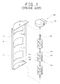
- Figures 1 through 3 are a side view, a partial enlarged sectional view, and an exploded perspective view of the main elements of a refrigerator having a device for dispersing cool air as disclosed in WO-A-95/27278.
- a refrigerator comprises freezing and fresh food compartments 2, 3 in a cabinet 1, which are separated from each other by a partition 5. Respective doors 6, 7 are provided for closing the compartments 2, 3.
- a cooling system comprising a compressor 11, a condenser (not shown), a freezing compartment evaporator 12a, and a fresh food compartment evaporator 12b, is installed in the cabinet 1. Cool air generated by the evaporators 12a, 12b is supplied to the corresponding compartments 2, 3 by a freezing compartment fan 13a and a fresh food compartment fan 13b respectively.
- a partially cylindrical duct plate 9 is attached to an inner wall plate 23 forming the rear inner wall surface of the fresh food compartment 3.
- the duct plate 9 has cool air discharge ports 16, opening into the fresh food compartment 3, formed in it.
- a supply duct 15 and a return duct 17, separated from each other by a seal plate 25, are provided between the duct plate 9 and the rear wall 4 of the cabinet 1.
- a duct member 21, for guiding downwards cool air blown by the fresh food compartment fan 13b, is installed in the supply duct 15. Cool air generated by the fresh food compartment evaporator 12b is blown by the fresh food compartment fan 13b and then supplied to the fresh food compartment 3 via the supply duct 15 and the cool air discharge ports 16.
- a cool air dispersing device 130 is installed in the supply duct 15.
- the cool air dispersing device 130 comprises a rotational shaft 131 having a vertical axis, cool air dispersing blades 132 assembled with the rotational shaft 131 in correspondence with respective cool air discharge ports 16, and a driving motor 135 for rotating the rotational shaft 131.
- Each of the cool air dispersing blades 132 comprises three discs 136, 137, 138 disposed in parallel with each other along the shaft 131, and first and second blade parts 133, 134 disposed between pairs of the discs 136, 137, 138.
- Each of the blade parts 133, 134 is curved so that its cross-section is loosely S-shaped.
- the blade parts 133, 134 are bent in opposite directions to each other.
- the blade parts 133, 134 of the cool air dispersing device 130 are S-shaped, the left or right sides of the fresh food compartment 3 may not be supplied with the cool air sufficiently and the smooth flow of cool air may be impeded by a vortices in the cool air formed about the cool air discharge ports 16.
- the present invention has been proposed to overcome the above-described problems in the prior art, and accordingly it is the object of the present invention to provide a refrigerator having a cool air dispersing device capable of preventing vortex of cool air and distributing the cool air effectively.
- a refrigerator according to the present invention is characterised by a pivotable blade for directing cool air being supplied to the compartment through the aperture, drive means for pivoting the blade, temperture sensing means for sensing the temperature distribution in the compartment and control means responsive to the output of the temperature sensing means to control the drive means such that the blade moves so as to direct cool air so as to tend to reduce temperature variations across the compartment.
- the blade maybe pivotable about a vertical axis or about horizontal axis.
- one blade is pivotable about a vertical axis and a further blade for directing cool air being supplied to the compartment through the aperture is pivotable about a horizontal axis.
- the further blade is preferably driven by said drive means.
- control means operates to continuously rotate the or each blade when the temperature variation across the compartment meets a predetermined criteria, for example a temperature differential.
- a refrigerator according to the present invention comprises a freezing compartment 2 and a cooling compartment 3 in a cabinet 1.
- the compartments 2, 3 are separated by a horizontal partition. Doors 6, 7 are provided respectively for the compartments 2, 3.
- Shelves 8 for supporting food are provided in the fresh food compartment 3 and divide it into three areas one above another.
- a special fresh chamber 18 for storing food that requires a specific temperature range is formed at the top of the fresh food compartment 3 and a vegetable chamber 19 for storing vegetables is formed at the bottom of the fresh food compartment 3.
- a heat pump comprising a compressor 11, a condenser (not shown), a freezing compartment evaporator 12a, and a fresh food compartment evaporator 12b, is installed in the cabinet 1.
- Cool air generated by the evaporators 12a, 12b is supplied into the corresponding cooling compartments 2, 3 by the freezing compartment fan 13a and the fresh food compartment fan 13b.
- a supply duct 15 and a return duct 17 are provided at the back of the fresh food compartment 3.
- the cool air generated by the fresh food compartment evaporator 12b is driven by the fresh food compartment fan 13b into the fresh food compartment 3 via the supply duct 15 and the cool air discharge ports 16.
- a device for dispersing the cool air horizontally is installed in the supply duct 15.
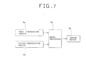
- a pair of temperature sensors 9a, 9b are installed in the fresh food compartment 3.
- the first temperature sensor 9a is installed in the upper left portion of the fresh food compartment 3 and the second temperature sensor 9b is installed in the lower right portion of the fresh food compartment 3.
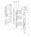
- the refrigerator has a device 30 for dispersing cool air horizontally and a device 40 for dispersing the cool air vertically.
- the horizontally-dispersing device 30 has a verical shaft 31, three horizontally-dispersing blades 33 having the shape of a planar plate, and a driving motor 35 for rotating the rotational shaft 31. Three horizontally-dispersing blades 33 are spaced along the shaft 31 near respective cool air discharge ports 16.
- a coupling part 39 at the upper end of the rotational shaft 31 is coupled to a drive shaft 36 of the driving motor 35 and a journal part 32 at the bottom of the rotational shaft 31 is rotatably received in a bearing hole 9g at the bottom of the duct plate 9.
- the driving motor 35 be a stepping motor whose angular stop position can be controlled.
- the horizontally-dispersing blades 33 are rotated by the rotational shaft 31, and cool air is discharged through the cool air discharge ports 16 and dispersed horizontally.
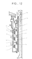
- the vertically-dispersing device 40 comprises a plurality of vertically-dispersing blades 57 which are disposed near the cool air discharge ports 16 and which are capable of pivoting about respective horizontal axes, a vertically reciprocable link member 61 in the supply duct 15, and a raising and lowering cam 63 for raising and lowering the link member 61.
- the vertically-dispersing blades 57 are arcute so as to accommodate the horizontally-dispersing blades 33, and a horizontal stub shaft 53 extend horizontally from the left and right ends thereof.
- the duct plate 9 has two opposed flange parts 9e which extend backward from its side margins.
- the flange parts 9e have a plurality of shaft holes 9f for receiving and rotatably supporting the stub shafts 53.
- the link member 61 is disposed parallel to the rotational shaft 31.
- the link member 61 is rod-shaped and has a plurality of partially ring-shaped hinge assembly parts 62 which protrude towards respective vertical- dispersing blades 57.
- Each of the vertically-dispersing blades 57 has a horizontal, cylindrical hinge part 55 at the middle of its front edge.
- the hinge assembly parts 62 are engaged by the hinge parts 73 so as to be capable of rotating relatively thereto.
- the raising and lowering cam 63 is installed on the rotational shaft 31.
- the raising and lowering cam 63 comprises a cylindrical cam body 66 and a cam groove 65 formed on the outer surface of the cam body 66.
- the cam groove 65 is a closed loop having a raising and lowering profile.
- On the link member 61 is provided an operation part 67 protruding transversely to the longitudinal direction of the link member and the free end of the operation part 67 is received in the cam groove 65.
- the link member 61 has a guiding piece 69 protruding toward the duct plate 9.
- the guiding piece 69 is accommodated in the raising and lowering guiding part 49 formed on the inner wall of the duct plate 9.
- the raising and lowering guiding part 49 accommodates the guiding piece 69 so as to guide it up and down and prevent the link member 61 from rotating.
- the cool air dispersing device is controlled by a microprocessor 70.
- the microprocessor 70 receives signals from the first and second temperature sensors 9a, 9b and calculates the temperture distribution on the basis of the sensed temperatures.
- the microprocessor 70 controls the driving motor 35 according to the calculated temperature distribution.
- the microprocessor 70 also controls the compressor 11 and the fans 13a, 13b to control the generation and supply of the cool air.
- the raising and lowering cam 63 rotates with the rotational shaft 31, and the link member 61 is raised and lowered by the operation part 67 which is engaged with the cam groove 65 of the raising and lowering cam 63.
- the up and down movement of the link member 61 causes pivoting of the vertically-dispersing blades 57 relatively to the horizontal rotational shaft 53 through the hinge assembly part 62 and the hinge part 55 of the vertically-dispersing blades 57.
- the raising and lowering of the link member 61 is guided vertically by the guiding piece 69 and the raising and lowering guiding part 49. Therefore, the link member 61 does not rotate but reciprocates in the vertical direction while the raising and lowering cam 63 rotates.
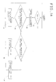
- the microprocessor 70 checks (step S1) whether the fresh food compartment fan 13b is running or not. If the fresh food compartment fan 13b is running, the microprocessor 70 senses the distribution of the temperature in the fresh food compartment 3 in order to perform the concentrative cooling according to the present invention.
- the microprocessor 70 senses (step S2) the temperature in the fresh food compartment 3 using the first and second temperature sensors 9a, 9b, and calculates (step S3) the difference between the temperatures at the sensed positions.
- the microprocessor 70 calculates the degree of the deviation of the temperatures on the basis of whether the temperature difference is over a predetermined value X or not.
- the predetermined value X is determined in consideration of the kind, size, and cooling capacity of the refrigerator, and is preferably determined to be from 2 to 3 degrees centigrade.
- step S4 the microprocessor 70 rotates (step S4) the rotational shaft 31 continuously in a constant speed. Therefore, the cool air is dispersed uniformly by the rotating horizontally-dispersing blades 33.
- the vertically-dispersing device 40 operates together while the horizontally-dispersing device 30 is operating, so cool air is dispersed uniformly in horizontal direction as well as vertical direction. Furthermore, since the horizontally-dispersing blades 33 are planar, vortices in the cool air flow are not generated by the horizontally-dispersing blades 33.
- the microprocessor 70 compares (step S5) the temperature of the first area sensed by the first temperature sensor 9a with the temperature of the second area sensed by the second temperature sensor 9b, and stops the driving motor 35 so that the horizontally-dispersing blades 33 are directed to the area of higher temperature.
- the concentrated cooling of a high temperature area is realized.
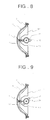
- step S6 controls the driving motor 35 so that the horizontally-dispersing blades 33 are rotated right as shown in Figure 10.
- the vertically-dispersing blades 57 are rotated upward as shown in Figure 13. Then the cool air is discharged to be concentrated on the first area.
- step S7 controls the driving motor 35 so that the horizontally-dispersing blades 33 are rotated left as shown in Figure 9.
- the vertically-dispersing blades 57 are rotated downward as shown in Figure 12.
- cool air is discharged so as to be concentrated on the second area. Since the cool air is discharged to the high temperature area in a concentrative manner, the temperature in the fresh food compartment 3 is maintained uniform.
- horizontally-dispersing blades 33 are disposed in correspondence with respective cool air discharge ports 16.
- a single long blade, extending past all of the cool air discharge ports 16, could be used.
- the vertically-dispersing blades 57 operate together with the horizontally-dispersing blades 33. However, they could be driven independently. That is, if an additional driving motor controlled by the microprocessor 70 is provided, and the link member 61 is operated not by the raising and lowering cam 63 but by the additional driving motor, it is possible to control independently the angular stop positions of the vertically-dispersing blades 57. Then, the concentrative cooling on a specific area or the dispersing of the cool air by continuous reciprocation can be performed in the vertical direction as well. In this case, it is preferable that a plurality of temperature sensors are provided at a plurality of respective positions.
- the highest temperature area can be detected from among a plurality of areas.
- the vertically-dispersing blades 57 and the horizontally-dispersing blades 33 which are controlled independently of each other, can then direct cool air to the detected high temperature area.
Landscapes
- Engineering & Computer Science (AREA)
- Chemical & Material Sciences (AREA)
- Combustion & Propulsion (AREA)
- Mechanical Engineering (AREA)
- General Engineering & Computer Science (AREA)
- Physics & Mathematics (AREA)
- Thermal Sciences (AREA)
- Cold Air Circulating Systems And Constructional Details In Refrigerators (AREA)
Applications Claiming Priority (2)
| Application Number | Priority Date | Filing Date | Title |
|---|---|---|---|
| KR9734633 | 1997-07-24 | ||
| KR1019970034633A KR100208357B1 (ko) | 1997-07-24 | 1997-07-24 | 냉기분배장치를 갖는 냉장고 및 냉장고의 제어방법 |
Publications (2)
| Publication Number | Publication Date |
|---|---|
| EP0893662A2 true EP0893662A2 (de) | 1999-01-27 |
| EP0893662A3 EP0893662A3 (de) | 1999-10-06 |
Family
ID=19515469
Family Applications (1)
| Application Number | Title | Priority Date | Filing Date |
|---|---|---|---|
| EP98305923A Withdrawn EP0893662A3 (de) | 1997-07-24 | 1998-07-24 | Kühlschrank mit Kühlluftleitvorrichtung |
Country Status (3)
| Country | Link |
|---|---|
| EP (1) | EP0893662A3 (de) |
| JP (1) | JPH11101552A (de) |
| KR (1) | KR100208357B1 (de) |
Cited By (1)
| Publication number | Priority date | Publication date | Assignee | Title |
|---|---|---|---|---|
| CN107642939A (zh) * | 2017-11-01 | 2018-01-30 | 南京创维家用电器有限公司 | 一种冰箱冷冻风道组件及冰箱 |
Families Citing this family (5)
| Publication number | Priority date | Publication date | Assignee | Title |
|---|---|---|---|---|
| KR100446779B1 (ko) * | 2002-07-26 | 2004-09-01 | 엘지전자 주식회사 | 냉장고의 2자유도 냉기공급장치 |
| KR100459457B1 (ko) * | 2002-08-14 | 2004-12-03 | 엘지전자 주식회사 | 냉장고의 냉장실내 고온부하 집중냉각방법 |
| KR100459459B1 (ko) * | 2002-08-20 | 2004-12-03 | 엘지전자 주식회사 | 냉장고의 냉장실 균일온도 제어장치 및 그 제어방법 |
| CN102192630B (zh) * | 2010-03-19 | 2013-09-04 | 海尔集团公司 | 一种用于电冰箱的出风调节装置及电冰箱 |
| CN106123386B (zh) * | 2016-06-17 | 2018-07-03 | 西安交通大学 | 一种大冷冻能力并联双循环制冷系统及其控制方式 |
Citations (1)
| Publication number | Priority date | Publication date | Assignee | Title |
|---|---|---|---|---|
| WO1995027278A1 (en) | 1994-03-30 | 1995-10-12 | Harrison & Sons Limited | Self-adhesive stamps |
Family Cites Families (5)
| Publication number | Priority date | Publication date | Assignee | Title |
|---|---|---|---|---|
| JPH04177074A (ja) * | 1990-11-13 | 1992-06-24 | Hitachi Ltd | 冷蔵庫 |
| GB2260831B (en) * | 1991-10-18 | 1995-02-15 | Toshiba Kk | Air conditioning apparatus having louver for changing the direction of air into room |
| KR200143520Y1 (ko) * | 1995-08-19 | 1999-06-15 | 윤종용 | 냉장고 |
| KR0162412B1 (ko) * | 1995-10-13 | 1999-02-18 | 구자홍 | 냉장고의 신규 부하 집중 냉각장치 |
| JP2993412B2 (ja) * | 1995-11-20 | 1999-12-20 | 三菱電機株式会社 | 吹出口及び該吹出口を備えた空気調和装置 |
-
1997
- 1997-07-24 KR KR1019970034633A patent/KR100208357B1/ko not_active Expired - Fee Related
-
1998
- 1998-07-23 JP JP10208380A patent/JPH11101552A/ja active Pending
- 1998-07-24 EP EP98305923A patent/EP0893662A3/de not_active Withdrawn
Patent Citations (1)
| Publication number | Priority date | Publication date | Assignee | Title |
|---|---|---|---|---|
| WO1995027278A1 (en) | 1994-03-30 | 1995-10-12 | Harrison & Sons Limited | Self-adhesive stamps |
Cited By (2)
| Publication number | Priority date | Publication date | Assignee | Title |
|---|---|---|---|---|
| CN107642939A (zh) * | 2017-11-01 | 2018-01-30 | 南京创维家用电器有限公司 | 一种冰箱冷冻风道组件及冰箱 |
| CN107642939B (zh) * | 2017-11-01 | 2020-07-10 | 南京创维家用电器有限公司 | 一种冰箱冷冻风道组件及冰箱 |
Also Published As
| Publication number | Publication date |
|---|---|
| EP0893662A3 (de) | 1999-10-06 |
| JPH11101552A (ja) | 1999-04-13 |
| KR19990011513A (ko) | 1999-02-18 |
| KR100208357B1 (ko) | 1999-07-15 |
Similar Documents
| Publication | Publication Date | Title |
|---|---|---|
| US12163722B2 (en) | Refrigerator | |
| US6131403A (en) | Refrigerator with a cool air dispersing device capable of preventing backflow of air in a cooling compartment | |
| EP0715136A1 (de) | Kühlschrank und Temperaturregelungsverfahren durch die Regelung der Austrittsrichtung der Kühlluft | |
| EP0895043A2 (de) | Kühlschrank | |
| EP0898134B1 (de) | Kühlschrank | |
| EP0893661B1 (de) | Kühlschrank mit Kühlluftverteilungsvorrichtung | |
| EP0893662A2 (de) | Kühlschrank mit Kühlluftleitvorrichtung | |
| EP0907059A2 (de) | Kühlschrank mit Kühlluftführungsvorrichtung | |
| EP0905462B1 (de) | Kühlverfahren eines Raumes | |
| EP0889293A2 (de) | Kühlschrank | |
| EP0895042B1 (de) | Kühlschrank | |
| EP0899524B1 (de) | Kühlschrank mit Kühlluftverteilungsmitteln | |
| EP0892227B1 (de) | Kühlschrank mit Kühlluftverteilungsvorrichtung | |
| EP0899526A2 (de) | Kühlschrank mit Kühlluftverteilungsmitteln | |
| EP0899525A2 (de) | Kühlschrank mit Kühlluftverteilvorrichtung | |
| EP0899523A2 (de) | Kühlschrank mit Kühlluftverteilvorrichtung | |
| EP0892228A2 (de) | Kühlschrank mit Kühlluftverteilungsvorrichtung | |
| EP0895041A2 (de) | Kühlschrank | |
| KR100222941B1 (ko) | 냉기분배장치를 갖는 냉장고 | |
| KR100229490B1 (ko) | 냉기분배장치를 갖는 냉장고 | |
| KR19990030702A (ko) | 냉기분배장치를 갖는 냉장고 |
Legal Events
| Date | Code | Title | Description |
|---|---|---|---|
| PUAI | Public reference made under article 153(3) epc to a published international application that has entered the european phase |
Free format text: ORIGINAL CODE: 0009012 |
|
| AK | Designated contracting states |
Kind code of ref document: A2 Designated state(s): AT BE CH CY DE DK ES FI FR GB GR IE IT LI LU MC NL PT SE |
|
| AX | Request for extension of the european patent |
Free format text: AL;LT;LV;MK;RO;SI |
|
| PUAL | Search report despatched |
Free format text: ORIGINAL CODE: 0009013 |
|
| AK | Designated contracting states |
Kind code of ref document: A3 Designated state(s): AT BE CH CY DE DK ES FI FR GB GR IE IT LI LU MC NL PT SE |
|
| AX | Request for extension of the european patent |
Free format text: AL;LT;LV;MK;RO;SI |
|
| AKX | Designation fees paid | ||
| REG | Reference to a national code |
Ref country code: DE Ref legal event code: 8566 |
|
| STAA | Information on the status of an ep patent application or granted ep patent |
Free format text: STATUS: THE APPLICATION IS DEEMED TO BE WITHDRAWN |
|
| 18D | Application deemed to be withdrawn |
Effective date: 20000407 |