EP0893677A1 - Appareils et méthodes pour mesurer la pression par perte de chaleur - Google Patents
Appareils et méthodes pour mesurer la pression par perte de chaleur Download PDFInfo
- Publication number
- EP0893677A1 EP0893677A1 EP98102089A EP98102089A EP0893677A1 EP 0893677 A1 EP0893677 A1 EP 0893677A1 EP 98102089 A EP98102089 A EP 98102089A EP 98102089 A EP98102089 A EP 98102089A EP 0893677 A1 EP0893677 A1 EP 0893677A1
- Authority
- EP
- European Patent Office
- Prior art keywords
- sensing element
- resistance
- gauge
- temperature
- pressure
- Prior art date
- Legal status (The legal status is an assumption and is not a legal conclusion. Google has not performed a legal analysis and makes no representation as to the accuracy of the status listed.)
- Granted
Links
Images



Classifications
-
- G—PHYSICS
- G01—MEASURING; TESTING
- G01L—MEASURING FORCE, STRESS, TORQUE, WORK, MECHANICAL POWER, MECHANICAL EFFICIENCY, OR FLUID PRESSURE
- G01L21/00—Vacuum gauges
- G01L21/10—Vacuum gauges by measuring variations in the heat conductivity of the medium, the pressure of which is to be measured
- G01L21/12—Vacuum gauges by measuring variations in the heat conductivity of the medium, the pressure of which is to be measured measuring changes in electric resistance of measuring members, e.g. of filaments; Vacuum gauges of the Pirani type
Definitions
- the present invention relates to a heat loss gauge utilizing gas conduction for measuring pressures, ranging from very low pressures to pressures greater than atmospheric pressure.
- the pressure sensor in a Pirani gauge the pressure sensor consists of a temperature sensitive resistance RS connected as one arm of a Wheatstone bridge.
- R2 is typically a temperature sensitive resistance designed to have a negligible temperature rise due to the current i 2 .
- R3 and R4 are typically fixed resistances.
- RS and typically R2 are exposed to the vacuum environment whose pressure is to be measured.
- Figure 1b illustrates an alternative bridge configuration.
- Pirani gauges have been operated with constant current i 1 (as shown in U.S. Patent 3,580,081), or with constant voltage across RS. In these methods, an electrical imbalance of the bridge is created which reflects gas pressure. Pirani gauges have also been operated with constant resistance RS (as shown In U.S. Patent 2,938,387). In this mode, the rate at which energy is supplied is varied with changes in gas pressure, so the rate of change in energy supplied reflects changes In gas pressure. Each method of operation has differing advantages and disadvantages, but the following discussion pertains particularly to the constant resistance method and the configuration of Figure 1a.
- Voltage V B is automatically controlled to maintain the voltage difference between A and C in Fig. 1a at zero volts.
- the bridge is said to be balanced.
- a conventional Pirani gauge is calibrated against several known pressures to determine a relationship between unknown pressure, P X , and the power loss to the gas or more conveniently to the bridge voltage. Then, assuming end losses and radiation losses remain constant, the unknown pressure of the gas P X may be directly determined by the power lost to the gas or related to the bridge voltage at bridge balance.
- Pirani gauges may be designed to have wide range and are relatively simple and inexpensive, there is a long-felt need to be able to use these gauges as a substitute for much higher priced gauges such as capacitance manometers and ionization gauges.
- existing designs leave much to be desired for accurate pressure measurement, especially at lower pressures.
- the CONVECTRON® Gauge filled an unsatisfied need, it has several disadvantages. It has by necessity large internal dimensions to provide space for convection. Therefore, it is relatively large. Because convection is gravity dependent, pressure measurements at higher pressures depend on the orientation of the sensor axis. Also, because the pressure range where gas conduction cooling is predominant does not neatly overlap the pressure range where convection cooling occurs, the CONVECTRON® Gauge has limited sensitivity from approximately 20 to 200 Torr.
- Pirani sensors have been developed which utilize sensor-to-wall spacings on the order of a few microns rather than the much larger spacings, e.g., 0.5 in., previously used. See for example U.S. Patents 4,682,503 to Higashi et al. and 5,347,869 to Shie et al. W. J. Alvesteffer et al., in an article appearing in J. Vac. Sci. Technol. A 13(6), Nov/Dec 1995, describe the most recent work on Pirani gauges known to the present inventors. Using such small sensor to wall spacings provides a pressure dependent thermal conductivity even at pressures above atmospheric pressure. Thus, such microscopic sensors have good sensitivity from low pressure to above atmospheric pressure and function in any orientation.
- microminiature sensors provide good sensitivity over a large pressure range independent of orientation, their design is extremely complex and fabrication requires numerous elaborate processing steps in highly specialized equipment costing hundreds of thousands of dollars.
- Microminiature sensors suffer from the same type of ambient temperature-caused errors as do macroscopic sensors. All of the heat loss terms in Eq. 7 are dependent on ambient temperature and on sensing element temperature at any given pressure. Thus, any attempt at pressure measurement with a Pirani gauge without temperature correction will be confused by non-pressure dependent power losses caused by changes in ambient temperature. All modern Pirani gauges attempt to correct for the errors caused by ambient temperature changes. A widely used means for correcting for such errors is to use for R2 a temperature sensitive compensating element RC In series with a fixed resistance R, as shown in Figs. 1a and 1b.
- British Patent GB 2105047A discloses the provision of an additional resistor to provide a potential divider.
- J.H. Leck at page 58 of Pressure Measurement in Vacuum , Chapman and Hall: London (1964) notes that Hale in 1911 made R2 of the same material and physical dimensions as PS in his Pirani gauge. R2 was sealed off in its own vacuum environment and placed in close proximity to RS. When the pressures at R2 and RS were equal, excellent temperature compensation was achieved. However, at other pressures this means of temperature compensation is not very effective.
- R2 is conventionally placed in the same vacuum environment as RS.
- Leck recommends that R2 be "made in two sections, for example, one of copper and the other Nichrome wire . . . so that the overall temperature coefficient (of R2) just matches that of the Pirani element itself (RS)."
- this method of temperature compensation has been used by Edwards High Vacuum of Great Britain In the METROVAC® brand gauge. A similar temperature compensation arrangement is used in the CONVECTRON® brand gauge.
- the inventors have also found, through extensive computer simulation, that using equal temperature coefficients for RS and R2 as recommended by Leck and as practiced In the prior art does not provide an entirely accurate temperature compensation.
- the inventors have also found that at pressures less than approximately 5 x 10 -3 Torr, the end losses exceed all other losses combined.
- the relative loss components as determined by this research (radiation loss, end loss and gas loss components of total loss) are shown in the graph of Fig. 2. At 1 x 10 -5 Torr, the end losses are over 1000 times greater than the gas loss and radiation losses are approximately 100 times greater than the gas loss.
- Prior art heat loss gauges cannot measure very low pressures accurately, for example, 1 x 10 -5 Torr.
- the inventors have discovered that this limitation is a result of failure to maintain end losses in the sensing element sufficiently constant when ambient temperature changes.
- the Alvesteffer-type Pirani gauge has the capability of indicating pressure in the 10 -5 Torr range, but does not provide an accurate indication within that range. For example, if the end losses are not held constant to one part in 5,000 in a typical Pirani gauge, a pressure indication at 1 x 10 -5 Torr may be off by 50% to 100%.
- Fig. 3 is a schematic representation of a portion 302 of a conventional Pirani gauge using a small diameter wire sensing element 304 and a compensating element 303.
- small diameter wire sensing element 304 is electrically and thermally joined to much larger electrical connectors 306, 307 which are thermally joined to much larger support structures 308, 309.
- T AL represent the temperature in support structure 308 at the left end of sensing element 304
- T AR represent the temperature in support structure 309 at the right end at any given time t.
- T SL and T SR represent the temperatures at left sensing element connector 306 and right sensing element connector 307 respectively.
- T CL and T CR represent the temperatures at left compensating element connector 310 and right compensating element connector 311 respectively.
- T XL and T XR represent the temperatures a distance ⁇ X from connectors 306 and 307 respectively. In prior art designs, it has apparently been assumed that all of these temperatures are the same. However, the inventors have found that even seemingly negligible differences assume great importance for low pressure accuracy.
- T AR T AL +T CR 2 will increase.
- T XL and T XR T XR at bridge balance, which will produce changes in ⁇ L and ⁇ R .
- ⁇ L and ⁇ R will change the end loss term in Eq. 7, causing an error in pressure measurement dependent on the size of the changes in ⁇ L and ⁇ R .
- sensing element and compensating element connectors have substantially identical physical dimensions and substantially identical thermal properties, sensing element end losses will not remain unchanged when ambient temperature changes.
- Prior art Pirani gauges have not been specifically designed so that sensing and compensating element connectors have identical physical dimensions and thermal properties.
- T AVG will continually change, thus continually changing T XL and T XR at bridge balance.
- ⁇ L and ⁇ R will change during the lag time, sensing element end losses will not remain constant, and errors will be produced in low pressure measurement.
- Prior art Pirani gauges when configured as in Fig. 1a, have the same pressure dependent current in RS as is in the compensating element at bridge balance. When configured as in Fig. 1b, at balance the same pressure dependent voltage is applied across R2 as across RS. Of course, a pressure dependent current in R2 will cause the temperature of RC to rise above ambient temperature by an amount which varies with pressure.
- Prior art Pirani gauges typically use a compensating element of much larger physical dimensions than the sensing element, to dissipate the heat and thus prevent excessive temperature in the compensating element. As noted above, different physical dimensions for the sensing and compensating elements cause measurement errors when ambient temperature changes.
- a fourth problem is that prior art Pirani gauges produce shifts in pressure indications at low pressures when ambient temperature changes.
- Prior art Pirani gauges have used a variety of components in attempting to maintain the power lost by the sensing element unchanged as ambient temperature changes. For example, in U.S. Pat. 4,682,503 thermoelectric cooling is used to control ambient temperature and thus minimize ambient temperature changes.
- a thermally sensitive element is mounted adjacent to the compensating arm of the bridge (actually glued to the exterior of the vacuum enclosure in a commercial version).
- Alvesteffer et al. use an additional element (designated therein as R4) in the bridge to help compensate for the fact that the temperature coefficient of resistance is slightly different for the sensing element at operating temperature, compared to the compensating element at ambient temperature.
- Another general objective of the invention is to provide an improved Pirani-type pressure gauge with a circuit that applies a heating current to a temperature sensing element, without applying the heating current to an associated compensating element.
- Another, more specific objective of the invention is to provide an improved Pirani-type pressure gauge wherein a compensating element has physical dimensions substantially equal to those of a sensing element and is located in spaced relationship to the sensing element, in the same plane as the sensing element, and is made of the same material as the sensing element.
- a further objective of the invention is to provide an improved heat loss pressure gauge with thermally conductive elements placed near a sensing element to equalize temperatures across the sensing element.
- Another objective of the invention is to provide an improved heat loss pressure gauge including a means for maintaining a desired spacing between the sensing element and thermally conductive elements to compensate for expansion and contraction of the sensing element in response to changes in ambient temperature.
- Another objective of the invention is to provide an improved pressure gauge wherein physical dimensions and thermal conductivity of heat flow paths of a sensing element are substantially equal to physical dimensions and thermal conductivity of heat flow paths of a compensating element.
- a further objective of the invention is to provide an improved heat loss pressure gauge in which a heating means produces a fixed differential between resistance of a sensing element and resistance of a compensating element at ambient temperature, without applying heating voltage or current to the compensating element.
- Another objective is to provide an improved heat loss pressure gauge that uses a DC heating voltage.
- An additional general objective of the invention is to provide improved methods of temperature compensation for use in a Pirani-type gauge.
- a more specific objective of the invention is to provide an improved method of temperature compensation for use in a Pirani gauge in which sensing device voltage and current values are recorded for a series of pressures and ambient temperatures to define a calibration surface having three or more dimensions.
- Another objective of the invention is to provide an improved method of temperature compensation for use in a Pirani gauge wherein accurate calibration can be obtained using a model with only three dimensions, e.g. pressure, voltage, and current.
- An additional objective of the Invention is to provide a heat loss pressure gauge using a bridge circuit with two fixed elements, a sensing element, and a compensating element, wherein resistance of one fixed bridge element multiplied by resistance of the compensating element at a given temperature multiplied by a temperature coefficient of the compensating element for that temperature is substantially equal to the resistance of the other fixed bridge element multiplied by resistance of the sensing element multiplied by the temperature coefficient of the sensing element for the given temperature.
- a small diameter wire sensing element is positioned in the same plane as and spaced from a small diameter wire compensating element with two parallel flat thermally conductive plates, each spaced 15 microns from the sensing and compensating elements.
- the inventors have achieved high relative sensitivity in simple geometry without relying on convection.
- the extreme complexity and cost of microminiature Pirani gauge designs and the several disadvantages of convection cooling of the sensing element are simultaneously avoided.
- this improvement also provides a sensing element with a volume of only 3% that of the sensing element in the microminiature Alvesteffer gauge.
- the compensating element in the new device has a volume of less than 0.5% of the Alvesteffer-type compensating element.
- the present invention also provides improved temperature correction.
- the inventors have found that the accuracy of low pressure measurement can be significantly improved by better maintaining constant the temperature gradient ⁇ at the ends of the sensing element (see Eqs. 10 and 11).
- the inventors have found that constancy of ⁇ can be achieved by simultaneously:
- the compensating element can be made with identical dimensions of the sensing element as well as identical physical properties.
- a DC heating current is used and confined to only the sensing element.
- a relatively small AC signal is used to sense bridge balance.
- an additional performance improvement is realized by providing a new method of pressure compensation that results in accurate pressure indication at all pressures.
- an accurate indication of an unknown pressure P X at bridge balance may be calculated from a simple equation of the form of Eq. 26.
- VS is the voltage drop across the sensing element
- IS is the current in the sensing element.
- the particulars of Eq. 26 are derived from paired values of VS C and IS C obtained by calibration methods for multiple known values of pressure P C and ambient temperature spread across the pressure and temperature ranges of interest, using three-dimensional curve fitting software.
- VS X and IS X are measured at the unknown pressure P X at bridge balance and substituted into Eq. 26. Then, P X is calculated using a microprocessor or the like.
- the present invention provides significant advancements in Pirani gauge accuracy, production cost, and package size.
- the invention will be described in terms of four categories of improvements to conventional Pirani gauge designs.
- the four improvements are used together, and combine synergistically to provide a Pirani gauge having substantially improved performance characteristics.
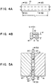
- Figure 4a is a side view of a portion 10 of an improved heat loss gauge (not to scale).
- Figure 4b is a sectional view of portion 10 taken along line 4b-4b in Figure 4a.
- a small diameter wire sensing element 12 is located in the same plane and spaced a distance d from a small diameter wire compensating element 14. Spacing d between sensing element 12 and compensating element 14 is preferably approximately 0.030 in. but may range from 0.010 in. to 0.200 in.
- Parallel plates 16 and 16' are provided proximate to and parallel to sensing element 12 and compensating element 14.
- Parallel plates 16 and 16' are positioned a distance S from sensing element 12 and compensating element 14.
- S is preferably 0.0007 in. but may range from 0.0002 in. to 0.002 in.
- Sensing element 12 is made of a material with a high temperature coefficient of resistance, such as pure tungsten, which may be gold plated to help assure a constant emissivity.
- the diameter of sensing element 12 is preferably 0.0005 in. but may range from 0.0001 in. to 0.002 in. Although a cylindrical wire shape is preferred, other shapes such as a ribbon may be used for both the sensing and compensating elements.
- the length of sensing element 12 is preferably 1 in. but may range from 0.25 in. to 3 in.
- Compensating element 14 is made of the same material as the sensing element 12 with the same physical dimensions, and with the same thermal and resistance properties.
- Portion 10 of the heat loss gauge may be installed in a measuring circuit of the type shown in Fig. 6, in a manner which will be described in more detail below.
- Parallel plates 16 and 16' conduct heat and thereby tend to equalize-temperature gradients along heated sensing element 12 and between the ends of sensing element 12 and compensating element 14.
- the invention achieves high relative sensitivity with a simple structure, and without relying on convection.
- the accuracy of low pressure measurement is significantly improved by using sensing and compensating elements with substantially identical physical dimensions, thermal properties and resistance properties, and locating the sensing and compensating elements in the same vacuum environment.
- the extreme complexity and cost of microminiature Pirani gauge designs and disadvantages associated with convection cooling of the sensing element are simultaneously avoided. This improvement permits pressure measurement results up to atmospheric pressure comparable to those obtained with very complex microminiature Pirani gauges, and comparable to those obtained with much larger, position sensitive convection cooled Pirani gauges.
- an improved mounting arrangement is provided for the sensing and compensating elements.
- the accuracy of low pressure measurement is significantly improved by using sensing element and compensating element connections with substantially identical physical dimensions, thermal properties and resistance properties, and by using element connections with substantially identical and large thermal conductances to a region of substantially uniform temperature for all connections.
- Fig. 5a is a greatly enlarged cross-sectional view of one end of gauge portion 10 where the sensing element 12 is supported by and electrically connected to sensing element connectors 20 and 20' and the compensating element 14 is shown supported by and electrically connected to compensating element connectors 22 and 22'.
- the section of Fig. 5a is taken along line 5a-5a in Figure 4a.
- identical supports are provided at each end of gauge portion 10.
- Connectors 20, 20', 22 and 22' are preferably made of platinum ribbon, 0.001 in. thick by 0.060 in. wide.
- Plates 16 and 16' are preferably made of an electrically insulating material with a high thermal conductivity such as aluminum nitride.
- sensing and compensating element connectors 20, 20', 22 and 22' can be electrically insulated from the plates 16 by thin electrically insulating layers 24 and 24' which may be a diamond-like coating on tungsten.
- Plates 16 and 16' may be made of a high thermal conductivity material such as tungsten.
- the selected material has a thermal conductivity greater than 0.25 watts/cm/K.
- Plates 16 and 16' are held in position by simple sheet metal clamps at each end (not shown). The clamps apply sufficient force to the plates 16 and 16' to embed the sensing element 12 and the compensating element 14 into the connectors 20, 20', 22 and 22' until the connectors 20 and 20', and 22 and 22' are in intimate contact.
- the spacing S between the sensing element 12 and the surface of the plates 16 and 16' is determined by the diameter of the sensing element and the thickness of the thin ribbon connectors 20, 20', 22, and 22'.
- Plates 16 and 16' provide a region of substantially uniform temperature, especially when isolated in vacuum with minimal thermal conductivity to the outside world.
- the thin ribbon connectors 20, 20', 22 and 22' provide identical dimensions, short path and very large thermal conductances to said region of uniform temperature, thus satisfying several of the conditions for constancy of temperature gradient, ⁇ , at the ends of the sensing element.
- Sensing element 12 may be suitably tensioned as shown in Fig. 5b by a small diameter wire spring 26 which is loaded during assembly and bears on sensing element 12 adjacent to said connector 21 of sensing element 12.
- Spring 28 is used in a similar manner to tension the compensating element 14.
- Springs 26 and 28 serve to maintain precise spacing of the sensing element 12 and compensating element 14 relative to plates 16 and 16' as ambient temperature changes.
- Sufficient slack must be built into the sensing element 12 and compensating element 14 assemblies to prevent breakage due to differential thermal expansion of the elements 12 and 14 and the plates 16. Without the springs 26 and 28, this slack would change with ambient temperature, thus preventing maintenance of constant spacing S between the parallel plates 16 and 16' and the sensing and compensating elements, respectively, and causing measurement errors.
- Eq. 22 is partially satisfied by the fact that sensing element 12 and compensating element 14 are physically, electrically, and thermally identical.
- Eq. 22 is fully satisfied at all times by this design.
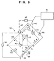
- a third major feature of the invention is an apparatus and method for independently heating sensing element 12. This improvement is illustrated in Fig. 6 wherein a Wheatstone bridge 30 is modified to provide independent heating of sensing element 12.
- Prior art circuits used with a compensating element with the same physical dimensions and made of the same material as the sensing element as in the present invention, cause the compensating element to operate not at ambient temperature but at the same temperature as the sensing element.
- Pirani gauges with the inventive improvements described above cannot achieve their accuracy potential using prior art heating circuits.
- a Wheatstone bridge 30 with nodes A, B, C, and D is provided with sensing element 12 having resistance value RS, connected between nodes B and C.
- Non-temperature sensitive resistance element 15 having resistance R
- compensating element 14 having resistance RC
- R2 and capacitor 36 are connected In series order between nodes C and D.
- Resistor 17 having value R4 is connected between nodes A and B, and resistor 19 having value R3 is connected between nodes A and D.
- Vacuum environment 34 encloses sensing element 12 and compensating element 14.
- AC voltage source 38 is connected between nodes B and D, and frequency selective detector 40 is connected between nodes A and C.
- DC current source 32 is connected between nodes B and C to provide current to node B.
- Controller 42 is connected, via automatic feedback linkages 46 and 47, so as to control DC current source 32 and so as to receive a voltage detection input from frequency selective detector 40 for purposes of that control.
- Vacuum environment 34 encloses a portion 10 (as shown in Figures 4a and 4b and described above with reference to those Figures) comprising sensing element 12, compensating element 14, and plates 16 and 16'.
- the assembly method described previously with reference to Figs. 5a and 5b is preferably used in the circuit of Fig. 6.
- Element connectors 20 and 20' at one end of sensing element 12 are electrically connected to Point C in bridge circuit 30 of Fig. 6, while sensing element connectors 21 and 21' (not shown) at the other end of sensing element 12 are electrically connected to Point B in Fig. 6.
- Compensating element connectors 22 and 22' at one end of compensating element 14 are electrically connected through capacitor 36 to Point D in Fig. 6, while the other end of compensating element 14 is connected to compensating element connectors 23 and 23' which are connected through a resistance 15 to Point C.
- DC current source 32 furnishes heating current I to sensing element 12 which is located in the vacuum environment 34.
- a capacitor 36 is provided as a means for preventing current from current source 32 from being present in R2, R3 and R4.
- no portion of the heating current or heating voltage in RS is present in R2 at any time.
- AC voltage source 38 applies an AC signal voltage to bridge 30 producing AC signal currents i S , i 2 , i 3 , and i 4 .
- bridge balance can be detected with negligible heating produced in any arm of bridge 30.
- the DC current I from source 32 is automatically adjusted by controller 42, so as to continually assure that the AC voltage drop i S RS from point B to C is equal to the voltage drop i 4 R4 from B to A as measured by the AC voltage detecting function of frequency selective detector 40.
- This automatic feedback linkage is indicated by dashed lines 46 and 47.
- Processor 51 is connected to current meter 49 and to voltage meter 48, and produces an output indicative of pressure in the vacuum environment 34 based on the level of heating current and through sensing element 12 and the voltage drop across sensing element 12.
- compensating element 14 may be made with the same physical dimensions and thermal and resistance properties as sensing element 12 and still operate at ambient temperature without any pressure dependent electrical heating.
- sensing element 12 is exposed to a series of known representative pressures and ambient temperatures spread over the pressure and temperature ranges of interest.
- the voltage drop, VS C as measured by voltmeter 48 and the current, IS C , as measured by current meter 49 are recorded together at bridge balance with each of the known representative calibration pressures, P C .
- These values may be recorded by a program operating in processor 51 or may be transferred to another processing unit for calibration calculations.
- the pressure P C is plotted against voltage VS C and current IS C .
- Each series of measurements at a given calibration temperature produces a constant temperature function relating pressure to voltage and current.
- the resulting calibration data may be stored in a lookup table and measured pressures can be determined by interpolating between pressure values stored in the lookup table based on the measured voltage drop and current.
- an approximating equation is obtained for the surface on which the measured values lie. This can readily be accomplished using three-dimensional surface plotting software.
- the resulting equation is of the form shown in Eq. 26.
- Eq. 27 can be stored In processor 51 which can then be used to automatically calculate P X when VS X and IS X are Input to processor 51.
- W and R can be calculated from the output of voltmeter 48 and current meter 49.
- the two selected parameters include information relating to both current and voltage, such that the effects of changes in current and voltage will be differentially reflected in the calibration graph or table created based on values of the two parameters.
- the two input parameters for the function may be any two of a group including: power, current, voltage, and resistance.
- This improvement provides excellent temperature compensation from 0°C to 50°C from pressures less than 10 -4 Torr to above atmospheric pressure. It avoids the need to measure power and temperature as is sometimes done. It compensates for all types of ambient temperature change induced errors, such as change in radiation loss, not merely those losses dependent on changes In sensing element to wall temperature changes as is the case in U.S. Pat. 4,682,503.
- the improvement avoids the complexity of having to control the ambient temperature using thermoelectric cooling as described in U.S. Pat. 5,347,869.
- this improved calibration and operating method automatically compensates for the fact that the temperature coefficient of resistivity will be slightly different for the sensing element at operating temperature than for the compensating element at ambient temperature.
Landscapes
- Physics & Mathematics (AREA)
- General Physics & Mathematics (AREA)
- Measuring Fluid Pressure (AREA)
Applications Claiming Priority (2)
| Application Number | Priority Date | Filing Date | Title |
|---|---|---|---|
| US08/897,629 US6023979A (en) | 1997-07-21 | 1997-07-21 | Apparatus and methods for heat loss pressure measurement |
| US897629 | 1997-07-21 |
Publications (2)
| Publication Number | Publication Date |
|---|---|
| EP0893677A1 true EP0893677A1 (fr) | 1999-01-27 |
| EP0893677B1 EP0893677B1 (fr) | 2002-01-16 |
Family
ID=25408155
Family Applications (1)
| Application Number | Title | Priority Date | Filing Date |
|---|---|---|---|
| EP98102089A Expired - Lifetime EP0893677B1 (fr) | 1997-07-21 | 1998-02-06 | Pirani dans lequel seule la résistance de mesure est chauffante |
Country Status (4)
| Country | Link |
|---|---|
| US (2) | US6023979A (fr) |
| EP (1) | EP0893677B1 (fr) |
| JP (1) | JP2839244B1 (fr) |
| DE (1) | DE69803147T2 (fr) |
Cited By (2)
| Publication number | Priority date | Publication date | Assignee | Title |
|---|---|---|---|---|
| FR2809812A1 (fr) * | 2000-05-31 | 2001-12-07 | Helix Tech Corp | Appareil et procedes de mesure de pression par perte de chaleur |
| US20040216527A1 (en) * | 1997-07-21 | 2004-11-04 | Helix Technology Corporation | Apparatus and methods for heat loss pressure measurement |
Families Citing this family (35)
| Publication number | Priority date | Publication date | Assignee | Title |
|---|---|---|---|---|
| JP3555844B2 (ja) * | 1999-04-09 | 2004-08-18 | 三宅 正二郎 | 摺動部材およびその製造方法 |
| US20110301569A1 (en) | 2001-01-20 | 2011-12-08 | Gordon Wayne Dyer | Methods and apparatus for the CVCS |
| KR100407815B1 (ko) * | 2001-05-04 | 2003-12-01 | 학교법인 포항공과대학교 | 펠티어 효과를 이용한 열전도형 진공 게이지 |
| JP2004138128A (ja) | 2002-10-16 | 2004-05-13 | Nissan Motor Co Ltd | 自動車エンジン用摺動部材 |
| US6969198B2 (en) * | 2002-11-06 | 2005-11-29 | Nissan Motor Co., Ltd. | Low-friction sliding mechanism |
| JP3891433B2 (ja) * | 2003-04-15 | 2007-03-14 | 日産自動車株式会社 | 燃料噴射弁 |
| EP1479946B1 (fr) * | 2003-05-23 | 2012-12-19 | Nissan Motor Co., Ltd. | Piston pour un moteur à combustion interne |
| EP1482190B1 (fr) * | 2003-05-27 | 2012-12-05 | Nissan Motor Company Limited | Elément de roulement |
| JP2005008851A (ja) * | 2003-05-29 | 2005-01-13 | Nissan Motor Co Ltd | 硬質炭素薄膜付き機械加工工具用切削油及び硬質炭素薄膜付き機械加工工具 |
| JP2004360649A (ja) | 2003-06-06 | 2004-12-24 | Nissan Motor Co Ltd | エンジン用ピストンピン |
| JP4863152B2 (ja) * | 2003-07-31 | 2012-01-25 | 日産自動車株式会社 | 歯車 |
| EP1666573B1 (fr) * | 2003-08-06 | 2019-05-15 | Nissan Motor Company Limited | Mecanisme coulissant a faible frottement et procede de reduction de frottement |
| JP4973971B2 (ja) * | 2003-08-08 | 2012-07-11 | 日産自動車株式会社 | 摺動部材 |
| JP2005054617A (ja) * | 2003-08-08 | 2005-03-03 | Nissan Motor Co Ltd | 動弁機構 |
| JP4117553B2 (ja) * | 2003-08-13 | 2008-07-16 | 日産自動車株式会社 | チェーン駆動装置 |
| DE602004008547T2 (de) | 2003-08-13 | 2008-05-21 | Nissan Motor Co., Ltd., Yokohama | Struktur zur Verbindung von einem Kolben mit einer Kurbelwelle |
| JP4539205B2 (ja) | 2003-08-21 | 2010-09-08 | 日産自動車株式会社 | 冷媒圧縮機 |
| US7771821B2 (en) * | 2003-08-21 | 2010-08-10 | Nissan Motor Co., Ltd. | Low-friction sliding member and low-friction sliding mechanism using same |
| EP1508611B1 (fr) | 2003-08-22 | 2019-04-17 | Nissan Motor Co., Ltd. | Boîte de vitesse comprenant une composition d`huile de transmission |
| US7249516B2 (en) * | 2004-07-28 | 2007-07-31 | Brooks Automation, Inc. | Method of operating a resistive heat-loss pressure sensor |
| WO2006020196A1 (fr) | 2004-07-28 | 2006-02-23 | Brooks Automation, Inc. | Procedez de fonctionnement d'un capteur de pression a perte d'energie et a resistance |
| US20060021444A1 (en) * | 2004-07-28 | 2006-02-02 | Helix Technology Corporation | Method of operating a resistive heat-loss pressure sensor |
| US7418869B2 (en) | 2005-06-10 | 2008-09-02 | Brooks Automation, Inc. | Wide-range combination vacuum gauge |
| US7207224B2 (en) * | 2005-06-10 | 2007-04-24 | Brooks Automation, Inc. | Wide-range combination vacuum gauge |
| US7331237B2 (en) * | 2006-02-01 | 2008-02-19 | Brooks Automation, Inc. | Technique for improving Pirani gauge temperature compensation over its full pressure range |
| US7278322B1 (en) | 2006-03-30 | 2007-10-09 | International Business Machines Corporation | Semiconductor based pressure sensor |
| DE102007053943C5 (de) | 2007-11-09 | 2017-11-23 | Vacuubrand Gmbh + Co Kg | Wärmeleitungs-Gasdruckmeßanordnung |
| DE102007053944A1 (de) | 2007-11-09 | 2009-05-20 | Vacuubrand Gmbh + Co Kg | Wärmeleitungs-Gasdruckmeßanordnung |
| DE102013012434A1 (de) | 2012-07-30 | 2014-01-30 | Heinz Plöchinger | Sensoren zur Erfassung von Fluid-Eigenschaften mit Wärmeverlustausgleich und dessen Betriebsweise |
| DE102014013270A1 (de) | 2014-09-12 | 2016-03-17 | Vaccubrand Gmbh + Co Kg | Gasdruckmessvorrichtung |
| DE202014007298U1 (de) | 2014-09-12 | 2015-12-16 | Vacuubrand Gmbh + Co Kg | Gasdruckmessvorichtung |
| US10436665B2 (en) | 2017-06-01 | 2019-10-08 | Heinz Plöchinger | Fluid property sensor with heat loss compensation and operating method thereof |
| US10845263B2 (en) * | 2018-04-17 | 2020-11-24 | Mks Instruments, Inc. | Thermal conductivity gauge |
| GB2602040A (en) * | 2020-12-16 | 2022-06-22 | Edwards Ltd | Thermal conductivity vacuum gauge assembly |
| US12123794B2 (en) | 2022-10-11 | 2024-10-22 | Mks Instruments, Inc. | Pirani gauge with model of power dissipation |
Citations (5)
| Publication number | Priority date | Publication date | Assignee | Title |
|---|---|---|---|---|
| DE1094341B (de) * | 1958-12-13 | 1960-12-08 | Cons Electrodynamics Corp | Anordnung zur selbsttaetigen Steuerung der Temperatur eines stromdurchflossenen Widerstandes |
| DE1648592A1 (de) * | 1967-10-25 | 1971-04-01 | Leybold Heraeus Gmbh & Co Kg | Messverfahren zur Messung kleiner Differenzdruecke |
| US5347869A (en) * | 1993-03-25 | 1994-09-20 | Opto Tech Corporation | Structure of micro-pirani sensor |
| US5557972A (en) * | 1994-09-13 | 1996-09-24 | Teledyne Industries, Inc. | Miniature silicon based thermal vacuum sensor and method of measuring vacuum pressures |
| US5597957A (en) * | 1993-12-23 | 1997-01-28 | Heimann Optoelectronics Gmbh | Microvacuum sensor having an expanded sensitivity range |
Family Cites Families (18)
| Publication number | Priority date | Publication date | Assignee | Title |
|---|---|---|---|---|
| US1448540A (en) * | 1917-07-14 | 1923-03-13 | Western Electric Co | Apparatus for measuring gas pressures |
| US1668106A (en) * | 1923-07-26 | 1928-05-01 | Bbc Brown Boveri & Cie | Hot-wire vacuum meter |
| US1778508A (en) * | 1925-10-20 | 1930-10-14 | Western Electric Co | Apparatus for measuring and recording pressures |
| US1873984A (en) * | 1928-09-14 | 1932-08-30 | Sieber Fritz | Indicating device |
| US2938387A (en) * | 1956-12-10 | 1960-05-31 | Cons Vacuum Corp | Automatic control circuit |
| US3199356A (en) * | 1961-11-06 | 1965-08-10 | Andriulis Vytautas | Pressure gauge |
| US3580081A (en) * | 1969-09-10 | 1971-05-25 | Veeco Instr Inc | Vacuum gauge |
| US4106350A (en) * | 1977-08-29 | 1978-08-15 | Morris Richard T | Thin wire pressure sensor |
| DE3131506A1 (de) * | 1981-08-08 | 1983-03-17 | Leybold-Heraeus GmbH, 5000 Köln | Verfahren zum betrieb eines geregelten pirani-vakuummeters und dafuer geeignetes pirani-vakuummeter |
| DE3230405A1 (de) * | 1981-08-28 | 1983-03-10 | Boc Ltd., London | Gasdruck-messschaltung |
| GB2105047B (en) * | 1981-08-28 | 1986-04-03 | British Oxygen Co Ltd | Pirani gauges |
| US4682503A (en) * | 1986-05-16 | 1987-07-28 | Honeywell Inc. | Microscopic size, thermal conductivity type, air or gas absolute pressure sensor |
| ATE94642T1 (de) * | 1989-01-23 | 1993-10-15 | Balzers Hochvakuum | Gasdruck-messgeraet. |
| US5079954A (en) * | 1990-12-27 | 1992-01-14 | The Boc Group, Inc. | Vacuum gauge |
| CH684805A5 (de) | 1992-07-20 | 1994-12-30 | Balzers Hochvakuum | Verfahren zur Wandlung eines gemessenen Signals, Wandler zu dessen Ausführung sowie Messanordnung. |
| DE4308433A1 (de) * | 1993-03-17 | 1994-09-22 | Leybold Ag | Wärmeleitungsvakuummeter mit Meßzelle, Meßgerät und Verbindungskabel |
| DE4308434A1 (de) * | 1993-03-17 | 1994-09-22 | Leybold Ag | Temperaturkompensation bei einem geregelten Wärmeleitungsvakuummeter |
| US5633465A (en) | 1995-02-07 | 1997-05-27 | Kaufmann; James | Pirani pressure sensor |
-
1997
- 1997-07-21 US US08/897,629 patent/US6023979A/en not_active Expired - Lifetime
-
1998
- 1998-02-06 EP EP98102089A patent/EP0893677B1/fr not_active Expired - Lifetime
- 1998-02-06 DE DE69803147T patent/DE69803147T2/de not_active Expired - Lifetime
- 1998-03-05 JP JP10053876A patent/JP2839244B1/ja not_active Expired - Fee Related
-
1999
- 1999-12-30 US US09/475,392 patent/US6227056B1/en not_active Expired - Lifetime
Patent Citations (5)
| Publication number | Priority date | Publication date | Assignee | Title |
|---|---|---|---|---|
| DE1094341B (de) * | 1958-12-13 | 1960-12-08 | Cons Electrodynamics Corp | Anordnung zur selbsttaetigen Steuerung der Temperatur eines stromdurchflossenen Widerstandes |
| DE1648592A1 (de) * | 1967-10-25 | 1971-04-01 | Leybold Heraeus Gmbh & Co Kg | Messverfahren zur Messung kleiner Differenzdruecke |
| US5347869A (en) * | 1993-03-25 | 1994-09-20 | Opto Tech Corporation | Structure of micro-pirani sensor |
| US5597957A (en) * | 1993-12-23 | 1997-01-28 | Heimann Optoelectronics Gmbh | Microvacuum sensor having an expanded sensitivity range |
| US5557972A (en) * | 1994-09-13 | 1996-09-24 | Teledyne Industries, Inc. | Miniature silicon based thermal vacuum sensor and method of measuring vacuum pressures |
Cited By (10)
| Publication number | Priority date | Publication date | Assignee | Title |
|---|---|---|---|---|
| US6658941B1 (en) | 1997-07-21 | 2003-12-09 | Helix Technology Corporation | Apparatus and methods for heat loss pressure measurement |
| US20040216527A1 (en) * | 1997-07-21 | 2004-11-04 | Helix Technology Corporation | Apparatus and methods for heat loss pressure measurement |
| US6938493B2 (en) | 1997-07-21 | 2005-09-06 | Helix Technology Corporation | Apparatus and methods for heat loss pressure measurement |
| US6945119B2 (en) | 1997-07-21 | 2005-09-20 | Helix Technology Corporation | Apparatus and methods for heat loss pressure measurement |
| FR2809812A1 (fr) * | 2000-05-31 | 2001-12-07 | Helix Tech Corp | Appareil et procedes de mesure de pression par perte de chaleur |
| GB2368647A (en) * | 2000-05-31 | 2002-05-08 | Helix Tech Corp | Temperature compensated Pirani type apparatus for heat loss gas pressure measurement |
| FR2829237A1 (fr) * | 2000-05-31 | 2003-03-07 | Helix Tech Corp | Appareil et procedes de mesure de pression par perte de chaleur |
| GB2368647B (en) * | 2000-05-31 | 2003-05-14 | Helix Tech Corp | Apparatus and methods for heat loss pressure measurement |
| US6799468B2 (en) | 2000-05-31 | 2004-10-05 | Helix Technology Corporation | Apparatus and methods for heat loss pressure measurement |
| US6865952B2 (en) | 2002-10-16 | 2005-03-15 | Helix Technology Corporation | Apparatus and methods for heat loss pressure measurement |
Also Published As
| Publication number | Publication date |
|---|---|
| DE69803147D1 (de) | 2002-02-21 |
| JP2839244B1 (ja) | 1998-12-16 |
| US6227056B1 (en) | 2001-05-08 |
| JPH1151797A (ja) | 1999-02-26 |
| EP0893677B1 (fr) | 2002-01-16 |
| US6023979A (en) | 2000-02-15 |
| DE69803147T2 (de) | 2002-08-22 |
Similar Documents
| Publication | Publication Date | Title |
|---|---|---|
| EP0893677B1 (fr) | Pirani dans lequel seule la résistance de mesure est chauffante | |
| EP1552265B1 (fr) | Procedes et dispositif pour mesurer une pression de perte de chaleur | |
| US6658941B1 (en) | Apparatus and methods for heat loss pressure measurement | |
| US12181366B2 (en) | Thermal conductivity gauge | |
| JPH08201327A (ja) | 熱伝導率計 | |
| JP4590100B2 (ja) | 圧力センサ、圧力測定装置およびチャンバで圧力をモニタするための方法 | |
| JP4083239B2 (ja) | 箔マノメータ | |
| JPH07198500A (ja) | 表面温度測定方法 | |
| GB2375825A (en) | Temperature compensated Pirani type apparatus for heat loss gas pressure measurement | |
| HK1037027B (en) | Pressure-measuring cell, pressure-measuring device and method for monitoring pressure within a chamber |
Legal Events
| Date | Code | Title | Description |
|---|---|---|---|
| PUAI | Public reference made under article 153(3) epc to a published international application that has entered the european phase |
Free format text: ORIGINAL CODE: 0009012 |
|
| 17P | Request for examination filed |
Effective date: 19980206 |
|
| AK | Designated contracting states |
Kind code of ref document: A1 Designated state(s): BE CH DE FI FR GB IT LI NL SE |
|
| AX | Request for extension of the european patent |
Free format text: AL;LT;LV;MK;RO;SI |
|
| 17Q | First examination report despatched |
Effective date: 19990624 |
|
| RAP1 | Party data changed (applicant data changed or rights of an application transferred) |
Owner name: HELIX TECHNOLOGY CORPORATION |
|
| AKX | Designation fees paid |
Free format text: BE CH DE FI FR GB IT LI NL SE |
|
| GRAG | Despatch of communication of intention to grant |
Free format text: ORIGINAL CODE: EPIDOS AGRA |
|
| RTI1 | Title (correction) |
Free format text: PIRANI WITH HEATING ONLY THE RESISTIVE SENSING ELEMENT |
|
| GRAG | Despatch of communication of intention to grant |
Free format text: ORIGINAL CODE: EPIDOS AGRA |
|
| GRAH | Despatch of communication of intention to grant a patent |
Free format text: ORIGINAL CODE: EPIDOS IGRA |
|
| GRAH | Despatch of communication of intention to grant a patent |
Free format text: ORIGINAL CODE: EPIDOS IGRA |
|
| GRAA | (expected) grant |
Free format text: ORIGINAL CODE: 0009210 |
|
| REG | Reference to a national code |
Ref country code: GB Ref legal event code: IF02 |
|
| AK | Designated contracting states |
Kind code of ref document: B1 Designated state(s): BE CH DE FI FR GB IT LI NL SE |
|
| PG25 | Lapsed in a contracting state [announced via postgrant information from national office to epo] |
Ref country code: NL Free format text: LAPSE BECAUSE OF FAILURE TO SUBMIT A TRANSLATION OF THE DESCRIPTION OR TO PAY THE FEE WITHIN THE PRESCRIBED TIME-LIMIT Effective date: 20020116 Ref country code: LI Free format text: LAPSE BECAUSE OF FAILURE TO SUBMIT A TRANSLATION OF THE DESCRIPTION OR TO PAY THE FEE WITHIN THE PRESCRIBED TIME-LIMIT Effective date: 20020116 Ref country code: IT Free format text: LAPSE BECAUSE OF FAILURE TO SUBMIT A TRANSLATION OF THE DESCRIPTION OR TO PAY THE FEE WITHIN THE PRE;WARNING: LAPSES OF ITALIAN PATENTS WITH EFFECTIVE DATE BEFORE 2007 MAY HAVE OCCURRED AT ANY TIME BEFORE 2007. THE CORRECT EFFECTIVE DATE MAY BE DIFFERENT FROM THE ONE RECORDED.SCRIBED TIME-LIMIT Effective date: 20020116 Ref country code: FI Free format text: LAPSE BECAUSE OF FAILURE TO SUBMIT A TRANSLATION OF THE DESCRIPTION OR TO PAY THE FEE WITHIN THE PRESCRIBED TIME-LIMIT Effective date: 20020116 Ref country code: CH Free format text: LAPSE BECAUSE OF FAILURE TO SUBMIT A TRANSLATION OF THE DESCRIPTION OR TO PAY THE FEE WITHIN THE PRESCRIBED TIME-LIMIT Effective date: 20020116 Ref country code: BE Free format text: LAPSE BECAUSE OF FAILURE TO SUBMIT A TRANSLATION OF THE DESCRIPTION OR TO PAY THE FEE WITHIN THE PRESCRIBED TIME-LIMIT Effective date: 20020116 |
|
| REG | Reference to a national code |
Ref country code: CH Ref legal event code: EP |
|
| REF | Corresponds to: |
Ref document number: 69803147 Country of ref document: DE Date of ref document: 20020221 |
|
| PG25 | Lapsed in a contracting state [announced via postgrant information from national office to epo] |
Ref country code: SE Free format text: LAPSE BECAUSE OF FAILURE TO SUBMIT A TRANSLATION OF THE DESCRIPTION OR TO PAY THE FEE WITHIN THE PRESCRIBED TIME-LIMIT Effective date: 20020416 |
|
| ET | Fr: translation filed | ||
| NLV1 | Nl: lapsed or annulled due to failure to fulfill the requirements of art. 29p and 29m of the patents act | ||
| REG | Reference to a national code |
Ref country code: CH Ref legal event code: PL |
|
| PLBE | No opposition filed within time limit |
Free format text: ORIGINAL CODE: 0009261 |
|
| STAA | Information on the status of an ep patent application or granted ep patent |
Free format text: STATUS: NO OPPOSITION FILED WITHIN TIME LIMIT |
|
| 26N | No opposition filed | ||
| PGFP | Annual fee paid to national office [announced via postgrant information from national office to epo] |
Ref country code: DE Payment date: 20140227 Year of fee payment: 17 |
|
| PGFP | Annual fee paid to national office [announced via postgrant information from national office to epo] |
Ref country code: FR Payment date: 20140220 Year of fee payment: 17 |
|
| PGFP | Annual fee paid to national office [announced via postgrant information from national office to epo] |
Ref country code: GB Payment date: 20140227 Year of fee payment: 17 |
|
| REG | Reference to a national code |
Ref country code: DE Ref legal event code: R119 Ref document number: 69803147 Country of ref document: DE |
|
| GBPC | Gb: european patent ceased through non-payment of renewal fee |
Effective date: 20150206 |
|
| REG | Reference to a national code |
Ref country code: FR Ref legal event code: ST Effective date: 20151030 |
|
| PG25 | Lapsed in a contracting state [announced via postgrant information from national office to epo] |
Ref country code: GB Free format text: LAPSE BECAUSE OF NON-PAYMENT OF DUE FEES Effective date: 20150206 Ref country code: DE Free format text: LAPSE BECAUSE OF NON-PAYMENT OF DUE FEES Effective date: 20150901 |
|
| PG25 | Lapsed in a contracting state [announced via postgrant information from national office to epo] |
Ref country code: FR Free format text: LAPSE BECAUSE OF NON-PAYMENT OF DUE FEES Effective date: 20150302 |