EP0893704A2 - Abbildungssystem mit optischem Filter für Streulaserstrahlung - Google Patents
Abbildungssystem mit optischem Filter für Streulaserstrahlung Download PDFInfo
- Publication number
- EP0893704A2 EP0893704A2 EP98110506A EP98110506A EP0893704A2 EP 0893704 A2 EP0893704 A2 EP 0893704A2 EP 98110506 A EP98110506 A EP 98110506A EP 98110506 A EP98110506 A EP 98110506A EP 0893704 A2 EP0893704 A2 EP 0893704A2
- Authority
- EP
- European Patent Office
- Prior art keywords
- imaging system
- lens
- mask
- laser light
- diffraction grating
- Prior art date
- Legal status (The legal status is an assumption and is not a legal conclusion. Google has not performed a legal analysis and makes no representation as to the accuracy of the status listed.)
- Withdrawn
Links
- 238000003384 imaging method Methods 0.000 title claims abstract description 52
- 230000005855 radiation Effects 0.000 title claims description 22
- 230000003287 optical effect Effects 0.000 title description 10
- 230000003595 spectral effect Effects 0.000 claims abstract description 46
- 230000000903 blocking effect Effects 0.000 claims abstract description 16
- 239000006185 dispersion Substances 0.000 claims description 9
- KRHYYFGTRYWZRS-DYCDLGHISA-N deuterium fluoride Chemical compound [2H]F KRHYYFGTRYWZRS-DYCDLGHISA-N 0.000 claims description 7
- KRHYYFGTRYWZRS-UHFFFAOYSA-N Fluorane Chemical compound F KRHYYFGTRYWZRS-UHFFFAOYSA-N 0.000 claims description 3
- 229910000040 hydrogen fluoride Inorganic materials 0.000 claims description 3
- CURLTUGMZLYLDI-UHFFFAOYSA-N Carbon dioxide Chemical compound O=C=O CURLTUGMZLYLDI-UHFFFAOYSA-N 0.000 claims 2
- UGFAIRIUMAVXCW-UHFFFAOYSA-N Carbon monoxide Chemical compound [O+]#[C-] UGFAIRIUMAVXCW-UHFFFAOYSA-N 0.000 claims 1
- 229910002092 carbon dioxide Inorganic materials 0.000 claims 1
- 239000001569 carbon dioxide Substances 0.000 claims 1
- 229910002091 carbon monoxide Inorganic materials 0.000 claims 1
- 238000005520 cutting process Methods 0.000 description 2
- 238000010586 diagram Methods 0.000 description 2
- 238000009826 distribution Methods 0.000 description 2
- 238000001914 filtration Methods 0.000 description 2
- 238000012986 modification Methods 0.000 description 2
- 230000004048 modification Effects 0.000 description 2
- 239000000126 substance Substances 0.000 description 2
- 230000008685 targeting Effects 0.000 description 2
- 238000003466 welding Methods 0.000 description 2
- 238000005452 bending Methods 0.000 description 1
- 230000005540 biological transmission Effects 0.000 description 1
- 230000001186 cumulative effect Effects 0.000 description 1
- 238000005516 engineering process Methods 0.000 description 1
- 239000000463 material Substances 0.000 description 1
- 238000003913 materials processing Methods 0.000 description 1
- 239000011159 matrix material Substances 0.000 description 1
- 229910052751 metal Inorganic materials 0.000 description 1
- 239000002184 metal Substances 0.000 description 1
- 150000002739 metals Chemical class 0.000 description 1
- 238000000034 method Methods 0.000 description 1
- 238000000206 photolithography Methods 0.000 description 1
Images

Classifications
-
- G—PHYSICS
- G01—MEASURING; TESTING
- G01S—RADIO DIRECTION-FINDING; RADIO NAVIGATION; DETERMINING DISTANCE OR VELOCITY BY USE OF RADIO WAVES; LOCATING OR PRESENCE-DETECTING BY USE OF THE REFLECTION OR RERADIATION OF RADIO WAVES; ANALOGOUS ARRANGEMENTS USING OTHER WAVES
- G01S17/00—Systems using the reflection or reradiation of electromagnetic waves other than radio waves, e.g. lidar systems
- G01S17/88—Lidar systems specially adapted for specific applications
- G01S17/89—Lidar systems specially adapted for specific applications for mapping or imaging
-
- G—PHYSICS
- G01—MEASURING; TESTING
- G01S—RADIO DIRECTION-FINDING; RADIO NAVIGATION; DETERMINING DISTANCE OR VELOCITY BY USE OF RADIO WAVES; LOCATING OR PRESENCE-DETECTING BY USE OF THE REFLECTION OR RERADIATION OF RADIO WAVES; ANALOGOUS ARRANGEMENTS USING OTHER WAVES
- G01S7/00—Details of systems according to groups G01S13/00, G01S15/00, G01S17/00
- G01S7/48—Details of systems according to groups G01S13/00, G01S15/00, G01S17/00 of systems according to group G01S17/00
- G01S7/481—Constructional features, e.g. arrangements of optical elements
- G01S7/4811—Constructional features, e.g. arrangements of optical elements common to transmitter and receiver
-
- G—PHYSICS
- G02—OPTICS
- G02B—OPTICAL ELEMENTS, SYSTEMS OR APPARATUS
- G02B5/00—Optical elements other than lenses
- G02B5/18—Diffraction gratings
- G02B5/1842—Gratings for image generation
Definitions
- the present invention generally relates to an imaging system for use with a laser beam targeting device. More specifically, the invention relates to an imaging system which filters laser radiation from the image to be viewed to allow the target to be viewed while being irradiated by the laser.
- imaging systems have been proposed for viewing and tracking objects, such as targets, in conjunction with laser targeting devices.
- imaging systems initially locate a target and track the trajectory of the target.
- IR infrared
- Viewing infrared wavelength rays may allow the imaging system to track heat sources within the target, such as the exhaust of a rocket.
- a laser beam may be directed at the target for various reasons, such as to destroy the target.
- the laser beam may be a chemical laser, such as a continuous wave deuterium fluoride laser, hydrogen fluoride laser and the like. Often it is desirable to continue to view the IR signature of the target through the imaging system while the laser is incident thereon.
- the IR signature generated by the target comprises light rays of different wavelengths spanning a spectral range to which the imaging system is tuned.
- the laser beam also comprises light rays of wavelengths within the infrared spectral range of the imaging system.
- the IR wavelengths of the rays generated by the target may range between 3.6 microns-4.0 microns.
- a deuterium fluoride laser beam may include rays having wavelengths of 3.6798 microns and 3.7153 microns.
- Each wavelength is associated with a unique spectral line in the spectral range.
- the individual wavelengths forming most chemical laser beams are associated with spectral lines separated from one another along the IR spectral range by significant distances.
- Spectral lines associated with IR signatures produced by a target typically fall between the spectral lines associated with the wavelengths forming the laser beam.
- the IR light from the laser beam is scattered and radiation therefrom is incident upon the imaging system.
- the radiation is composed of the wavelengths initially forming the laser beam and thus having spectral lines in the IR spectral range to which the imaging system is tuned.
- the imaging system detects the radiation wavelengths scattered when the laser beam, contacts the target, along with the target generated IR wavelengths.
- the intensity of the scattered laser radiation incident upon the imaging system may be substantial relative to the intensity of the target generated IR wavelengths.
- the scattered laser radiation may overshadow the target generated IR wavelengths.
- the scattered radiation is detected as noise by the imaging system. The quantity of noise associated with the scattered laser radiation may become so significant as to prevent viewing of the area of interest.
- Another application of interest is in materials processing, i.e. in cutting, welding and heat treating metals with a laser beam.
- the scattered laser radiation would be a source of noise which would prevent viewing the material with an IR imaging system.
- the filter With the filter, the cutting or welding region could be viewed in detail to improve accuracy of operations.
- the imaging system includes a first diffraction grating receiving collimated infrared light containing infrared (IR) wavelength light generated by a target to be viewed.
- the collimated infrared light further contains noise IR wavelengths produced by the laser beam when incident upon the target.
- the diffraction grating disperses the infrared object and laser light along a predefined spectral range.
- a first lens is aligned with the diffraction grating to focus the dispersed light into spatially separated intensity peaks for each wavelength.
- a mask is disposed downstream of the first lens to receive the focused light.
- the mask is divided into a plurality of segments, each of which is uniquely associated with a spectral line of a wavelength of object or laser light.
- the mask segments include either a blocking region or an aperture extending along the corresponding spectral line. Each blocking region is located at a spectral line of laser light.
- the apertures extend between the blocking regions to span multiple spectral lines of object light.
- the mask blocks the laser light and passes the object light.
- a second lens is located downstream of the mask along a path of the object light passed through the mask. The second lens focuses the object light onto an image plane.
- a second diffraction grating of the same period as the first grating is positioned at the image plane of the second lens. The second diffraction grating recombines the object light into a single output image with the laser light removed therefrom.
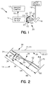
- Fig. 1 generally illustrates an imaging system 10 according to the preferred embodiment of the present invention.
- the imaging system 10 includes an imaging camera 12 and optical filter 14.
- the imaging system 10 tracks movement of a target 18 before and while a laser beam 16 is incident upon the target 18.
- the laser beam 16 may be one of several laser beam types such as a molecular or atomic laser beam.
- IR infrared
- a portion of the laser beam 16 is scattered to produce radiation 20 comprised of infrared (IR) laser light components 22 having wavelengths equaling the wavelengths of the IR light forming the laser beam 16.
- IR infrared
- a deuterium fluoride laser beam may comprise 10 or more wavelengths.
- the radiation 20 similarly may comprise multiple IR laser light components 22.
- the target generates infrared (IR) object light components 23, such as from thermal radiation or from the exhaust of a rocket.
- the optical filter 14 blocks or filters out the radiation 20 produced from the laser beam 16. By filtering out radiation 20, the optical filter 14 enables the imaging camera 12 to continue to track the target 18 along its trajectory by the IR object light components 23.
- the optical filter 14 includes a first diffraction grating 24 positioned to receive incident light 26.
- Incident light 26 is received in parallel and contains multiple wavelengths including the IR laser light components 22 and IR object light components 23.
- the diffraction grating 24 separates the incident light 26 into multiple discrete rays by bending light of different wavelengths by different angles.
- the diffraction grating 24 bends the light over a dispersion angle ⁇ associated with the spectral range of the filter 14.
- the dispersion angle ⁇ of the filter 14 corresponds to the angle 30 between the highest and lowest wavelengths 28 of the laser beam 16.
- the angle ⁇ may vary so long as the angular dispersion of the diffraction grating 24 sufficiently separates the wavelengths 28 to enable the filter 14 to operate.
- the wavelengths 28 are incident upon a lens 32 which is located a distance 34 from the diffraction grating 24.
- the distance 34 corresponds to the focal length of the lens 32 so that the diffraction grating 24 is located at the object plane of the lens 32. Accordingly, an image is focused by the lens 32 at a focal plane 38 on an opposite side of the lens 32 a distance 36 from the lens 32.
- the distance 36 may equal the focal length F of the lens 32.
- a concave mirror may be substituted for the lens 32. While the lens 32 may be presumed to produce negligible dispersion of the light rays incident thereon, such negligible dispersion may be further eliminated through the use of concave mirrors.
- Each wavelength 28 corresponds to, a separate spectral line.
- the lens 32 focuses each wavelength component 28 to a separate individual focal point at the focal plane 38 of the lens 32.
- a mask 54 extends along the focal plane 38. The mask 54 blocks the IR laser light components 22 and passes the object light components 23.
- a second lens 62 is provided downstream of the mask 54. The second lens 62 is located from the mask 54 a distance 64 corresponding to the focal length F of lens 62, in order to place the mask 54 at the object plane of the lens 62.
- a second diffraction grating 66 is located downstream of the lens 62 a distance 68 corresponding to the focal length F of the lens 62. The second diffraction grating 66 is located at the image plane of the second lens 62.
- Fig. 3 illustrates the cooperation between the diffraction grating 24 and lens 32 in more detail.
- two parallel incident rays 27 and 29 contain multiple wavelengths which are dispersed by the diffraction grating 24.
- the lowest and highest wavelengths 40 and 42 of the incident ray 27 may be dispersed at an angle ⁇ .
- the lowest and highest wavelengths 44 and 46 of incident ray 29 may be dispersed at a dispersion angle ⁇ .
- the lowest wavelengths 40 and 44 are focused by the lens 32 at a point 41 upon the focal plane 38 at a distance 36 from the lens 32.
- the highest wavelengths 42 and 46 are focused by the lens 32 at a point 43 at the focal plane 38.
- Diffraction grating 24 and lens 32 cooperate to focus each wavelength of the incident light 27 and 29 at different points upon the focal plane 38 based on the wavelength of the ray. While not illustrated, the diffraction grating 24 and lens 32 perform a similar focusing operation with respect to each wavelength of the IR laser light components 22 and the IR object light components 23.
- the laser beam 16 may include five wavelength components.
- the lens 36 focuses the laser wavelengths at five discrete points (only points 41 and 43 are shown).
- the mask 54 is divided into segments, each of which corresponds to a spectral line.
- the mask includes blocking regions 48-52 at the segments corresponding to the spectral lines of the IR laser light components 22.
- the mask includes apertures 56-59 at each of the segments (between the blocking regions) corresponding to the spectral lines of the IR object light components 23. Adjacent spectral lines of the IR laser light components 22 may be separated by several spectral lines of the IR object light components 23. Thus, apertures 56-59 may each span multiple segments. Wavelengths focused at apertures 56-59 are allowed to pass through the mask 54 as illustrated by light ray 60.
- the light ray 60 that passes through the mask 54 continues onward until contacting the second lens 62 (Fig. 2).
- the second lens 62 receives diverging incoming rays and focuses same upon the second diffraction grating 66 to produce multi-wavelength output light rays 70 having the wavelengths of the input light 26, except for the blocked IR laser light components 22.
- the second diffraction grating 66 collimates the multi-wavelength output rays 70 which are passed to the imaging camera 12 (Fig. 1) via an optical link 72.
- the diffraction grating 66 produces an unsheared parallel output beam.
- a multi-line input beam comprised of multiple parallel lines or rays 26 is incident upon the diffraction grating 24.
- the diffraction grating may have 450 dispersion lines per millimeter.
- the first order diffracted wavelengths 28 are transmitted through lens 32 (or a concave mirror) of focal length F to be emitted therefrom in parallel with one another.
- the wavelengths 40, 42, 44 and 46 (Fig. 3) of the laser beam 16 are focused at individual points 41 and 43 upon the mask 54.
- the wavelengths associated with the IR object light, such as ray 60 are focused at points corresponding to the apertures of the mask 54. Thus, all of the wavelengths of the laser beam 16 are blocked and the remaining wavelengths are transmitted therethrough to the second lens 62.
- the spectral lines of the laser beam 16 are well separated from one another as compared to the line width associated with a single wavelength. Stated another way, a substantial distance exists between adjacent blocking regions 48-52 in order to afford apertures 56-59 of sufficient width to pass a large percentage of the incident light having wavelengths other than the wavelengths of the laser beam 16.
- molecular and some atomic laser beams exhibit the above desired wavelength distribution. It is desirable to utilize a molecular or atomic laser beam, in which a large distribution exists between wavelengths in order to maximize the throughput of the mask 54. A high efficiency diffraction grating 24 is also required to maximize the throughput.
- the second grating 66 may be removed if the user is only interested in the spectral content of the filtered rays passed through the lens 62.
- a geometric optics ray matrix analysis of the optical system illustrates that the focal point of either of lenses 32 and 62 is displaced a distance F ⁇ from the optical axis (illustrated at 74 in Fig. 3) due to the diffraction grating dispersion.
- the beam transmitted at the exit plane of the second lens 62 has a spectral shear which may be removed by placing a diffraction grating 66 at a distance 68 from the lens 62, where the distance 68 corresponds to the imaging plane of the object plane at diffraction grating 24.
- the second diffraction grating 66 may produce an unsheared parallel output beam with all wavelengths overlapped and the laser spectral lines removed. According to the foregoing process, a target 18 may be viewed within the spectral range associated with the laser beam 16 while eliminating or greatly reducing noise produced by the laser beam 16.
- the laser beam may be a deuterium fluoride laser, hydrogen fluoride laser, and the like.
- the mask 54 be made by photolithography.
- the diffraction gratings 24 and 66 may include 450 spectral lines per millimeter.
- the focal length of lenses 32 and 62 may equal 20 cm.
- Homogeneous line widths may equal 0.05 cm -1 atm.
- two wavelengths of the deuterium fluoride laser may equal 3.6798 ⁇ m and 3.715 ⁇ m.
- the filter mask may have two blockage regions 0.15 mm wide with a 5 cm open region between the 3.6798 ⁇ m wavelengths assuming one atmosphere pressure. This example produces approximately 97% transmission of rays within the spectral range of the deuterium fluoride laser beam.
- atomic and molecular lasers may be utilized, such as CO, CO 2 lasers in the 5 and 10 ⁇ m spectral regions and the like.
Landscapes
- Engineering & Computer Science (AREA)
- Physics & Mathematics (AREA)
- General Physics & Mathematics (AREA)
- Computer Networks & Wireless Communication (AREA)
- Radar, Positioning & Navigation (AREA)
- Remote Sensing (AREA)
- Electromagnetism (AREA)
- Optics & Photonics (AREA)
- Aiming, Guidance, Guns With A Light Source, Armor, Camouflage, And Targets (AREA)
- Control Of Position, Course, Altitude, Or Attitude Of Moving Bodies (AREA)
- Optical Radar Systems And Details Thereof (AREA)
- Investigating Or Analysing Materials By Optical Means (AREA)
- Spectrometry And Color Measurement (AREA)
- Lenses (AREA)
Applications Claiming Priority (2)
| Application Number | Priority Date | Filing Date | Title |
|---|---|---|---|
| US90089797A | 1997-07-25 | 1997-07-25 | |
| US900897 | 1997-07-25 |
Publications (1)
| Publication Number | Publication Date |
|---|---|
| EP0893704A2 true EP0893704A2 (de) | 1999-01-27 |
Family
ID=25413267
Family Applications (1)
| Application Number | Title | Priority Date | Filing Date |
|---|---|---|---|
| EP98110506A Withdrawn EP0893704A2 (de) | 1997-07-25 | 1998-06-09 | Abbildungssystem mit optischem Filter für Streulaserstrahlung |
Country Status (4)
| Country | Link |
|---|---|
| EP (1) | EP0893704A2 (de) |
| JP (1) | JP2942552B2 (de) |
| KR (1) | KR19990013443A (de) |
| CA (1) | CA2240558A1 (de) |
Cited By (6)
| Publication number | Priority date | Publication date | Assignee | Title |
|---|---|---|---|---|
| US7391936B2 (en) | 2005-01-21 | 2008-06-24 | Lucent Technologies, Inc. | Microfluidic sensors and methods for making the same |
| US7435391B2 (en) | 2003-05-23 | 2008-10-14 | Lucent Technologies Inc. | Light-mediated micro-chemical reactors |
| US7780813B2 (en) | 2005-06-09 | 2010-08-24 | Alcatel-Lucent Usa Inc. | Electric field mediated chemical reactors |
| CN102221450A (zh) * | 2011-04-18 | 2011-10-19 | 中国工程物理研究院应用电子学研究所 | 一种激光系统跟瞄偏差测量装置 |
| CN104898126A (zh) * | 2015-05-19 | 2015-09-09 | 哈尔滨工业大学 | 一种基于微小卫星平台的合成孔径光学成像系统及方法 |
| RU2635901C1 (ru) * | 2016-07-12 | 2017-11-16 | Акционерное общество "Новосибирский приборостроительный завод" | Лазерный имитатор стрельбы |
Family Cites Families (3)
| Publication number | Priority date | Publication date | Assignee | Title |
|---|---|---|---|---|
| US5056914A (en) * | 1990-07-12 | 1991-10-15 | Ball Corporation | Charge integration range detector |
| JPH05126954A (ja) * | 1991-11-08 | 1993-05-25 | Mitsubishi Electric Corp | レ−ザ照射装置 |
| JP2857744B2 (ja) * | 1996-01-18 | 1999-02-17 | バブコック日立株式会社 | 飛行体位置計測装置 |
-
1998
- 1998-06-09 EP EP98110506A patent/EP0893704A2/de not_active Withdrawn
- 1998-06-12 CA CA002240558A patent/CA2240558A1/en not_active Abandoned
- 1998-06-23 KR KR1019980023753A patent/KR19990013443A/ko not_active Ceased
- 1998-07-27 JP JP10211025A patent/JP2942552B2/ja not_active Expired - Fee Related
Cited By (7)
| Publication number | Priority date | Publication date | Assignee | Title |
|---|---|---|---|---|
| US7435391B2 (en) | 2003-05-23 | 2008-10-14 | Lucent Technologies Inc. | Light-mediated micro-chemical reactors |
| US7391936B2 (en) | 2005-01-21 | 2008-06-24 | Lucent Technologies, Inc. | Microfluidic sensors and methods for making the same |
| US7780813B2 (en) | 2005-06-09 | 2010-08-24 | Alcatel-Lucent Usa Inc. | Electric field mediated chemical reactors |
| CN102221450A (zh) * | 2011-04-18 | 2011-10-19 | 中国工程物理研究院应用电子学研究所 | 一种激光系统跟瞄偏差测量装置 |
| CN102221450B (zh) * | 2011-04-18 | 2013-01-02 | 中国工程物理研究院应用电子学研究所 | 一种激光系统跟瞄偏差测量装置 |
| CN104898126A (zh) * | 2015-05-19 | 2015-09-09 | 哈尔滨工业大学 | 一种基于微小卫星平台的合成孔径光学成像系统及方法 |
| RU2635901C1 (ru) * | 2016-07-12 | 2017-11-16 | Акционерное общество "Новосибирский приборостроительный завод" | Лазерный имитатор стрельбы |
Also Published As
| Publication number | Publication date |
|---|---|
| JP2942552B2 (ja) | 1999-08-30 |
| CA2240558A1 (en) | 1999-01-25 |
| JPH11159999A (ja) | 1999-06-15 |
| KR19990013443A (ko) | 1999-02-25 |
Similar Documents
| Publication | Publication Date | Title |
|---|---|---|
| US8427633B1 (en) | Laser beam analysis apparatus | |
| FI90289C (fi) | Optinen komponentti | |
| EP0702817B1 (de) | Vorrichtung zur verbesserung der schärfentiefe eines strichmarkierungslesers | |
| EP2673620B1 (de) | Linienlichtquelle für raman- oder andere spektroskopiesysteme | |
| TWI571180B (zh) | 用於監視雷射束的裝置及方法 | |
| EP0867697B1 (de) | Lichtquelle und messmethode | |
| CN110657889B (zh) | 使用窄带光学滤波器的高分辨率单光电二极管光谱仪 | |
| AU764535B2 (en) | Method and device for analysing the three-dimensional distribution of a component in a sample | |
| US9366856B2 (en) | Apparatus and methods for combining and separating multiple beams | |
| EP0893704A2 (de) | Abbildungssystem mit optischem Filter für Streulaserstrahlung | |
| EP0315663B1 (de) | Sensor für ununterbrochene wellenfront mit gedrängtem aufbau | |
| US5298727A (en) | Device for reading bar codes on semiconductor surfaces | |
| EP0325158B1 (de) | Röntgenstrahlvorrichtung, ausgestattet mit einem Strahlungsbereich-Monitor | |
| CN113253472B (zh) | 一种用于光束合成系统的参考光产生装置及方法 | |
| US7839550B1 (en) | Volume holographic filter with broad acceptance angle and narrow spectral bandwidth | |
| US6728488B1 (en) | Optical systems employing anamorphic beams and diffraction gratings | |
| US6882775B1 (en) | Apparatus and method for multiplexing and de-multiplexing optical signals employing a anamorphic beams and diffraction gratings | |
| CN116438030A (zh) | 光加工装置 | |
| CN101223628A (zh) | 抑制雷射链路处理系统的工作雷射射束失真的方法 | |
| US5760959A (en) | Interferential position measuring device with three detectors | |
| JPH07244238A (ja) | 共焦点走査型顕微鏡 | |
| US6574253B2 (en) | Device for monitoring the emission wavelength of a laser | |
| EP0254731B1 (de) | Spektrometer mit steuerbarer frequenzdurchlässigkeit | |
| JPH0519680B2 (de) | ||
| JPWO2022168467A5 (de) |
Legal Events
| Date | Code | Title | Description |
|---|---|---|---|
| PUAI | Public reference made under article 153(3) epc to a published international application that has entered the european phase |
Free format text: ORIGINAL CODE: 0009012 |
|
| AK | Designated contracting states |
Kind code of ref document: A2 Designated state(s): AT BE CH CY DE DK ES FI FR GB GR IE IT LI LU MC NL PT SE |
|
| AX | Request for extension of the european patent |
Free format text: AL;LT;LV;MK;RO;SI |
|
| STAA | Information on the status of an ep patent application or granted ep patent |
Free format text: STATUS: THE APPLICATION HAS BEEN WITHDRAWN |
|
| 18W | Application withdrawn |
Withdrawal date: 19991011 |