EP0893708A2 - Guide d'ondes lumineuses avec diffusion avant - Google Patents
Guide d'ondes lumineuses avec diffusion avant Download PDFInfo
- Publication number
- EP0893708A2 EP0893708A2 EP98113819A EP98113819A EP0893708A2 EP 0893708 A2 EP0893708 A2 EP 0893708A2 EP 98113819 A EP98113819 A EP 98113819A EP 98113819 A EP98113819 A EP 98113819A EP 0893708 A2 EP0893708 A2 EP 0893708A2
- Authority
- EP
- European Patent Office
- Prior art keywords
- light
- light guide
- scattering particles
- carrier material
- introduction point
- Prior art date
- Legal status (The legal status is an assumption and is not a legal conclusion. Google has not performed a legal analysis and makes no representation as to the accuracy of the status listed.)
- Withdrawn
Links
- 239000002245 particle Substances 0.000 claims abstract description 41
- 239000012876 carrier material Substances 0.000 claims abstract description 30
- 239000000463 material Substances 0.000 claims abstract description 13
- 229920003229 poly(methyl methacrylate) Polymers 0.000 claims abstract description 10
- 239000004926 polymethyl methacrylate Substances 0.000 claims abstract description 10
- 239000004793 Polystyrene Substances 0.000 claims abstract description 5
- CQEYYJKEWSMYFG-UHFFFAOYSA-N butyl acrylate Chemical compound CCCCOC(=O)C=C CQEYYJKEWSMYFG-UHFFFAOYSA-N 0.000 claims abstract description 3
- QIWKUEJZZCOPFV-UHFFFAOYSA-N phenyl 2-methylprop-2-enoate Chemical compound CC(=C)C(=O)OC1=CC=CC=C1 QIWKUEJZZCOPFV-UHFFFAOYSA-N 0.000 claims abstract description 3
- 229920000139 polyethylene terephthalate Polymers 0.000 claims abstract 4
- 239000005020 polyethylene terephthalate Substances 0.000 claims abstract 4
- 229920001577 copolymer Polymers 0.000 claims abstract 2
- -1 polyethylene terephthalate Polymers 0.000 claims abstract 2
- 229920005644 polyethylene terephthalate glycol copolymer Polymers 0.000 claims abstract 2
- 238000010521 absorption reaction Methods 0.000 claims 7
- 239000011230 binding agent Substances 0.000 claims 1
- 230000002093 peripheral effect Effects 0.000 claims 1
- 238000012805 post-processing Methods 0.000 claims 1
- 239000004020 conductor Substances 0.000 abstract description 2
- 239000011162 core material Substances 0.000 description 3
- 238000009826 distribution Methods 0.000 description 3
- 238000001125 extrusion Methods 0.000 description 3
- 238000005286 illumination Methods 0.000 description 3
- 229920002223 polystyrene Polymers 0.000 description 3
- 238000011109 contamination Methods 0.000 description 2
- 230000001681 protective effect Effects 0.000 description 2
- 238000004026 adhesive bonding Methods 0.000 description 1
- 239000002390 adhesive tape Substances 0.000 description 1
- 230000032683 aging Effects 0.000 description 1
- 238000000149 argon plasma sintering Methods 0.000 description 1
- 230000005540 biological transmission Effects 0.000 description 1
- 230000015572 biosynthetic process Effects 0.000 description 1
- 238000003490 calendering Methods 0.000 description 1
- 239000000969 carrier Substances 0.000 description 1
- 230000001609 comparable effect Effects 0.000 description 1
- 238000010276 construction Methods 0.000 description 1
- 230000000694 effects Effects 0.000 description 1
- 238000005516 engineering process Methods 0.000 description 1
- 238000002594 fluoroscopy Methods 0.000 description 1
- 238000009499 grossing Methods 0.000 description 1
- 238000001746 injection moulding Methods 0.000 description 1
- 238000002372 labelling Methods 0.000 description 1
- 238000004519 manufacturing process Methods 0.000 description 1
- 238000000034 method Methods 0.000 description 1
- 239000013307 optical fiber Substances 0.000 description 1
- 238000007788 roughening Methods 0.000 description 1
- 238000006748 scratching Methods 0.000 description 1
- 230000002393 scratching effect Effects 0.000 description 1
- 239000000243 solution Substances 0.000 description 1
- 238000003892 spreading Methods 0.000 description 1
- 238000003466 welding Methods 0.000 description 1
Images

Classifications
-
- G—PHYSICS
- G02—OPTICS
- G02B—OPTICAL ELEMENTS, SYSTEMS OR APPARATUS
- G02B6/00—Light guides; Structural details of arrangements comprising light guides and other optical elements, e.g. couplings
- G02B6/0001—Light guides; Structural details of arrangements comprising light guides and other optical elements, e.g. couplings specially adapted for lighting devices or systems
- G02B6/0011—Light guides; Structural details of arrangements comprising light guides and other optical elements, e.g. couplings specially adapted for lighting devices or systems the light guides being planar or of plate-like form
- G02B6/0033—Means for improving the coupling-out of light from the light guide
- G02B6/0035—Means for improving the coupling-out of light from the light guide provided on the surface of the light guide or in the bulk of it
- G02B6/0036—2-D arrangement of prisms, protrusions, indentations or roughened surfaces
-
- G—PHYSICS
- G02—OPTICS
- G02B—OPTICAL ELEMENTS, SYSTEMS OR APPARATUS
- G02B6/00—Light guides; Structural details of arrangements comprising light guides and other optical elements, e.g. couplings
- G02B6/0001—Light guides; Structural details of arrangements comprising light guides and other optical elements, e.g. couplings specially adapted for lighting devices or systems
- G02B6/0011—Light guides; Structural details of arrangements comprising light guides and other optical elements, e.g. couplings specially adapted for lighting devices or systems the light guides being planar or of plate-like form
- G02B6/0033—Means for improving the coupling-out of light from the light guide
- G02B6/0035—Means for improving the coupling-out of light from the light guide provided on the surface of the light guide or in the bulk of it
- G02B6/004—Scattering dots or dot-like elements, e.g. microbeads, scattering particles, nanoparticles
- G02B6/0041—Scattering dots or dot-like elements, e.g. microbeads, scattering particles, nanoparticles provided in the bulk of the light guide
-
- G—PHYSICS
- G02—OPTICS
- G02B—OPTICAL ELEMENTS, SYSTEMS OR APPARATUS
- G02B6/00—Light guides; Structural details of arrangements comprising light guides and other optical elements, e.g. couplings
- G02B6/0001—Light guides; Structural details of arrangements comprising light guides and other optical elements, e.g. couplings specially adapted for lighting devices or systems
Definitions
- the invention relates to a light guide with forward scatter with the characteristics of the respective generic term of claim 1 and claim 5.
- a light guide is known from EP-A2-0 656 548.
- the known light guide of EP-A2-0 656 548 while avoiding the undesirable surface structuring poured into shapes in plate form.
- the light turns on at least initiated an edge of the plate, at least a flat side of the plate serves as a light exit surface.
- such light guides without any embedded Scattering particles were common in the light guide according to EP-A2-0 656 548 for the purpose of uniform Illumination of the light exit surface in the transparent Carrier material of the light guide also transparent scattering particles with some refractive index different from the carrier material stored, which, based on the carrier material, preferably 0.02 to 0.5% by weight, at most as the upper limit of the weight percentage of the scattering particles 1.0% by weight is indicated on the carrier material.
- the light guide according to the invention with forward scatter is also in a main use case (cf. claim 17) plate-shaped, also the light introduction point on at least one edge, usually a long one Edge, and the light exit surface on at least one Main surface of the plate are arranged.
- a main use case cf. claim 17
- the light introduction point on at least one edge usually a long one Edge
- the light exit surface on at least one Main surface of the plate are arranged.
- the light exit surface can Taper plate thickness from the point of light introduction, for what a wedge-shaped taper is known per se, but within the framework the invention also for the most constant possible illumination can perform another function, especially the reverse Proportionality to the distance from the light introduction point.
- the invention also extends in other applications to other light guide geometries (see also claim 18).
- the invention has for its object an alternative Specify the structure of the light guide, at least for certain applications, the light guide according to EP-A2-0 656 548 is superior.
- the invention means known per se combined in a new way. So there will be a color shift inside of the light guide depending on the distance to the light source due to the higher proportion by weight of the scattering particles on the carrier material consciously accepted. It has been shown that such a color shift due to adapted roughness of the Light exit surface completely sufficient for practical cases can be compensated. Such a roughness offers about it also the advantage that the light exit surface is less sensitive as a smooth surface against scratching or too Contamination from surface contamination with e.g. greasier Skin of a person. Has proven to be particularly effective the light guide according to the invention when its dimensions are relatively small.
- the invention almost opens it up new applications of uniform backlighting of information areas, such as timetables, Practice signs, name badges, house numbers, small ones Information and information signs, LCD displays and LCD screens. That does not exclude the inventive Light guides also in larger applications of street signs to use up to advertising space.
- a rough structure of the light exit surface is in different embodiments from the already mentioned DE-U1 94 01 126 known per se. Furthermore, e.g. from DE-A1-42 16 341 per se with translucent lighting fixtures, such as lamp covers and skylights, if necessary are formed by injection molding or extrusion, known, scattering particles in the carrier material of more than 1.0% by weight on the carrier material. This is different from the purpose of the invention, the incident at the light entry point Light to the opposite light exit surface spread as much as possible to the side, for example at Lamp covers to achieve that on the light exit surface the image of the lamp no longer appears. In this with the forward scatter light guides according to the invention scattering particles in the Backing material of more than 1.0% by weight, yes of far more than this limit, rather typical.
- Claims 2 and 3 relate to preferred proportions by weight the scattering particle in relation to the carrier material, which are clearly above the upper limit according to EP-A2-0 656 548.
- the inventive one Light guide the scattering particles a spherical Form that appears to be useful for forward scattering and at the same time in a controlled way light components distributed over the light exit surface.
- the carrier material as well as the scattering particles
- Materials and structures of the scattering particles used become.
- EP-A2-0 656 548 describes this as the carrier material already an acrylic glass, for claim 11 in the frame the invention indicates preferred possible substitutes.
- Material of the scattering particles polystyrene or butyl acrylate too use is, for example, from EP-A2-0 269 324, page 3, first full paragraph, known. Phenyl methacrylate the material of the scattering particles is specified in DE-A1-42 16 341.
- the material of the scattering particles from one the carrier material adjusted and cross-linked in each case Surrounding the shell is, for example, from EP-A2-0 269 324 in connection with EP-A1-0 342 283 known per se.
- EP-A2-0 269 324 in connection with EP-A1-0 342 283 known per se.
- This can be done in a preferred manner in case of use an acrylic glass as a carrier material insert, the spherical shell of interlinked acrylic glass is formed and each encloses a core made of polystyrene, the core being the actual spreading function of the Scattered particles take over.
- Claims 14 to 24 relate to the structure of the light guide according to the invention specially adapted or adaptable further training in application technology. So use claims 14 the rough structure of the invention Light exit surface in a further function as air-loaded Support surface for one supported on the rough structure illuminated diffuser layer.
- This diffuser layer can itself serve as an independent light surface, e.g. as a sign or direction sign, or one from another Illuminated component, e.g. Floor element, wall element or ceiling element, or an information carrier layer be, e.g. for timetables, practice signs, name badges or house numbers.
- LEDs are quasi monochromatic Light sources that are used in the forward scatter anyway not subject to change in color distribution.
- an original connection of a light emitting diode or a light-emitting diode arrangement with the light guide is obtained for itself a surface light as a ready-to-use, ready-to-connect Structures.
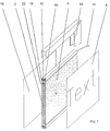
- the plate-shaped light guide 2 according to FIG. 1 is made from a carrier material, e.g. from a colorless Acrylic glass (PMMA).
- a carrier material e.g. from a colorless Acrylic glass (PMMA).
- PMMA colorless Acrylic glass
- spherical scattering particles in this acrylic glass 4 homogeneously stored in the embodiment shown at the light exit surface 6 somewhat more evenly stand out narrow area distribution and the illustrated Form the roughness of the light exit surface 6.
- the protruding scattering particles 4 on the light exit surface 6 also serve as air pressures Support surface for a layered illuminated diffuser layer, which is an information carrier layer 8 here.
- FIGS. 2a and 2b respectively extends the upper edge of the plate-shaped light guide plate 2 over its entire length - or deviating from the illustrations only over a shorter length - one LED light bar.
- a light-emitting diode arrangement is shown 12 on a common conductor strip (SMD LED - Surface Mounted Device-Light Emitting Diodes) with a power supply cable 14 is provided.
- the LED arrangement 12 is between a colorless, transparent Light exit window 16 and a highly reflective U-profile 18 arranged and as an independent LED light bar trained and protected against external influences.
- the Light exit window 16 is expedient on the edge of the plate-shaped light guide 2 directly by means of a transparent adhesive tape glued on or directly with this Welded edge. This edge serves as a light introduction point 22 in the light guide 2.
- FIGS. 2a and 2b show two further exemplary embodiments one for example (and preferably) by coextrusion produced two-layer plate-shaped layer structure of a light guide according to the invention.
- the one in the thicker colorless layer 31 at the light introduction point 30 Incoming part of the light can travel longer distances cover without distraction by refraction than in the thinner one forward scattering layer 32 or 33. Only after entering the thinner layer 32 or 33 and by the forward scatter Distraction caused by the light on at least one of the two flat sides of the plate-shaped light guide arranged light exit surface (s) emerge and information carrier or reflective rear wall (8 or 10 in Fig. 1) illuminate.
- the forward scattering Layer 33 can be used in addition to fluoroscopy translucent information carrier also essentially opaque reflective on the layer Illuminate 33 adjacent information carriers and through information without significant loss of sharpness through the layers 31 or recognize 32 or 33 through.
- the initially uniform thickness of the thicker colorless layer 31 so to decrease with increasing distance that through greater use of total reflection on the outside of layer 32 at a greater distance from the light introduction point 30 and after scattering at the Layer 33 has a uniform illuminance distribution the information carrier arranged behind or below the layer 33 results.
- the rough structure of the light exit surface can vary depending on the application on the outer flat side of layer 31 and / or the layer 32 or 33 may be provided, preferably at layer 32 or 33.
Landscapes
- Physics & Mathematics (AREA)
- General Physics & Mathematics (AREA)
- Optics & Photonics (AREA)
- Planar Illumination Modules (AREA)
- Illuminated Signs And Luminous Advertising (AREA)
Applications Claiming Priority (2)
| Application Number | Priority Date | Filing Date | Title |
|---|---|---|---|
| DE19731710 | 1997-07-23 | ||
| DE1997131710 DE19731710A1 (de) | 1997-07-23 | 1997-07-23 | Lichtleiter mit Vorwärtsstreuung |
Publications (2)
| Publication Number | Publication Date |
|---|---|
| EP0893708A2 true EP0893708A2 (fr) | 1999-01-27 |
| EP0893708A3 EP0893708A3 (fr) | 1999-12-01 |
Family
ID=7836682
Family Applications (1)
| Application Number | Title | Priority Date | Filing Date |
|---|---|---|---|
| EP98113819A Withdrawn EP0893708A3 (fr) | 1997-07-23 | 1998-07-23 | Guide d'ondes lumineuses avec diffusion avant |
Country Status (2)
| Country | Link |
|---|---|
| EP (1) | EP0893708A3 (fr) |
| DE (1) | DE19731710A1 (fr) |
Cited By (4)
| Publication number | Priority date | Publication date | Assignee | Title |
|---|---|---|---|---|
| EP1154199A1 (fr) * | 2000-05-12 | 2001-11-14 | Giorgio Ing. Gai | Panneau lumineux à lumière diffuse avec énergie de consommation basse et épaisseur limité |
| DE202009007565U1 (de) * | 2009-05-27 | 2010-10-14 | Hella Kgaa Hueck & Co. | Beleuchtete Anzeigetafel |
| DE102011000702A1 (de) * | 2011-02-14 | 2012-08-16 | Hella Kgaa Hueck & Co. | Rollfeldverkehrszeichen |
| EP1285198B2 (fr) † | 2000-05-19 | 2014-02-26 | Lucite International UK Limited | Dispositif d'éclairage par la tranche |
Families Citing this family (5)
| Publication number | Priority date | Publication date | Assignee | Title |
|---|---|---|---|---|
| DE29908755U1 (de) | 1999-05-18 | 1999-09-09 | Ströer Gesellschaft für innovative Außenwerbung mbH, 50999 Köln | Beleuchtete Anzeigevorrichtung |
| DE10224267A1 (de) * | 2002-05-31 | 2003-12-11 | Kostal Leopold Gmbh & Co Kg | Lichtleitkörper |
| DE102005017639B4 (de) * | 2005-04-15 | 2008-03-06 | Digitalicht Ag | Lichtleiteranordnung sowie Verfahren zur Herstellung einer solchen |
| US8517588B2 (en) | 2008-09-30 | 2013-08-27 | Rainier Horst | Integrally illuminated panel apparatus and methods |
| DE102011057097A1 (de) * | 2011-12-28 | 2013-07-04 | Richter Lighting Technologies Gmbh | Decken-Beleuchtungsanordnung |
Citations (1)
| Publication number | Priority date | Publication date | Assignee | Title |
|---|---|---|---|---|
| DE4216341A1 (de) * | 1992-05-16 | 1993-11-18 | Roehm Gmbh | Lichtstreuende Polymethacrylat-Formkörper mit hohen Temperatur- und Wetterechtheitswerten |
Family Cites Families (13)
| Publication number | Priority date | Publication date | Assignee | Title |
|---|---|---|---|---|
| JPS5938252A (ja) * | 1982-08-27 | 1984-03-02 | Mitsubishi Rayon Co Ltd | 光拡散性アクリル樹脂成形体 |
| CA1337104C (fr) * | 1986-11-18 | 1995-09-26 | William James Work | Polymeres thermoplastiques dispersant la lumiere |
| ES2046299T3 (es) * | 1988-05-18 | 1994-02-01 | Rohm And Haas Company | Composiciones polimericas termoestables y termoplasticas. |
| US5394255A (en) * | 1992-01-27 | 1995-02-28 | Sekisui Kagaku Kogyo Kabushiki Kaisha | Liquid crystal display using a plurality of light adjusting sheets angled at 5 degrees or more |
| JP3215218B2 (ja) * | 1993-04-05 | 2001-10-02 | 康博 小池 | 光散乱導光光源装置 |
| DE9316096U1 (de) * | 1993-10-21 | 1993-12-02 | Roehm Gmbh | Gleichmäßig ausgeleuchtete mehrschichtige Verbundsysteme |
| DE9318362U1 (de) * | 1993-12-01 | 1994-02-03 | Roehm Gmbh | Gleichmäßig ausgeleuchtete Lichtleiterplatten |
| US5659410A (en) * | 1993-12-28 | 1997-08-19 | Enplas Corporation | Surface light source device and liquid crystal display |
| JP3351889B2 (ja) * | 1993-12-28 | 2002-12-03 | 株式会社エンプラス | 映込防止機能を備えた面光源装置及び液晶表示装置 |
| DE9401126U1 (de) * | 1994-01-24 | 1994-03-17 | Roehm Gmbh | Beschriftete Lichtleiterelemente |
| DE4432515A1 (de) * | 1994-09-13 | 1996-03-14 | Willing Gmbh Dr Ing | Lichtleitkörper mit Lichtleitplatten aus Polymerisaten unterschiedlicher Brechzahl |
| JP3187280B2 (ja) * | 1995-05-23 | 2001-07-11 | シャープ株式会社 | 面照明装置 |
| DE29706201U1 (de) * | 1997-03-27 | 1997-05-28 | Osa Elektronik Gmbh | Leucht- oder Anzeigeelement mit einer Lichteinkopplung in einen Lichtleitkörper |
-
1997
- 1997-07-23 DE DE1997131710 patent/DE19731710A1/de not_active Ceased
-
1998
- 1998-07-23 EP EP98113819A patent/EP0893708A3/fr not_active Withdrawn
Patent Citations (1)
| Publication number | Priority date | Publication date | Assignee | Title |
|---|---|---|---|---|
| DE4216341A1 (de) * | 1992-05-16 | 1993-11-18 | Roehm Gmbh | Lichtstreuende Polymethacrylat-Formkörper mit hohen Temperatur- und Wetterechtheitswerten |
Cited By (6)
| Publication number | Priority date | Publication date | Assignee | Title |
|---|---|---|---|---|
| EP1154199A1 (fr) * | 2000-05-12 | 2001-11-14 | Giorgio Ing. Gai | Panneau lumineux à lumière diffuse avec énergie de consommation basse et épaisseur limité |
| US6530164B2 (en) | 2000-05-12 | 2003-03-11 | Giorgio Gai | Luminous diffused light panel with low energy consumption and limited thickness |
| AU775548B2 (en) * | 2000-05-12 | 2004-08-05 | Ing. Giorgio Gai | Luminous diffused light panel with low energy consumption and limited thickness |
| EP1285198B2 (fr) † | 2000-05-19 | 2014-02-26 | Lucite International UK Limited | Dispositif d'éclairage par la tranche |
| DE202009007565U1 (de) * | 2009-05-27 | 2010-10-14 | Hella Kgaa Hueck & Co. | Beleuchtete Anzeigetafel |
| DE102011000702A1 (de) * | 2011-02-14 | 2012-08-16 | Hella Kgaa Hueck & Co. | Rollfeldverkehrszeichen |
Also Published As
| Publication number | Publication date |
|---|---|
| DE19731710A1 (de) | 1999-02-18 |
| EP0893708A3 (fr) | 1999-12-01 |
Similar Documents
| Publication | Publication Date | Title |
|---|---|---|
| DE69724411T2 (de) | Beleuchtungsvorrichtung und anzeige welche diese verwendet | |
| EP2028048B1 (fr) | Corps de décoration doté d'éléments de décoration pouvant être éclairés | |
| EP2028046A1 (fr) | Corps de décoration | |
| EP0533301B1 (fr) | Signe indicatrice illuminée par derrière | |
| EP2561388A2 (fr) | Guide de lumière plan et luminaire | |
| DE202017107616U1 (de) | Linienförmige Lichtquelle | |
| WO2024088849A1 (fr) | Vitre de véhicule ayant une source de lumière et une couche conductrice de lumière | |
| DE20202435U1 (de) | Flachbauende Beleuchtungseinrichtung mit flächiger Lichtabstrahlung | |
| DE9300991U1 (de) | Licht-Leiteinrichtung, insbesondere für Werbezwecke | |
| EP0893708A2 (fr) | Guide d'ondes lumineuses avec diffusion avant | |
| EP2161497B1 (fr) | Unité d'éclairage | |
| DE29713114U1 (de) | Lichtleiter mit Vorwärtsstreuung | |
| DE102017129978A1 (de) | Linienförmige Lichtquelle | |
| DE102018004528B4 (de) | Fahrzeug-Beleuchtungsvorrichtung mit einem länglichen Lichtleiter und einer Abdeckung | |
| WO2024246124A1 (fr) | Dispositif d'affichage avec une caméra ir pour un véhicule | |
| WO2024094396A1 (fr) | Vitre de véhicule comprenant une source lumineuse et une couche conductrice de lumière | |
| EP0650155A1 (fr) | Système composite à plusieurs couches illuminé uniformement | |
| EP1010159B1 (fr) | Enseigne lumineuse, notamment lettre lumineuse | |
| WO2020058236A1 (fr) | Module d'éclairage, notamment destiné à être utilisé dans un dispositif d'éclairage pour véhicule automobile | |
| DE202007008950U1 (de) | Vorrichtung zur beleuchteten Präsentation | |
| DE102012004446A1 (de) | Lichtleitkörper mit effizienter Lichteinkopplung und Leuchtvorrichtung mit dem Lichtleitkörper | |
| DE202009014813U1 (de) | Fahrtreppe oder Fahrsteig | |
| EP0438768A1 (fr) | Dispositif d'affichage lumineux | |
| EP0985868A1 (fr) | Corps lumineux | |
| DE8625079U1 (de) | Beleuchtungskörper |
Legal Events
| Date | Code | Title | Description |
|---|---|---|---|
| PUAI | Public reference made under article 153(3) epc to a published international application that has entered the european phase |
Free format text: ORIGINAL CODE: 0009012 |
|
| AK | Designated contracting states |
Kind code of ref document: A2 Designated state(s): AT BE CH DE ES FR GB IT LI NL |
|
| AX | Request for extension of the european patent |
Free format text: AL;LT;LV;MK;RO;SI |
|
| PUAL | Search report despatched |
Free format text: ORIGINAL CODE: 0009013 |
|
| AK | Designated contracting states |
Kind code of ref document: A3 Designated state(s): AT BE CH CY DE DK ES FI FR GB GR IE IT LI LU MC NL PT SE |
|
| AX | Request for extension of the european patent |
Free format text: AL;LT;LV;MK;RO;SI |
|
| RIC1 | Information provided on ipc code assigned before grant |
Free format text: 6G 02B 5/02 A, 6G 02B 6/10 B, 6F 21V 8/00 B |
|
| 17P | Request for examination filed |
Effective date: 20000516 |
|
| AKX | Designation fees paid |
Free format text: AT BE CH DE ES FR GB IT LI NL |
|
| 17Q | First examination report despatched |
Effective date: 20000915 |
|
| STAA | Information on the status of an ep patent application or granted ep patent |
Free format text: STATUS: THE APPLICATION IS DEEMED TO BE WITHDRAWN |
|
| 18D | Application deemed to be withdrawn |
Effective date: 20010327 |