EP0893725B1 - Hochleistungs-Zoom-Objektiv - Google Patents
Hochleistungs-Zoom-Objektiv Download PDFInfo
- Publication number
- EP0893725B1 EP0893725B1 EP98113508A EP98113508A EP0893725B1 EP 0893725 B1 EP0893725 B1 EP 0893725B1 EP 98113508 A EP98113508 A EP 98113508A EP 98113508 A EP98113508 A EP 98113508A EP 0893725 B1 EP0893725 B1 EP 0893725B1
- Authority
- EP
- European Patent Office
- Prior art keywords
- zoom lens
- lens
- lens group
- high performance
- lens system
- Prior art date
- Legal status (The legal status is an assumption and is not a legal conclusion. Google has not performed a legal analysis and makes no representation as to the accuracy of the status listed.)
- Expired - Lifetime
Links
- 230000003287 optical effect Effects 0.000 claims abstract description 65
- 230000005855 radiation Effects 0.000 claims abstract 4
- 239000011521 glass Substances 0.000 claims description 8
- 230000003121 nonmonotonic effect Effects 0.000 claims description 3
- 230000029058 respiratory gaseous exchange Effects 0.000 description 7
- 238000000926 separation method Methods 0.000 description 4
- 238000010586 diagram Methods 0.000 description 3
- 230000009467 reduction Effects 0.000 description 3
- 230000001419 dependent effect Effects 0.000 description 2
- 230000000694 effects Effects 0.000 description 2
- 238000005259 measurement Methods 0.000 description 2
- 230000002250 progressing effect Effects 0.000 description 2
- 230000004075 alteration Effects 0.000 description 1
- 201000009310 astigmatism Diseases 0.000 description 1
- 230000015556 catabolic process Effects 0.000 description 1
- 230000008859 change Effects 0.000 description 1
- 238000010276 construction Methods 0.000 description 1
- 238000006731 degradation reaction Methods 0.000 description 1
- 238000005286 illumination Methods 0.000 description 1
- 238000004519 manufacturing process Methods 0.000 description 1
- 239000000463 material Substances 0.000 description 1
- 230000007246 mechanism Effects 0.000 description 1
- 239000005304 optical glass Substances 0.000 description 1
Images

Classifications
-
- G—PHYSICS
- G02—OPTICS
- G02B—OPTICAL ELEMENTS, SYSTEMS OR APPARATUS
- G02B15/00—Optical objectives with means for varying the magnification
- G02B15/14—Optical objectives with means for varying the magnification by axial movement of one or more lenses or groups of lenses relative to the image plane for continuously varying the equivalent focal length of the objective
- G02B15/143—Optical objectives with means for varying the magnification by axial movement of one or more lenses or groups of lenses relative to the image plane for continuously varying the equivalent focal length of the objective having three groups only
- G02B15/1435—Optical objectives with means for varying the magnification by axial movement of one or more lenses or groups of lenses relative to the image plane for continuously varying the equivalent focal length of the objective having three groups only the first group being negative
Definitions
- the invention relates to a high performance zoom lens system according to the precharacterizing part of claim 1.
- High performance optical systems such as for cinematography, high definition television (“HDTV”) and advanced television (“ATV”) require superior optical characteristics and performance which is normally accomplished by using separate objective lenses of different fixed focal lengths for achieving different photographic functions that are determined or influenced by the focal length.
- zoom lenses have one or more undesirable limitations such as the range of focal lengths, the inability to focus adequately over the entire focal length range, the inability to focus on close objects, the lack of adequate optical performance over the entire focal length range and focus distance, the cost, the large size and the like.
- a common form of zoom lens comprising a focusing lens group, a variator, a compensator and a relay arranged in this order.
- the focusing lens group is split into two subgroups. The first of said subgroups is movable while said second subgroup is stationary.
- a zoom lens system having 5 lens groups.
- the front lens group is split into 3 subgroups, namely a front positive, an intermediate positive, and a rear negative subgroup.
- the front positive and intermediate positive subgroups are movable with respect to the stationary rear subgroup.
- each lens element is identified by a numeral from 1 through 23 and the general configuration of each lens element is depicted, but the actual radius of each lens surface is set forth below in a table.
- the lens surfaces, including dummy optical surfaces used for design calculation purposes, are identified by the letter "S" followed by a numeral from S1 through S48.
- Each lens element has its opposite surfaces identified by a separate but consecutive surface number as, for example, lens element 1 has lens surfaces S2 and S3, lens element 11 has lens surfaces S21 and S22 and so forth, as shown in Fig. 1, except that for doublet lens components 1D, 2D, 3D and 4D the coincident facing lens surfaces are given a single surface number.
- doublet 1D is comprised of lens element 5 having a front lens surface S11 and a rear lens surface S12 and lens element 6 having a front lens surface S12 (coincidental) and a rear lens surface S13.
- the location of the object to be photographed, particularly as it relates to focus distance, is identified by a vertical line and the letter "O" on the optical axis
- dummy optical surfaces that are used in the optical data tables are identified by the vertical lines numbered S1, S10, S40 and S47
- the real image surface is identified by the numeral S48.
- Dummy surface S47 used for making the calculations substantially coincides with real image surface S48 at all positions of the focus and zoom lens groups.
- All of the lens surfaces are spherical except lens surfaces 3 and 44 which are aspheric surfaces that are non-spherical, non-plano but rotationally symmetrical about the optical axis.
- the focus lens group 51 comprises a first focus lens group 52 comprised of lens elements 1 and 2, and a second focus lens group 53 comprised of lens elements 3 and 4.
- a zoom lens group 54 comprises a first zoom lens group 55 that functions as a zoom compensator and a second lens group 56 that functions as a zoom variator.
- the zoom compensator 55 includes, from left to right in Fig.
- the zoom variator 56 includes, from left to right in Fig. 1, singlet lens element 11, an adjustable optical stop (iris) S23, singlet lens elements 12-15, a first doublet lens component 3D comprising lens elements 16 and 17, a second doublet lens component 4D comprising lens elements 18 and 19, and a singlet lens element 20.
- the auxiliary lens group 57 is comprised of singlet lens elements 21, 22 and 23.
- each lens element The positive or negative power of each lens element is set forth below in TABLE 1.
- the resultant optical power of each subgroup of lenses is as follows; the first focus group 52 is negative, the second focus group 53 is positive, the zoom compensator 55 is negative, the zoom variator 56 is positive, and the auxiliary lens group 57 is weakly positive.
- the combined optical power of the focus lens group 51 is negative.
- Each of the lens groups 52, 53, 55 and 56 are movable in both directions along the optical axis for focusing and zooming.
- the auxiliary lens group 57 remains stationary and at a fixed distance from the real image surface S48.
- the horizontal arrows with arrowheads on both ends in the upper portion of Fig. 1 indicate that each of the lens subgroups 52, 53, and 56 is movable in both axial directions but in a monotonic manner (i.e. in only one direction when progressing from one extreme to the other of adjustments) and the half-circle arrow and arrowheads for zoom lens subgroup 55 indicates that its movement is non-monotonic, that is, the movement reverses during zooming in one optical direction, such as from the minimum focal length to the maximum focal length.
- lens elements While only the lens elements are physically shown in Fig. 1, it is to be understood that conventional mechanical devices and mechanisms are provided for supporting the lens elements and for causing axial movement of the movable lens groups in a conventional lens housing or barrel.
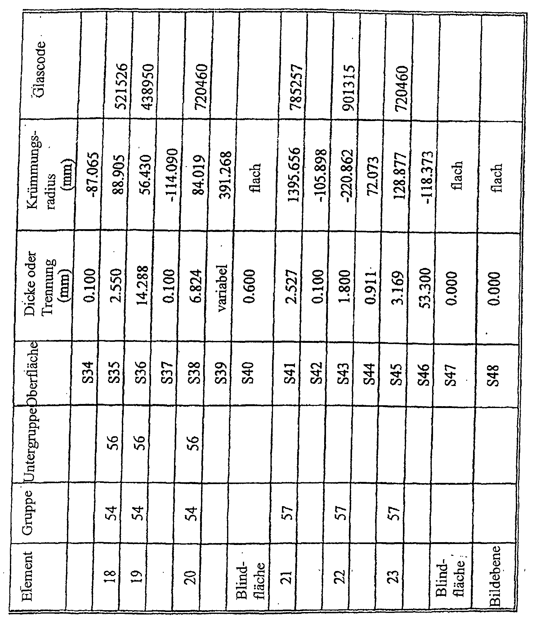
- TABLE 1 The lens construction and fabrication data for the above described zoom lens system 50 is set forth below in TABLE 1, which is extracted from data produced by CODE V® optical design software that is commercially available from Optical Research Associates, Inc., Pasadena, California, U.S.A., which was also used for producing the optical diagrams Figs. 1-5. All of the data in TABLE 1 is given at a temperature of 20°C (68°F) and standard atmospheric pressure (760mm Hg). Throughout this specification, including the Tables, all measurements are in millimeters (mm) with the exception of wavelengths which are in nanometers (nm). In TABLE 1, the first column "ITEM" identifies each optical element and each location, i.e.
- the second and third columns identify the "Group” and “Subgroup”, respectively, to which that optical element (lens) belongs with the same numerals used in Fig. 1.
- the fourth column “Surface” is a list of the surface numbers of the object (line “0" in Fig. 1 and "Object Plane” in TABLE 1), the dummy optical surfaces S1, S10, S40 and S47, the Iris (stop) S23 and each of the actual surfaces of the lenses, as identified in Fig. 1.
- the seventh column “Thickness or Separation” is the axial distance between that surface (fourth column) and the next surface, for example, the distance between surface S2 to surface S3 is 5.000mm.
- the eighth column is a list of the optical surface radius of curvature for each surface, with a minus sign (-) meaning the center of the radius of curvature is to the left of the surface, as viewed in Fig. 1, and "Flat” meaning either an optically flat surface or a dummy optical surface.
- the asterisk (*) for surfaces S3 and S44 indicate these are aspheric surfaces for which the "radius of curvature” is a base radius, and the formula and coefficients for those two surfaces are set forth as a footnote to TABLE 1 at the * (asterisk).
- the ninth column “Optical Power” sets forth whether the lens element ("Item” in the first column) is of a positive (Pos.) or negative (Neg.) optical power.
- TABLE 1 The next three columns of TABLE 1 relate to the "Material" between that surface (fourth column) and the next surface to the right in Fig. 1, with the tenth column “Type” indicating whether there is a lens (Glass) or empty space (Air) between those two surfaces. All of the lenses are glass and the eleventh column “Code” identifies the optical glass. For convenience, all of the lens glass has been selected from glass available from Ohara Corporation and the twelfth column "Name" lists the Ohara identification for each glass type, but it is to be understood that any equivalent or adequate glass may be used.
- Maximum Aperture Diameter provides the maximum diameter for each surface through which the light rays pass. All of the maximum aperture diameters, except for the Iris surface S23, are given at a wavelength of 546.1 nanometers for a maximum image height of 14.45mm and a constant f-number of f/2.2 at the Image Plane, for all Focus and Zoom Positions.
- the maximum aperture diameter of the Iris surface S23 is given in TABLE 1 at a wavelength of 546.1 nanometers and an f-number of f/2.2 at the Image Plane for Zoom Position Z4.
- the maximum aperture diameters at the Iris surface S23 at a wavelength of 546.1 nanometers and an f-number of f/2.2 at the Image Plane are 29.30mm, 33.35mm and 39.26mm, respectively.
- the Maximum Aperture Diameter is given as a paraxial value.
- the foregoing footnote * to TABLE 1 includes the equation for calculating the shape of the aspheric surfaces S3 and S44 for the value Z, wherein CURV is the curvature at the pole of the surface, Y is the height or distance from the optical axis of a specific point on the surface of the glass, K is the conic coefficient, and A, B, C, D, and E are the 4th, 6th, 8th, 10th and 12th, respectively, order deformation coefficients which are a well known equation and values for calculating the shape of an aspheric surface.
- the back focal length (BFL) which is the distance from the last optically refracting surface S46 to the real image surface S48 remains constant in all focus and zoom conditions that the lens system 50 can provide because the auxiliary lens group 57 is in a fixed position and the design of the lens system 50 is predicated on the facts that the real image surface S48 is in a fixed axial position and the image surface is flat.
- the zoom lens system 50 is provided with two aperture/field stops at the surfaces S11 and S44 which control the diameter of the aperture through which light rays may pass at each of those points to thereby cause any light rays in the zoom lens system radially beyond those diameters to be stopped.
- the four lens groups 52, 53, 55 and 56 are each axially movable independently and their respective movements are coordinated by any convenient means, such as conventional mechanical devices such as cams or the like, to accomplish the desired focusing and zooming functions.
- the focus lens groups 52 and 53 move independently of the zoom lens groups 55 and 56.
- the respective axial movements of the first and second focus lens groups 52 and 53 are coordinated.
- the zoom lens groups 55 and 56 always move at the same time and are coordinated, the zoom variator 56 moves in only one direction (monotonic) while progressing from the minimum focal length to the maximum focal length range but the zoom compensator moves in one direction and then the other direction (non-monotonic) in the minimum to maximum focal length range.
- the zoom lens groups 55 and 56 remain in the same respective positions throughout the full ranges of movement of the focus lens groups 52 and 53 (indicated by "All" in the Focus Position column of TABLE 1).
- Focus Position F1 the distance (Thickness or Separation column) to the next surface to the right in Fig. 1 from the Object Plane O is infinity (i.e.
- the Zoom Positions Z1, Z2, Z3 and Z4 are representative of four positions of the zoom lens groups 55 and 56 with Zoom Positions Z1 and Z4 being the extreme positions and Z2 and Z3 being intermediate positions for all focus lens group positions.
- the focal length of the lens system 50 varies for different focus distances and Zoom Positions and, for example, at infinity focus and for Zoom Position Z1 the focal length is 15.3mm, for Zoom Position Z2 the focal length is 23.9mm, for Zoom Position Z3 the focal length is 42.5mm, and for Zoom Position Z4 the focal length is 49.2m.
- the zoom range focal length may be reduced to about 20mm to 50mm with continuous focusing which range reduction removes the loss of field of view that would occur with the range of 14.5 to 50mm but normally the smaller focal length range will be acceptable because of the very large field of view produced by the lens system 50.
- the design of the zoom lens system 50 is for an image height of 14.45mm, which is the so-called Academy 35mm Cine film format that is rarely used at present and, therefore, the reduction in the smaller focal length range will not seriously affect the conventional 35mm Cine film format of about 12mm height.
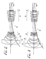
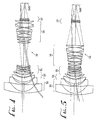
- Figs. 2-5 the zoom lens system 50 is shown with the focus lens groups and zoom lens groups in various positions and with light ray traces for those positions.
- Figs. 2 and 4 represent the focus position F1 and zoom position Z1 for which data is set forth above in TABLE 1 with infinity focus and a small focal length.
- Fig. 3 represents the focus position F3 and zoom position Z1 from TABLE 1 with a close focus and small focal length and is shown juxtaposed to Fig. 2 for comparing the relative positions of the focus and zoom lens groups 52, 53, 55 and 56, as well as the differences and similarities of the light ray traces.
- Fig. 2 the zoom lens groups 52, 53, 55 and 56, as well as the differences and similarities of the light ray traces.
- FIG. 5 represents the focus position F1 and zoom position Z4 from TABLE 1 with infinity focus and a large focal length and is shown juxtaposed to Fig. 4 for the same comparisons. Specifically, it should be noted from Figs. 2-5 that the pair of light ray traces closest to the axis from object space (at the left in the Figs.) converge to the optical axis at the image space.
- Fig. 1 represents the focus position F2 and zoom position Z2 from TABLE 1 with intermediate focus distance and focal length.
- the iris of a lens system is located behind (to the right in Figs. 1-5) of the last moving lens group but zoom lens system 50 has the iris S23 located within the second zoom lens group 56 and therefore the iris S23 moves axially therewith.
- the size of the aperture of iris S23 is adjusted as the zoom lens group 54 moves axially, as described above, with respect to the maximum aperture diameters listed in TABLE 1.
- the size of the aperture of iris S23 is not dependent on the positions of the first and second focus lens groups 52 and 53.
- the zoom lens system 50 maintains a constant f-number of about 2.2 in the image space through the zoom range and through the focus range.
- the optical performance data of zoom lens system 50 is set forth below in TABLE 2 wherein the diffraction based polychromatic modulation transfer function ("MTF") data is stated in percent (%) for five different Field Positions in seven different combinations of the zoom and focus positions set forth in TABLE 1, as representative examples, as well as the full field distortion data in percent (%) and the full field relative illumination data in percent (%) for those seven combination zoom and focus positions.
- the Field Positions are set forth in two values, both the actual image height (mm) from the optical axis and the normalized image height, which is the actual image height divided by the maximum image height.
- the MTF percentages are at the wavelengths and weightings set forth in the righthand column of TABLE 2, namely at 20 cycles/mm, which is a relatively standard measurement of optical performance, wherein the value "20 cycles/mm” means 20 pairs of black and white lines per millimeter on a chart from which the clarity is determined. All of the performance data is given at a temperature of 20°C (68°F), standard atmospheric pressure (760mm Hg), and at F/2.2 full aperture in image space.
- the zoom lens system 50 does provide substantially constant performance, as for example the MTF values, over a temperature range of 0° to 40°C (32° to 104°F) and, if a small degradation in performance (MTF) is acceptable, the operable temperature range can be extended to -10° to 50°C (14° to 122°F) or more.
- MTF percent modulation i.e. contrast
- values of 80% or more are considered exceptional and values between 50% and 80% are considered very good. From TABLE 2 it can be observed that almost every MTF percent exceeds 50%, except in full field where they all exceed 40%, and that most of the MTF values exceed 70%.
- TABLE 3 The values in TABLE 3 are as measured at a wavelength of 546.1 nanometers based on the difference between the full field principal ray angle (in degrees) at focus position F1 and focus positions F2 and F3, where the full field principal rays at all focus positions produce an image height of 14.45 mm at the image plane.
- the dimensions of this zoom lens system may be appropriately scaled up or down for use with various film image formats including, but not limited to, 16mm, Super 16mm, 35mm, 65mm, IMAX®, OMNIMAX® and the like, and various video formats including high definition television (HDTV), advanced television (ATV) and general digital television.
- film image formats including, but not limited to, 16mm, Super 16mm, 35mm, 65mm, IMAX®, OMNIMAX® and the like
- video formats including high definition television (HDTV), advanced television (ATV) and general digital television.
- the zoom lens system 50 of this invention is that of providing the wide range of focal lengths that are most commonly used in cine which eliminates the need for at least seven fixed focal length objective lenses for obtaining the proper versatility for high quality cinematography, whereby the use of this zoom lens system will result in greater flexibility and less cost.
- the unique design of the zoom lens system 50 creates a smaller lens than most high performance zoom lens systems of comparable range of focal lengths and only slightly larger than the largest fixed focal length objective lens in the same range.
- the unique lens design of the zoom lens system 50 virtually eliminates the so-called "breathing" problem wherein the image changes size when the focus is changed from short to long focus distances.
- Other features and advantages of the zoom lens system 50 will appear to those skilled in the art from the foregoing description and the accompanying drawings.
Landscapes
- Physics & Mathematics (AREA)
- General Physics & Mathematics (AREA)
- Optics & Photonics (AREA)
- Lenses (AREA)
- Non-Silver Salt Photosensitive Materials And Non-Silver Salt Photography (AREA)
- Compositions Of Macromolecular Compounds (AREA)
Claims (27)
- Hochleistungs-Zoom-Objektiv mit Mehrfach-Fokussierlinsengruppen (51), Mehrfach-Zoom-Linsengruppen (54) und einer Hilfslinsengruppe (57), die entlang einer gemeinsamen optischen Achse ausgerichtet und so angeordnet sind, dass sie von einem Objektraum ausgestrahlte Strahlung sammeln und die Strahlung als Realbild zu einem axial stationären Bildraum liefern, dadurch gekennzeichnet, dass die Linsengruppen in der folgenden Reihenfolge auf der optischen Achse und entlang dieser beweglich folgendermaßen angeordnet sind, wobei die Mehrfach-Fokussierlinsengruppen eine erste Fokussierlinsengruppe (52) von negativer optischer Leistung und eine zweite Fokussierlinsengruppe (53) von positiver optischer Leistung aufweisen, wobei die Mehrfach-Zoom-Linsengruppen eine erste Zoom-Linsengruppe mit einem Kompensator (55) von negativer optischer Leistung und eine zweite Zoom-Linsengruppe mit einem Variator (56) von positiver optischer Leistung aufweisen, wobei die erste und die zweite Fokussierlinsengruppe und die erste und die zweite Zoom-Linsengruppe sämtlich axial beweglich sind, und wobei die Hilfslinsengruppe axial stationär ist.
- Hochleistungs-Zoom-Objektiv nach Anspruch 1, wobei die erste und die zweite Fokussierlinsengruppe eine kombinierte negative optische Leistung aufweisen.
- Hochleistungs-Zoom-Objektiv nach Anspruch 1 oder 2, wobei die erste Zoom-Linsengruppe in nicht-gleichförmiger Weise zunächst in einer axialen Richtung und dann in der anderen axialen Richtung über einen vollständigen Bereich von Brennweiten zwischen einer minimalen Brennweite und einer maximalen Brennweite des Zoom-Objektivs axial beweglich ist.
- Hochleistungs-Zoom-Objektiv nach Anspruch 1, 2 oder 3, wobei die erste Fokussierlinsengruppe eine nicht-sphärische, nicht-plane, optisch brechende Oberfläche (S3) aufweist.
- Hochleistungs-Zoom-Objektiv nach Anspruch 1, 2, 3 oder 4, wobei die Hilfslinsengruppe eine nicht-sphärische, nicht-plane, optisch brechende Oberfläche aufweist (S44).
- Hochleistungs-Zoom-Objektiv nach Anspruch 5, wobei das Zoom-Objektiv verbleibende optisch brechende Oberflächen aufweist, die sämtlich im wesentlichen zumindest entweder sphärisch oder plan sind.
- Hochleistungs-Zoom-Objektiv nach Anspruch 1, 2, 3, 4 oder 5, wobei die Hilfslinsengruppe eine schwache optische Leistung aufweist und die einzige Hilfslinsengruppe darstellt.
- Hochleistungs-Zoom-Objektiv nach Anspruch 7, wobei die Hilfslinsengruppe eine positive optische Leistung aufweist.
- Hochleistungs-Zoom-Objektiv nach Anspruch 1 2, 3, 4, 5, 6, 7 oder 8, wobei die zweite Zoom-Linsengruppe eine einstellbare Irisblende (S23) aufweist.
- Hochleistungs-Zoom-Objektiv nach Anspruch 1, 2, 3, 4, 5, 6, 7, 8 oder 9, wobei in der ersten Zoom-Linsengruppe eine feste optische Blickfeldblende (S11) vorgesehen ist.
- Hochleistungs-Zoom-Objektiv nach Anspruch 1, 2, 3, 4, 5, 6, 7, 8, 9 oder 10, wobei in der Hilfslinsengruppe eine feste optische Blickfeldblende (S44) vorgesehen ist.
- Hochleistungs-Zoom-Objektiv nach einem der Ansprüche 1 bis 11, wobei die erste und die zweite Fokussierlinsengruppe Linsenelemente zum Minimieren von Größenänderungen von im Realbild erscheinenden Objekten während Änderungen der Brennweite von nahen zu entfernten Objekten mittels axialer Bewegung der ersten und zweiten Fokussierlinsengruppe aufweisen.
- Hochleistungs-Zoom-Objektiv nach einem der Ansprüche 1 bis 12, wobei die erste Fokussierlinsengruppe wenigstens zwei optisch brechende Linsenelemente (1, 2) umfasst und wenigstens eine asphärische Linsenoberfläche (S3) aufweist.
- Hochleistungs-Zoom-Objektiv nach einem der Ansprüche 1 bis 13, wobei die zweite Fokussierlinsengruppe wenigstens zwei optisch brechende Linsenelemente (3, 4) aufweist.
- Hochleistungs-Zoom-Objektiv nach einem der Ansprüche 1 bis 14, wobei die erste Zoom-Linsengruppe sechs optisch brechende Linsenelemente (5, 6, 7, 8, 9, 10) aufweist, welche zwei Paare von Doppelobjektiven (1D, 2D) aufweisen.
- Hochleistungs-Zoom-Objektiv nach einem der Ansprüche 1 bis 15, wobei die zweite Zoom-Linsengruppe zehn optisch brechende Linsenelemente (11-20) aufweist, welche zwei Paare von Doppelobjektiven (3D, 4D) aufweisen.
- Hochleistungs-Zoom-Objektiv nach einem der Ansprüche 1 bis 16, wobei die Hilfslinsengruppe wenigstens drei optisch brechende Linsenelemente (21, 22, 23) aufweist, und wenigstens eine asphärische Linsenoberfläche (S44) aufweist.
- Hochleistungs-Zoom-Objektiv nach Anspruch 1, 2 oder 3, wobei das Zoom-Linsensystem ein Linsenelement (1) aufweist, welches eine asphärische Linsenoberfläche (S3) aufweist, deren Profil durch folgende Gleichung und Koeffizienten bestimmt wird;
- CURV =
- 1/(Krümmungsradius)
- Y =
- Aperturhöhe, gemessen senkrecht zur optischen Achse
- K,A,B,C,D,E =
- Koeffizienten
- Z =
- Position eines Oberflächenprofils für einen gegebenen Y-Wert, gemessen entlang der optischen Achse von dem Pol (d.h. dem axialen Scheitelpunkt) der Oberfläche und
- Hochleistungs-Zoom-Objektiv nach Anspruch 18, wobei die asphärische Linsenoberfläche in der ersten Fokussierlinsengruppe enthalten ist.
- Hochleistungs-Zoom-Objektiv nach Anspruch 1, 2, 3, 18 oder 19, wobei das Zoom-Objektiv ein Linsenelement (22) mit einer asphärischen Linsenoberfläche (S44) aufweist, deren Profil durch die folgende Gleichung und Koeffizienten bestimmt wird;
- CURV =
- 1/(Krümmungsradius)
- Y =
- Aperturhöhe, gemessen senkrecht zur optischen Achse
- K,A,B,C,D,E =
- Koeffizienten
- Z =
- Position eines Oberflächenprofils für einen gegebenen Y-Wert, gemessen entlang der optischen Achse von dem Pol (d.h. dem axialen Scheitelpunkt) der Oberfläche und
- Hochleistungs-Zoom-Objektiv nach Anspruch 20, wobei die asphärische Linsenoberfläche in der Hilfslinsengruppe enthalten ist.
- Hochleistungs-Zoom-Objektiv nach einem der Ansprüche 1 bis 21, wobei die zweite Zoomlinsen-Gruppe in gleichförmiger Weise entlang des vollständigen Bereichs zwischen minimaler und maximaler Brennweite axial beweglich ist, und wobei die Hilfslinsengruppe axial stationär ist.
- Hochleistungs-Zoom-Objektiv nach Anspruch 1, wobei die erste Fokussierlinsengruppe wenigstens eine nicht-sphärische, nicht-plane, optisch brechende Oberfläche aufweist, wobei die zweite Zoom-Linsengruppe eine einstellbare optische Blende aufweist, wobei die Hilfslinsengruppe von positiver optischer Leistung mit wenigstens einer nicht-sphärischen, nichtplanen, optisch brechenden Oberfläche ist, wobei das Zoom-Objektiv verbleibende optisch brechende Oberflächen aufweist, die im wesentlichen zumindest entweder sphärisch oder plan sind, und wobei das Zoom-Objektiv mittels axialer Positionierung der Mehrfach-Fokussierlinsengruppen und der Mehrfach-Zoom-Linsengruppen im Realbild ein hohes Maß optischer Leistungsfähigkeit durch Fokussier- und Zoombereiche liefert.
- Hochleistungs-Zoomobjektiv nach Anspruch 1, mit einer Vielzahl von Glas-Linsenelementen (1-23), die auf der optischen Achse in solcher Reihenfolge ausgerichtet sind,
dass die Linsenelemente die Mehrfach-Fokussierlinsengruppen (51), welche die erste Fokussierlinsengruppe (52) und die zweite Fokussierlinsengruppe (53) aufweisen, bilden, wobei die Mehrfach-Zoom-Linsengruppen (54) die erste Zoom-Linsengruppe (55), die zweite Zoom-Linsengruppe (56) und die Hilfslinsengruppe (57) aufweisen;
wobei die erste Fokussierlinsengruppe Linsenelemente (1 und 2) aufweist, wobei die zweite Fokussierlinsengruppe Linsenelemente (3 und 4) aufweist, wobei die erste Zoom-Linsengruppe Linsenelemente (5 bis 10) aufweist, wobei die zweite Fokussierlinsengruppe Linsenelemente (11 bis 20) aufweist und wobei die Hilfslinsengruppe Linsenelemente (21, 22 und 23) aufweist; und
wobei die Linsenelementoberflächen, Blindflächen, eine Irisblende, eine Objektebene und eine Bildebene als (0) und (S1 bis S48) in der folgenden Tabelle bezeichnet sind, wobei die Linsenelementoberflächen S3 und S44 asphärisch sind, und wobei die Linsenelemente, Linsenelementoberflächen, Blindflächen, Irisblende, Objektebene und Bildebene die folgenden Beziehungen und Eigenschaften aufweisen:

- Hochleistungs-Zoom-Objektiv nach Anspruch 24, wobei die maximalen Aperturdurchmesser in mm bei jeder Oberfläche S1 bis S48 mit Ausnahme der Blindflächen, folgende Werte besitzen: 124.80 bei S2, 90.57 bei S3, 90.24 bei S4, 73.22 bei S5, 73.95 bei S6, 68.33 bei S7, 64.89 bei S8, 62.41 bei S9, 48.90 bei S11, 47.92 bei S12, 45.43 bei S13, 45.15 bei S14, 44.15 bei S15, 44.47 bei S16, 43.55 bei S17, 41.81 bei S18, 41.84 bei S19, 41.17 bei S20, 41.12 bei S21, 41.10 bei S22, 40.98 bei S23, 42.20 bei S24, 41.99 bei S25, 41.96 bei S26, 44.73 bei S27, 47.12 bei S28, 47.81 bei S29, 47.23 bei S30, 48.06 bei S31, 48.29 bei S32, 51.41 bei S33, 52.55 bei S34, 57.81 bei S35, 58.48 bei S36, 58.93 bei S37, 59.41 bei S38, 58.70 bei S39, 29.97 bei S41, 29.72 bei S42, 29.34 bei S43, 28.50 bei S44, 28.58 bei S45, 28.75 bei S46, 28.90 bei S48.
- Hochleistungs-Zoom-Objektiv nach Anspruch 24, wobei die asphärische Linsenoberfläche (S3) ein Profil besitzt, welches durch folgende Gleichung und Koeffizienten bestimmt wird:
- CURV =
- 1/(Krümmungsradius)
- Y
- = Aperturhöhe, gemessen senkrecht zur optischen Achse
- K,A,B,C,D,E =
- Koeffizienten
- Z =
- Position eines Oberflächenprofils für einen gegebenen Y-Wert, gemessen entlang der optischen Achse von dem Pol (d.h. dem axialen Scheitelpunkt) der Oberfläche und
- Hochleistungs-Zoom-Objektiv nach Anspruch 24 oder 26, wobei die asphärische Linsenoberfläche S44 ein Profil aufweist, welches durch folgende Gleichung und Koeffizienten bestimmt wird;
- CURV =
- 1/(Krümmungsradius)
- Y =
- Aperturhöhe, gemessen senkrecht zur optischen Achse
- K,A,B,C,D,E =
- Koeffizienten
- Z =
- Position eines Oberflächenprofils für einen gegebenen Y-Wert, gemessen entlang der optischen Achse von dem Pol (d.h. dem axialen Scheitelpunkt) der Oberfläche und
Applications Claiming Priority (4)
| Application Number | Priority Date | Filing Date | Title |
|---|---|---|---|
| US44521 | 1993-04-07 | ||
| US5374397P | 1997-07-25 | 1997-07-25 | |
| US53743P | 1997-07-25 | ||
| US09/044,521 US6122111A (en) | 1997-07-25 | 1998-03-19 | High performance zoom lens system |
Publications (2)
| Publication Number | Publication Date |
|---|---|
| EP0893725A1 EP0893725A1 (de) | 1999-01-27 |
| EP0893725B1 true EP0893725B1 (de) | 2002-09-18 |
Family
ID=26721663
Family Applications (1)
| Application Number | Title | Priority Date | Filing Date |
|---|---|---|---|
| EP98113508A Expired - Lifetime EP0893725B1 (de) | 1997-07-25 | 1998-07-20 | Hochleistungs-Zoom-Objektiv |
Country Status (8)
| Country | Link |
|---|---|
| US (1) | US6122111A (de) |
| EP (1) | EP0893725B1 (de) |
| JP (1) | JP4623769B2 (de) |
| AT (1) | ATE224551T1 (de) |
| AU (1) | AU731885B2 (de) |
| CA (1) | CA2243785C (de) |
| DE (1) | DE69808001T2 (de) |
| ES (1) | ES2182192T3 (de) |
Families Citing this family (14)
| Publication number | Priority date | Publication date | Assignee | Title |
|---|---|---|---|---|
| DE19952375A1 (de) * | 1999-10-30 | 2001-05-10 | Espera Werke Gmbh | Vorrichtung zum Anbringen von Haftetiketten auf Warenpackungen |
| US6829102B2 (en) * | 2002-03-20 | 2004-12-07 | Ricoh Company, Ltd. | Zoom lens, and camera and portable information terminal for utilizing zoom lens |
| DE10215434B4 (de) * | 2002-04-08 | 2015-01-15 | Carl Zeiss | Objektiv und Objektivserie |
| JP4354153B2 (ja) * | 2002-06-11 | 2009-10-28 | 株式会社リコー | ズームレンズ、カメラおよび携帯情報端末装置 |
| JP4720117B2 (ja) * | 2003-07-17 | 2011-07-13 | 株式会社ニコン | ズームレンズ |
| US7283309B2 (en) * | 2004-08-20 | 2007-10-16 | Panavision International, L.P. | Wide-range, wide-angle, rotatable compound zoom |
| US7123421B1 (en) * | 2005-04-22 | 2006-10-17 | Panavision International, L.P. | Compact high performance zoom lens system |
| GB0705910D0 (en) * | 2007-03-27 | 2007-05-09 | Dsam London Llp | Optical arrangement |
| JP5025386B2 (ja) * | 2007-08-24 | 2012-09-12 | キヤノン株式会社 | ズームレンズ |
| US8508864B2 (en) * | 2008-08-25 | 2013-08-13 | Acm Projektentwicklung Gmbh | Objective lens system |
| US7880978B2 (en) * | 2008-08-25 | 2011-02-01 | Acm Projektentwicklung Gmbh | Objective lens system |
| JP5637110B2 (ja) | 2011-09-21 | 2014-12-10 | コニカミノルタ株式会社 | インナーフォーカスズームレンズ |
| US9841538B2 (en) | 2013-04-04 | 2017-12-12 | Cooke Optics Ltd. | Anamorphic objective zoom lens |
| CN116338919B (zh) * | 2021-12-24 | 2025-07-29 | 东莞市宇瞳光学科技股份有限公司 | 一种变焦镜头 |
Family Cites Families (16)
| Publication number | Priority date | Publication date | Assignee | Title |
|---|---|---|---|---|
| US3705759A (en) * | 1970-05-20 | 1972-12-12 | Rank Organisation Ltd | Optical objective of variable focal length |
| JPS5114034A (de) * | 1974-07-24 | 1976-02-04 | Canon Kk | |
| JPS5232342A (en) * | 1975-09-08 | 1977-03-11 | Canon Inc | Variable magnification optical unit |
| JPS5614212A (en) * | 1979-07-13 | 1981-02-12 | Minolta Camera Co Ltd | Zoom lens system |
| JP2778232B2 (ja) * | 1990-09-07 | 1998-07-23 | キヤノン株式会社 | 広角ズームレンズ |
| US5264965A (en) * | 1991-02-15 | 1993-11-23 | Asahi Kogaku Kogyo Kabushiki Kaisha | Zoom lens |
| JP3074026B2 (ja) * | 1991-03-04 | 2000-08-07 | キヤノン株式会社 | 超広角型のズームレンズ |
| US5416639A (en) * | 1991-06-29 | 1995-05-16 | Olympus Optical Co., Ltd. | Zoom lens system |
| JP3260836B2 (ja) * | 1992-07-14 | 2002-02-25 | オリンパス光学工業株式会社 | 広角高変倍ズームレンズ |
| JP3057921B2 (ja) * | 1992-08-06 | 2000-07-04 | キヤノン株式会社 | ズームレンズ |
| JPH06242378A (ja) * | 1993-02-17 | 1994-09-02 | Canon Inc | ズームレンズ |
| JP3495772B2 (ja) * | 1993-11-30 | 2004-02-09 | キヤノン株式会社 | ズームレンズ及びそれを有するテレビカメラ |
| JP3414499B2 (ja) * | 1994-06-24 | 2003-06-09 | オリンパス光学工業株式会社 | ズームレンズ |
| JP3464719B2 (ja) * | 1994-10-18 | 2003-11-10 | 富士写真光機株式会社 | ズームレンズのフォーカシング方式 |
| JPH08201696A (ja) * | 1995-01-27 | 1996-08-09 | Canon Inc | ズームレンズ |
| US5638215A (en) * | 1995-06-20 | 1997-06-10 | Panavision International, L.P. | Objective lens system |
-
1998
- 1998-03-19 US US09/044,521 patent/US6122111A/en not_active Expired - Lifetime
- 1998-07-20 AT AT98113508T patent/ATE224551T1/de active
- 1998-07-20 DE DE69808001T patent/DE69808001T2/de not_active Expired - Lifetime
- 1998-07-20 EP EP98113508A patent/EP0893725B1/de not_active Expired - Lifetime
- 1998-07-20 ES ES98113508T patent/ES2182192T3/es not_active Expired - Lifetime
- 1998-07-23 CA CA002243785A patent/CA2243785C/en not_active Expired - Lifetime
- 1998-07-24 AU AU78425/98A patent/AU731885B2/en not_active Expired
- 1998-07-27 JP JP21085598A patent/JP4623769B2/ja not_active Expired - Lifetime
Also Published As
| Publication number | Publication date |
|---|---|
| ATE224551T1 (de) | 2002-10-15 |
| DE69808001T2 (de) | 2003-07-31 |
| CA2243785C (en) | 2007-03-20 |
| ES2182192T3 (es) | 2003-03-01 |
| AU731885B2 (en) | 2001-04-05 |
| CA2243785A1 (en) | 1999-01-25 |
| JP4623769B2 (ja) | 2011-02-02 |
| JPH1195100A (ja) | 1999-04-09 |
| DE69808001D1 (de) | 2002-10-24 |
| EP0893725A1 (de) | 1999-01-27 |
| AU7842598A (en) | 1999-02-04 |
| US6122111A (en) | 2000-09-19 |
Similar Documents
| Publication | Publication Date | Title |
|---|---|---|
| CA2608697C (en) | Compact high performance zoom lens system | |
| US4787718A (en) | Zoom lens system | |
| US5909318A (en) | Three-group zoom lens | |
| US20160116734A1 (en) | Optical system, image pickup apparatus, and optical device | |
| JP3035830B2 (ja) | ズームレンズ | |
| EP0566073A1 (de) | Zoomlinsenanordnung | |
| EP0893725B1 (de) | Hochleistungs-Zoom-Objektiv | |
| US7046454B2 (en) | Two-group zoom lens | |
| US6040949A (en) | Simple wide-angle zoom lens | |
| EP2321688B1 (de) | Objektivlinsensystem | |
| JP7781672B2 (ja) | 撮像レンズおよび撮像装置 | |
| JPH03288813A (ja) | ズームレンズ | |
| US10432870B2 (en) | Zoom lens and imaging apparatus | |
| JP7334137B2 (ja) | 撮像レンズおよび撮像装置 | |
| US6995923B2 (en) | Small lightweight zoom lens | |
| US5247324A (en) | Real image zoom viewfinder | |
| JP2025073886A (ja) | 変倍光学系および撮像装置 | |
| JP2025018369A (ja) | ズームレンズおよび撮像装置 | |
| JP7191884B2 (ja) | 撮像レンズおよび撮像装置 | |
| US5537254A (en) | Compact small format zoom lens | |
| JP7822865B2 (ja) | 撮像レンズおよび撮像装置 | |
| US6597514B2 (en) | Wide-angle zoom lens | |
| CN118348664B (zh) | 内窥镜适配镜头 | |
| JPH04264411A (ja) | アルバダ式ズームファインダ | |
| JPH05323193A (ja) | ズームレンズ |
Legal Events
| Date | Code | Title | Description |
|---|---|---|---|
| PUAI | Public reference made under article 153(3) epc to a published international application that has entered the european phase |
Free format text: ORIGINAL CODE: 0009012 |
|
| AK | Designated contracting states |
Kind code of ref document: A1 Designated state(s): AT CH DE ES FR GB IT LI |
|
| AX | Request for extension of the european patent |
Free format text: AL;LT;LV;MK;RO;SI |
|
| 17P | Request for examination filed |
Effective date: 19990726 |
|
| AKX | Designation fees paid |
Free format text: AT CH DE ES FR GB IT LI |
|
| 17Q | First examination report despatched |
Effective date: 20010309 |
|
| GRAG | Despatch of communication of intention to grant |
Free format text: ORIGINAL CODE: EPIDOS AGRA |
|
| GRAG | Despatch of communication of intention to grant |
Free format text: ORIGINAL CODE: EPIDOS AGRA |
|
| GRAH | Despatch of communication of intention to grant a patent |
Free format text: ORIGINAL CODE: EPIDOS IGRA |
|
| GRAH | Despatch of communication of intention to grant a patent |
Free format text: ORIGINAL CODE: EPIDOS IGRA |
|
| GRAA | (expected) grant |
Free format text: ORIGINAL CODE: 0009210 |
|
| AK | Designated contracting states |
Kind code of ref document: B1 Designated state(s): AT CH DE ES FR GB IT LI |
|
| REF | Corresponds to: |
Ref document number: 224551 Country of ref document: AT Date of ref document: 20021015 Kind code of ref document: T |
|
| REG | Reference to a national code |
Ref country code: GB Ref legal event code: FG4D |
|
| REG | Reference to a national code |
Ref country code: CH Ref legal event code: NV Representative=s name: PATMED AG Ref country code: CH Ref legal event code: EP |
|
| REF | Corresponds to: |
Ref document number: 69808001 Country of ref document: DE Date of ref document: 20021024 |
|
| REG | Reference to a national code |
Ref country code: ES Ref legal event code: FG2A Ref document number: 2182192 Country of ref document: ES Kind code of ref document: T3 |
|
| ET | Fr: translation filed | ||
| PLBE | No opposition filed within time limit |
Free format text: ORIGINAL CODE: 0009261 |
|
| STAA | Information on the status of an ep patent application or granted ep patent |
Free format text: STATUS: NO OPPOSITION FILED WITHIN TIME LIMIT |
|
| 26N | No opposition filed |
Effective date: 20030619 |
|
| PGFP | Annual fee paid to national office [announced via postgrant information from national office to epo] |
Ref country code: CH Payment date: 20110712 Year of fee payment: 14 |
|
| PGFP | Annual fee paid to national office [announced via postgrant information from national office to epo] |
Ref country code: ES Payment date: 20120824 Year of fee payment: 15 Ref country code: IT Payment date: 20120717 Year of fee payment: 15 |
|
| PGFP | Annual fee paid to national office [announced via postgrant information from national office to epo] |
Ref country code: AT Payment date: 20120626 Year of fee payment: 15 |
|
| REG | Reference to a national code |
Ref country code: CH Ref legal event code: PL |
|
| REG | Reference to a national code |
Ref country code: AT Ref legal event code: MM01 Ref document number: 224551 Country of ref document: AT Kind code of ref document: T Effective date: 20130720 |
|
| PG25 | Lapsed in a contracting state [announced via postgrant information from national office to epo] |
Ref country code: CH Free format text: LAPSE BECAUSE OF NON-PAYMENT OF DUE FEES Effective date: 20130731 Ref country code: LI Free format text: LAPSE BECAUSE OF NON-PAYMENT OF DUE FEES Effective date: 20130731 |
|
| PG25 | Lapsed in a contracting state [announced via postgrant information from national office to epo] |
Ref country code: IT Free format text: LAPSE BECAUSE OF NON-PAYMENT OF DUE FEES Effective date: 20130720 Ref country code: AT Free format text: LAPSE BECAUSE OF NON-PAYMENT OF DUE FEES Effective date: 20130720 |
|
| PG25 | Lapsed in a contracting state [announced via postgrant information from national office to epo] |
Ref country code: ES Free format text: LAPSE BECAUSE OF NON-PAYMENT OF DUE FEES Effective date: 20130721 |
|
| REG | Reference to a national code |
Ref country code: FR Ref legal event code: PLFP Year of fee payment: 19 |
|
| REG | Reference to a national code |
Ref country code: FR Ref legal event code: PLFP Year of fee payment: 20 |
|
| PGFP | Annual fee paid to national office [announced via postgrant information from national office to epo] |
Ref country code: FR Payment date: 20170613 Year of fee payment: 20 |
|
| PGFP | Annual fee paid to national office [announced via postgrant information from national office to epo] |
Ref country code: GB Payment date: 20170719 Year of fee payment: 20 Ref country code: DE Payment date: 20170711 Year of fee payment: 20 |
|
| REG | Reference to a national code |
Ref country code: DE Ref legal event code: R071 Ref document number: 69808001 Country of ref document: DE |
|
| REG | Reference to a national code |
Ref country code: GB Ref legal event code: PE20 Expiry date: 20180719 |
|
| PG25 | Lapsed in a contracting state [announced via postgrant information from national office to epo] |
Ref country code: GB Free format text: LAPSE BECAUSE OF EXPIRATION OF PROTECTION Effective date: 20180719 |