EP0893743A1 - Unité de développement avec ventilation pour la régulation d'une pression interne - Google Patents
Unité de développement avec ventilation pour la régulation d'une pression interne Download PDFInfo
- Publication number
- EP0893743A1 EP0893743A1 EP98305958A EP98305958A EP0893743A1 EP 0893743 A1 EP0893743 A1 EP 0893743A1 EP 98305958 A EP98305958 A EP 98305958A EP 98305958 A EP98305958 A EP 98305958A EP 0893743 A1 EP0893743 A1 EP 0893743A1
- Authority
- EP
- European Patent Office
- Prior art keywords
- toner
- developing unit
- developing
- roller
- housing
- Prior art date
- Legal status (The legal status is an assumption and is not a legal conclusion. Google has not performed a legal analysis and makes no representation as to the accuracy of the status listed.)
- Withdrawn
Links
Images

Classifications
-
- G—PHYSICS
- G03—PHOTOGRAPHY; CINEMATOGRAPHY; ANALOGOUS TECHNIQUES USING WAVES OTHER THAN OPTICAL WAVES; ELECTROGRAPHY; HOLOGRAPHY
- G03G—ELECTROGRAPHY; ELECTROPHOTOGRAPHY; MAGNETOGRAPHY
- G03G15/00—Apparatus for electrographic processes using a charge pattern
- G03G15/06—Apparatus for electrographic processes using a charge pattern for developing
- G03G15/08—Apparatus for electrographic processes using a charge pattern for developing using a solid developer, e.g. powder developer
- G03G15/0896—Arrangements or disposition of the complete developer unit or parts thereof not provided for by groups G03G15/08 - G03G15/0894
- G03G15/0898—Arrangements or disposition of the complete developer unit or parts thereof not provided for by groups G03G15/08 - G03G15/0894 for preventing toner scattering during operation, e.g. seals
-
- G—PHYSICS
- G03—PHOTOGRAPHY; CINEMATOGRAPHY; ANALOGOUS TECHNIQUES USING WAVES OTHER THAN OPTICAL WAVES; ELECTROGRAPHY; HOLOGRAPHY
- G03G—ELECTROGRAPHY; ELECTROPHOTOGRAPHY; MAGNETOGRAPHY
- G03G2215/00—Apparatus for electrophotographic processes
- G03G2215/01—Apparatus for electrophotographic processes for producing multicoloured copies
- G03G2215/0167—Apparatus for electrophotographic processes for producing multicoloured copies single electrographic recording member
- G03G2215/0174—Apparatus for electrophotographic processes for producing multicoloured copies single electrographic recording member plural rotations of recording member to produce multicoloured copy
- G03G2215/0177—Rotating set of developing units
Definitions
- the present invention relates to a developing unit and, more particularly to a developing unit having an air vent for controlling internal pressure capable of preventing toner from leaking to the outside of the developing unit. This is achieved by controlling the internal pressure of the developing unit which pressure increases as the volume of the contents inside of the developing unit is made to expand by the agitation of the toner received in the inside of the developing unit.
- an electrostatic latent image is formed by radiating light such as a laser beam generated by a laser scanning unit in a dotted image on the surface of a photosensitive body which reacts sensibly to the light. Afterwards, the electrophotographic image forming device forms a visible image on the surface of the photosensitive body by developing toner which is charged with an electrostatic force at the electrostatic latent image, and the toner developed on the photosensitive body is transferred onto and adhered to a recordable medium, and thereafter the printed image is outputted.
- light such as a laser beam generated by a laser scanning unit in a dotted image on the surface of a photosensitive body which reacts sensibly to the light.
- the electrophotographic image forming device forms a visible image on the surface of the photosensitive body by developing toner which is charged with an electrostatic force at the electrostatic latent image, and the toner developed on the photosensitive body is transferred onto and adhered to a recordable medium, and thereafter the printed image is outputted.
- the image forming device may include: an optical system which converts print data transmitted from a computer, fax, multifunctional machine or a copier connected to the image forming device into a code peculiar to a laser printer, and transmits the laser beam according to this code; a photosensitive body for forming the electrostatic latent image on the surface which is already charged by the transmitted laser beam; a developing unit for supplying the toner for forming the visible image to the electrostatic latent image of the photosensitive body; a transfer unit for transferring the real image formed on the photosensitive body to the recordable medium and adhering the real image onto the recordable medium; and a fixing unit for heat-fixing the toner on the recordable medium by applying heat to the toner which is adhered to the recordable medium.
- a separating wall for separating the inner part of the housing into two is located.
- An opening having a predetermined size is formed at the separating wall.
- one is a toner receiving region for receiving a bulk amount of toner and the other is a developing region for developing the toner supplied through the opening of the separating wall from the toner receiving region, at the electrostatic latent image of the photosensitive body.
- an agitator for rotating the toner by a certain rpm is located in order to move the toner to the developing region and to prevent the toner from agglomerating into lumps.
- a toner supply roller having a sponge roller shape is formed to contain the toner supplied through the opening of the separating wall.
- a developing roller is provided at a position where frictional force occurs through contact of the developing roller with the toner supply roller.
- a thin layer forming roller is arranged to closely contact the developing roller and is arranged in the developing region in order to ensure that the toner adhered temporarily to the developing roller is evenly applied and has the same thickness.
- the developing roller on which the toner is caused to be evenly adhered by the thin layer forming roller is located near to the photosensitive body. Accordingly, the toner adhered to the developing roller in the form of a thin layer is transferred to the photosensitive body on which the electrostatic latent image is formed by electrostatic attraction, and the electrostatic latent image of the photosensitive body is developed into the visible image.
- the toner for developing the real image on the electrostatic latent image of the photosensitive body has a size of 5 - 16 ⁇ m. Assuming that a certain amount of toner is contained in a space which is airtight and is agitated, the volume of the toner is caused to expand to about two times larger than the original volume due to its good mobility. The expansion of volume is caused by the air which enters pores between the particles of the toner.
- the expanded toner is contained in the toner receiving region and the developing region in the housing of the developing unit. Due to the expansion pressure of the toner generated when the toner is caused to expand, a high internal pressure is generated in the inside of the developing unit relative to the outside of the developing unit.
- a certain difference of the air pressure between the inner part and outer part of the developing unit is generated by the aforesaid internal pressure. Owing to the difference of the air pressure, particles of the toner each having a minute grain size of 5 - 16pm are caused to leak through minute pores of the developing unit, little by little.
- the toner can leak onto or into in a connecting part which has a clearance error when connecting the axis of one roller out of a plurality of rollers supported on the housing of the developing unit with an axis hole of the housing, in a gap between the developing roller and the housing, or in the pore of the housing which occurs when assembling the same.
- the leakage is prevented by locating a leakage prevention ring or a sponge at a part of the developing unit where leakage frequently occurs.
- a leakage prevention ring or a sponge due to the friction generated between the leakage prevention ring or a sponge and the component part of the developing unit, an overload or malfunction can be generated when operating the developing unit.
- an air vent for controlling the internal pressure for exhausting the internal air inside of the developing unit is located at a predetermined position of the developing unit for preventing leakage of the toner caused when the internal pressure generated due to the expansion of the toner received in the inside of the developing unit for forming an electrostatic latent image formed on a photosensitive drum, i.e., a photosensitive body is larger than the external pressure of the developing unit.
- developing unit comprising:
- said ventilation means is equipped with a vent hole which communicates between the inner and outer parts of said developing unit housing; and a filter which prevents passage of said toner through said vent hole.
- said filter is made of paper.
- said filter is a sponge.
- said filter comprises air transmitting pathways having a size larger than air particles and small than particles of toner.
- said thin layer forming means is a thin layer forming roller, and excess toner adhered to said thin layer forming roller is removed by a scraper.
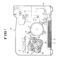
- FIG. 1 a color image forming device equipped with a developing unit according to the prevention is explained.
- a paper cassette 1 for stacking a plurality of printable media 2 for recording an image is located.
- a feed unit 3 is provided in order for the printable medium 2 of the paper cassette 1 to be supplied one by one (sheet by sheet) to a next process.
- the printable medium 2 supplied from the feed unit 3 is transported to a certain position, it is transported to a transfer roller 4 which is charged with a certain polarity. Afterwards, the printable medium 2 is retained on the transfer roller 4 by electrostatic force.
- a photosensitive drum 6 which is the photosensitive body is located close to the transfer roller 4. Adjacent the photosensitive drum 6, a charging roller for charging the photosensitive drum 6 with a certain polarity is located.
- an optical system 5 such as a laser scanning unit, is arranged for generating a laser beam and radiating the laser beam onto the photosensitive drum 6.
- the laser beam generated by the optical system 5 is radiated onto the photosensitive drum 6 charged with a certain polarity.
- the electrostatic latent image which is the same as the print data is formed at the part of the photosensitive drum 6 onto which the laser beam is radiated.
- the part of the photosensitive drum 6 where the electrostatic latent image is formed is developed by the toner supplied by a developing unit 7.
- the toner is received in a cyan developer 7a, a magenta developer 7b, a yellow developer 7c and a black developer 7d.
- the four developers 7a to 7d are fixed to and supported by a turret.
- the toner After developing the latent image by the toner at the photosensitive drum 6 by the developing unit 7 equipped with the four developers 7a to 7d the toner is scattered and transferred to the printable medium 2 from the photosensitive drum 6 by the difference of the electrostatic attraction with respect to the transfer roller 4.
- the toner transferred onto the printable medium 2 passes through the fixing rollers having a temperature of 167° - 200°C and then is fused onto the printable medium.
- a reference numeral 10 is a paper stacker (which is not illustrated) on which a plurality of printable media are outputted and stacked.
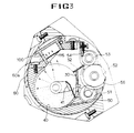
- the developing unit having the air vent for controlling the internal pressure according to the color image forming device having the above structure is explained with reference to FIG. 2.
- the housing of the developing unit has a certain cylindrical airtight region and is divided into two by a separating wall 30 which includes an opening with a certain area.
- one is a toner receiving region 40 in which a bulk amount of toner is stored.
- an agitator 41 is located for agitating the toner in order to supply the toner to the other region.
- the other region is a developing region 50 in which the toner supplied from the toner receiving region 40 is developed at the electrostatic latent image of the photosensitive drum 6.
- the charging amount of toner per unit of mass is optically set by frictionally rubbing the toner, and a toner supply roller 51, a developing roller 52, a thin layer forming roller 53 and a scraper 54 are arranged so that the charged toner can be supplied to the electrostatic latent image of the photosensitive drum.
- the toner supply roller 51 which has the form of a sponge roller is provided so that the toner supplied to the developing region 50 through the opening of the separating wall 30 by the agitator 41 from the toner receiving region 40 can be supplied initially.
- the developing roller 52 is arranged to contact to the toner supply roller 51 for subsequently supplying the toner to the photosensitive drum 6.
- the toner supply roller 51 is caused to rub against the developing roller 52 and the toner is frictionally charged with a certain voltage and thereby adhered to the developing roller 52 temporarily.
- the toner which is temporarily adhered to the developing roller 53 has a very uneven thickness, in the case that the toner is moved in this state directly to the photosensitive drum 6, the developing density becomes uneven and the print quality is degraded. Accordingly, in order to form a thin layer of toner adhered to the developing roller 52 which has an even thickness, the thin layer forming roller 53 is provided closely adjacent the developing roller 52.
- scraper or doctor blade 54 is located at the thin layer forming roller 53.
- the internal pressure in the toner receiving region 40 and the developing region 50 (which are the inner regions of the housing 60) becomes higher than the pressure of the outside of the housing 60.
- an air vent 100 for controlling the internal pressure is provided in the developing unit.
- the air vent 100 for controlling the internal pressure of the developing unit can be located in the toner receiving region 40 or the developing region 50.
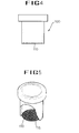
- FIGs. 4 and 5 there is shown an air vent for controlling the internal pressure of the developing unit.
- At least one air vent 100 is provided.
- At least one through hole 60a is formed in the housing 60 of the developing unit, by means of which the inner part and outer part of the housing 60 communicates with the outer part of the housing 60.
- the air vent 100 for controlling the internal pressure is equipped with the filter 110 which has a shape of pipe.
- the air vent 100 and filter 110 allow air to be exhausted from the inside of the developing unit while preventing toner from leaking to the outside.
- the air vent is located in hole 60a.
- a filter paper is used. It is also possible to use a sponge having minute vent holes.
- a suitable filter paper is one manufactured by Schleider & Schuell.
- the vent hole 115 has construction comprising meshes through which the toner having relatively larger particles cannot pass and the air having relatively smaller particles can pass.
- the transporting path of the toner in the developing unit equipped with the air vent 100 for controlling the internal pressure according to the present invention is illustrated.
- the dotted lines indicate paths for the toner and air which are mixed, and the solid lines are paths for the toner only.
- the toner received in the toner receiving region 40 is agitated by the rotation of the agitator 41, and thereby its volume becomes twice the original volume.
- One part of the toner which is doubled in volume is transported to the developing region 50 through the opening formed at the separating wall 30, and it becomes adhered to the electrostatic latent image of the photosensitive drum, thereby being developed.
- the other part of the toner is agitated by the agitator 41 and mixed with air, and it is not supplied to the developing region 50.
- the toner which is mixed with the air is transported towards the air vent 100 which controls the internal pressure due to the internal pressure of the developing region 50.
- the filter paper having the vent hole 115 for passing the air particles is attached to the entrance of the air vent 100 for controlling the internal pressure, the toner does not escape and only the air particles escape, thereby forming a low pressure region. Accordingly, the toner mixed with the air is transported towards the air vent 100.
- the toner mixed with the air is made to flow into the air vent 100 for controlling the internal pressure from the agitator 41, i.e., center part of the developing unit by the difference of the air pressure.
- the air vent 100 Out of the toner and air which flow into the air vent 100, only the air is exhausted to the outside of the developing unit, and thereby the internal pressure of the developing unit decreases.
- the difference between the pressure inside of the housing 60 of the developing unit and the pressure outside of the housing 60 also decreases.
Landscapes
- Physics & Mathematics (AREA)
- General Physics & Mathematics (AREA)
- Dry Development In Electrophotography (AREA)
Applications Claiming Priority (2)
| Application Number | Priority Date | Filing Date | Title |
|---|---|---|---|
| KR1019970034856A KR19990011671A (ko) | 1997-07-25 | 1997-07-25 | 내부압력 조정용 배기구를 갖는 현상장치 |
| KR9734856 | 1997-07-25 |
Publications (1)
| Publication Number | Publication Date |
|---|---|
| EP0893743A1 true EP0893743A1 (fr) | 1999-01-27 |
Family
ID=19515569
Family Applications (1)
| Application Number | Title | Priority Date | Filing Date |
|---|---|---|---|
| EP98305958A Withdrawn EP0893743A1 (fr) | 1997-07-25 | 1998-07-27 | Unité de développement avec ventilation pour la régulation d'une pression interne |
Country Status (3)
| Country | Link |
|---|---|
| EP (1) | EP0893743A1 (fr) |
| KR (1) | KR19990011671A (fr) |
| CN (1) | CN1103459C (fr) |
Cited By (1)
| Publication number | Priority date | Publication date | Assignee | Title |
|---|---|---|---|---|
| US7190920B2 (en) | 2002-03-18 | 2007-03-13 | Seiko Epson Corporation | Developing cartridge, air communication unit of developing cartridge and toner cartridge |
Families Citing this family (4)
| Publication number | Priority date | Publication date | Assignee | Title |
|---|---|---|---|---|
| KR100520510B1 (ko) * | 2003-11-22 | 2005-10-11 | 삼성전자주식회사 | 전자사진방식 화상형성장치의 현상장치 |
| JP4907504B2 (ja) * | 2007-11-26 | 2012-03-28 | 株式会社リコー | 画像形成装置 |
| CN102236294A (zh) * | 2010-04-21 | 2011-11-09 | 株式会社东芝 | 显影装置、图像形成装置及显影装置的减压方法 |
| KR20190006726A (ko) * | 2017-07-11 | 2019-01-21 | 에이치피프린팅코리아 유한회사 | 현상기 및 이를 채용한 전자사진방식 화상형성장치 |
Citations (7)
| Publication number | Priority date | Publication date | Assignee | Title |
|---|---|---|---|---|
| US4377334A (en) * | 1980-01-11 | 1983-03-22 | Olympus Optical Company Ltd. | Magnet roll developing unit |
| US4583112A (en) * | 1984-10-29 | 1986-04-15 | Xerox Corporation | Venting system for the developer housing of an electrostatic copying machine |
| US4963930A (en) * | 1988-08-29 | 1990-10-16 | Ricoh Company, Ltd. | Developing apparatus capable of preventing leakage of a developer |
| EP0578190A2 (fr) * | 1992-07-08 | 1994-01-12 | Konica Corporation | Dispositif de développement utilisé dans un appareil de formation d'images |
| US5592266A (en) * | 1994-09-08 | 1997-01-07 | Samsung Electronics Co., Ltd. | Electrophotographic process cartridge |
| JPH09230686A (ja) * | 1996-02-23 | 1997-09-05 | Ricoh Co Ltd | 画像形成装置 |
| EP0807865A2 (fr) * | 1996-05-17 | 1997-11-19 | Canon Kabushiki Kaisha | Dispositif de développement |
-
1997
- 1997-07-25 KR KR1019970034856A patent/KR19990011671A/ko not_active Withdrawn
-
1998
- 1998-07-17 CN CN98116086A patent/CN1103459C/zh not_active Expired - Fee Related
- 1998-07-27 EP EP98305958A patent/EP0893743A1/fr not_active Withdrawn
Patent Citations (7)
| Publication number | Priority date | Publication date | Assignee | Title |
|---|---|---|---|---|
| US4377334A (en) * | 1980-01-11 | 1983-03-22 | Olympus Optical Company Ltd. | Magnet roll developing unit |
| US4583112A (en) * | 1984-10-29 | 1986-04-15 | Xerox Corporation | Venting system for the developer housing of an electrostatic copying machine |
| US4963930A (en) * | 1988-08-29 | 1990-10-16 | Ricoh Company, Ltd. | Developing apparatus capable of preventing leakage of a developer |
| EP0578190A2 (fr) * | 1992-07-08 | 1994-01-12 | Konica Corporation | Dispositif de développement utilisé dans un appareil de formation d'images |
| US5592266A (en) * | 1994-09-08 | 1997-01-07 | Samsung Electronics Co., Ltd. | Electrophotographic process cartridge |
| JPH09230686A (ja) * | 1996-02-23 | 1997-09-05 | Ricoh Co Ltd | 画像形成装置 |
| EP0807865A2 (fr) * | 1996-05-17 | 1997-11-19 | Canon Kabushiki Kaisha | Dispositif de développement |
Non-Patent Citations (1)
| Title |
|---|
| PATENT ABSTRACTS OF JAPAN vol. 098, no. 001 30 January 1998 (1998-01-30) * |
Cited By (2)
| Publication number | Priority date | Publication date | Assignee | Title |
|---|---|---|---|---|
| US7190920B2 (en) | 2002-03-18 | 2007-03-13 | Seiko Epson Corporation | Developing cartridge, air communication unit of developing cartridge and toner cartridge |
| EP1486832A4 (fr) * | 2002-03-18 | 2010-01-06 | Seiko Epson Corp | Cartouche de developpement, dispositif de debit d'air pour cartouche de developpement, et cartouche de toner |
Also Published As
| Publication number | Publication date |
|---|---|
| CN1206857A (zh) | 1999-02-03 |
| KR19990011671A (ko) | 1999-02-18 |
| CN1103459C (zh) | 2003-03-19 |
Similar Documents
| Publication | Publication Date | Title |
|---|---|---|
| US7962084B2 (en) | Fixing device and image forming apparatus | |
| CN102053529B (zh) | 显影装置、显影盒、处理盒以及成像装置 | |
| US9098012B2 (en) | Electrophotographic image forming apparatus and process cartridge | |
| US7184693B2 (en) | Toner cartridge used with electrophotographic image forming apparatus | |
| JP4616591B2 (ja) | 画像形成装置 | |
| US6873819B2 (en) | Wasted toner storing apparatus of an image forming apparatus having a rotating dispersing member | |
| JP2006251132A (ja) | クリーニング装置及びこれを搭載した画像形成装置 | |
| EP0893743A1 (fr) | Unité de développement avec ventilation pour la régulation d'une pression interne | |
| US5091748A (en) | Toner supplying mechanism | |
| US6810221B1 (en) | Apparatus and method for discharging an electrophotography component | |
| CN100444039C (zh) | 显影盒及具有其的电子照相成像设备 | |
| US7349646B2 (en) | Toner cartridge used with an electrophotographic image forming apparatus | |
| KR100611988B1 (ko) | 현상장치 및 이를 적용한 화상형성장치 | |
| US6754465B2 (en) | Liquid image forming apparatus having squeeze unit | |
| JP2003208004A (ja) | トナーカートリッジおよびその梱包方法 | |
| KR100509507B1 (ko) | 전자사진방식 화상형성장치의 토너 카트리지 | |
| JP2020118712A (ja) | 画像形成装置、現像制御方法および現像制御プログラム | |
| JP2011107649A (ja) | 画像形成装置 | |
| US20060120750A1 (en) | Image forming apparatus | |
| JP2025164479A (ja) | 現像剤収容体、画像形成ユニットおよび画像形成装置 | |
| JP2005043899A (ja) | カラー電子写真方式の印刷機及びその作動方法 | |
| JP2000056560A (ja) | 現像装置及び電子写真画像形成装置 | |
| US20180231917A1 (en) | Developing unit, process cartridge, and image forming apparatus including process cartridge | |
| JP2009031700A (ja) | 画像形成装置 | |
| JP2008009228A (ja) | 粉体収容容器 |
Legal Events
| Date | Code | Title | Description |
|---|---|---|---|
| PUAI | Public reference made under article 153(3) epc to a published international application that has entered the european phase |
Free format text: ORIGINAL CODE: 0009012 |
|
| 17P | Request for examination filed |
Effective date: 19980817 |
|
| AK | Designated contracting states |
Kind code of ref document: A1 Designated state(s): DE FR GB |
|
| AX | Request for extension of the european patent |
Free format text: AL;LT;LV;MK;RO;SI |
|
| AKX | Designation fees paid |
Free format text: DE FR GB |
|
| 17Q | First examination report despatched |
Effective date: 20020513 |
|
| STAA | Information on the status of an ep patent application or granted ep patent |
Free format text: STATUS: THE APPLICATION IS DEEMED TO BE WITHDRAWN |
|
| 18D | Application deemed to be withdrawn |
Effective date: 20021126 |